Removal Procedure
- Remove the engine assembly with transaxle. Refer to Engine Replacement.
- Install the engine stand.
- Remove the intake manifold. Refer to Intake Manifold Removal.
- Remove the fuel tube assembly.
- Remove the fuel delivery pipe assembly.
- Remove the fuel injector assembly.
- Remove the ignition coil assembly.
- Remove the oil level dipstick sub-assembly. Refer to Oil Level Indicator Tube Replacement.
- Remove the exhaust manifold. Refer to Exhaust Manifold Removal.
- Remove the ventilation hose.
- Remove the water by-pass hoses.
- Remove the water by-pass pipe.
- Remove the inlet water hose.
- Remove the inlet water.
- Remove the thermostat.
- Remove the radio setting condenser.
- Remove the cylinder head cover assembly. Refer to Camshaft Cover Removal.
- Set the No. 1 cylinder to TDC/compression.
- Remove the crankshaft pulley.
- Remove the chain tensioner assembly. Refer to Timing Chain Tensioner Removal.
- Remove the timing chain cover assembly. Refer to Timing Chain Housing Removal
- Remove the timing chain cover oil seal.
- Remove the chain tensioner slipper.
- Remove the timing gear chain vibration damper.
- Remove the chain assembly.
- Remove the oil pump chain vibration damper.
- Inspect the camshaft timing gear assembly.
- Check the lock of the camshaft timing gear.
- After cleaning and degreasing the VVT oil hole on the intake side of the camshaft bearing cap, completely seal the oil hole with adhesive tape (3) or equivalent as shown in the illustration to prevent air from leaking.
- Prick a hole (2) in the tape covering the oil hole as shown.
- Apply approximately 150 kPa (22 psi) of air pressure to the hole to release the lock pin.
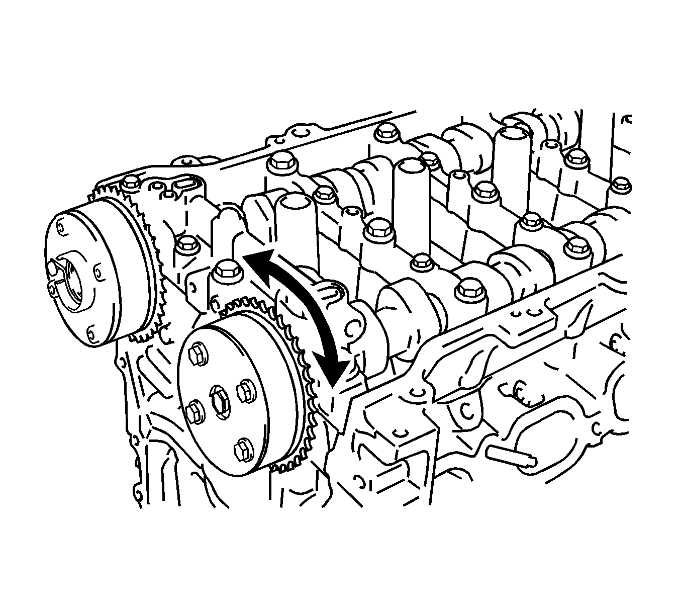
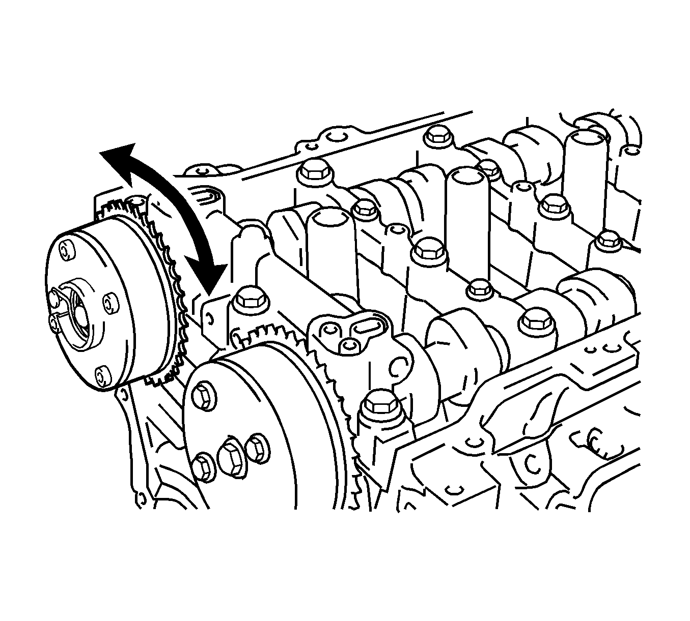
- Forcibly turn the camshaft timing gear assembly in the advanced direction (counterclockwise).
- Turn the camshaft timing gear assembly within its movable range (26.5-28.5 degrees) 2 or 3 times without turning it to the most retarded position. Make sure that the camshaft timing gear assembly turns smoothly.
- Remove the adhesive tape from the camshaft bearing cap.
- Inspect the camshaft timing exhaust gear assembly.
- Check the lock of the camshaft timing exhaust gear.
- After cleaning and degreasing the VVT oil hole on the exhaust side of the camshaft bearing cap, completely seal the oil hole with adhesive tape (3) or equivalent as shown in the illustration to prevent air from leaking.
- Prick a hole (2) in the tape covering the oil hole as shown.
- Apply approximately 200 kPa (28 psi) of air pressure to the hole to release the lock pin.
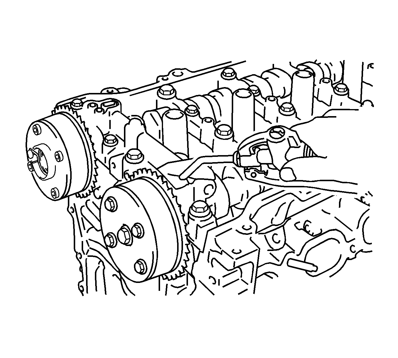
- Using a screwdriver with its tip wrapped with tape, forcibly turn the camshaft timing exhaust gear in the retard direction (clockwise).
- Using a screwdriver with its tip wrapped with tape, turn the camshaft timing exhaust gear within its movable range (19 to 21 degrees) 2 or 3 times without turning it to the most advanced position. Make sure that the camshaft timing exhaust gear turns smoothly.
- Remove the adhesive tape from the camshaft bearing cap.
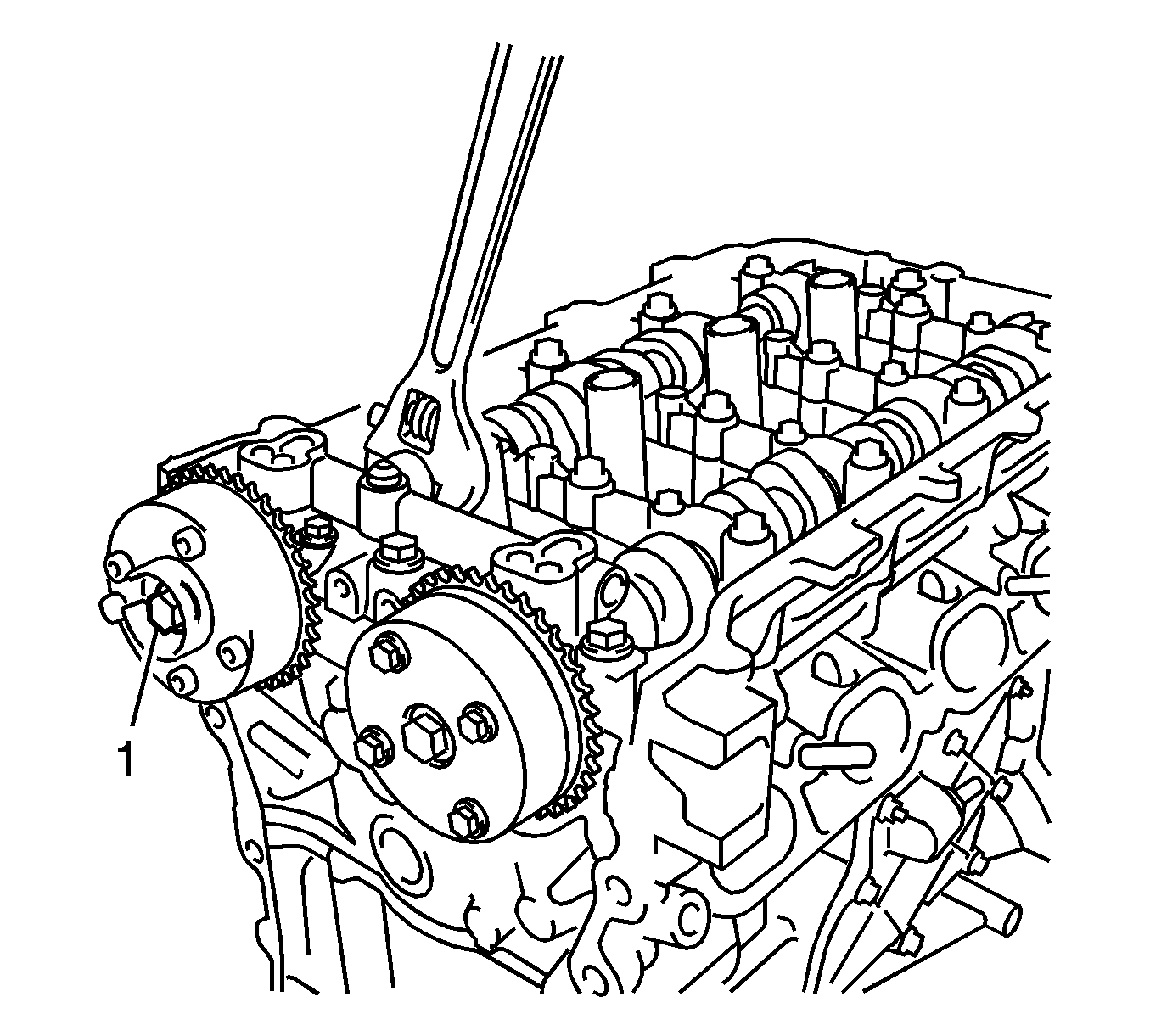
- Remove the flange bolt (1) while holding the hexagonal portion of the camshaft, and then remove the camshaft timing gear assembly.
- Remove the flange bolt (1) while holding the hexagonal portion of the camshaft, and then remove the camshaft timing exhaust gear assembly.
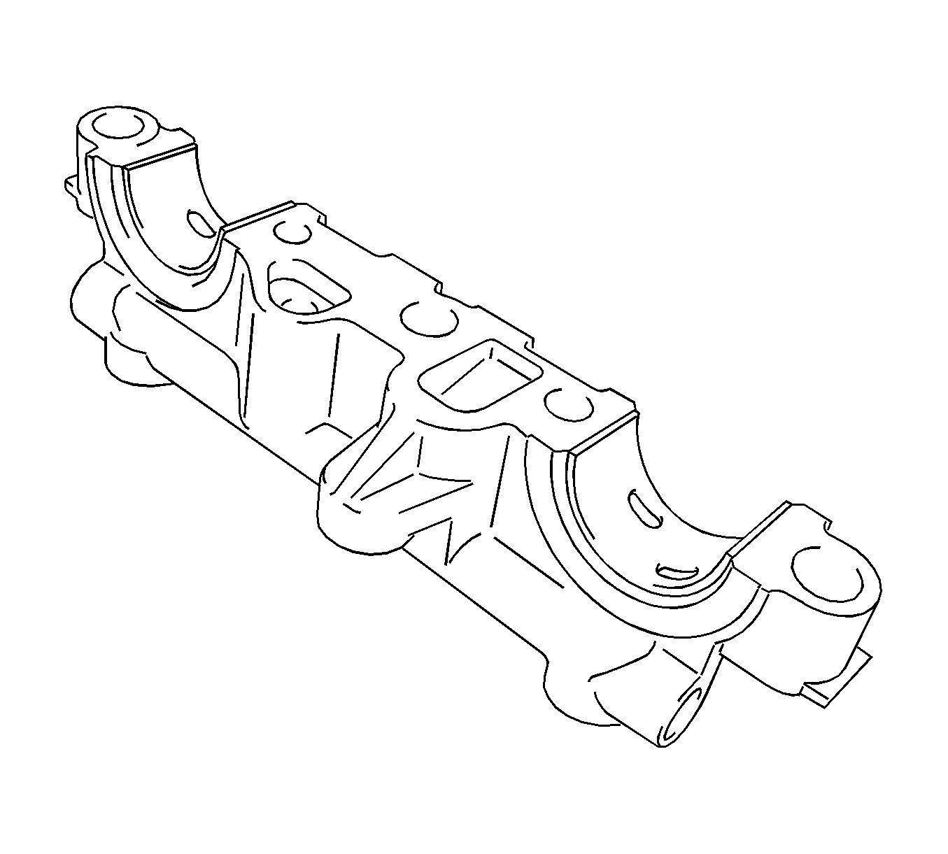
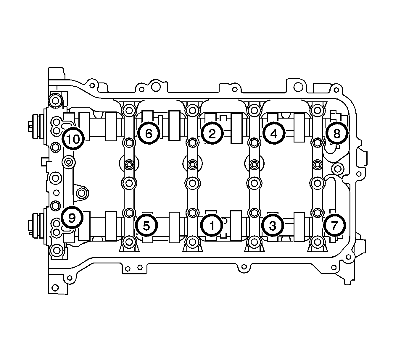
- Remove camshaft bearing cap--Uniformly loosen and remove the 10 bearing cap bolts in the sequence shown in the illustration.
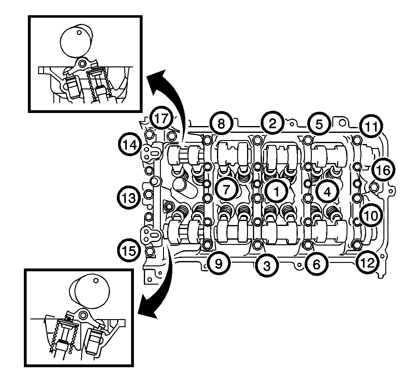
- Uniformly loosen and remove the 15 bearing cap bolts in the sequence shown in the illustration.
- Remove the 5 bearing caps.
- Remove the intake camshaft.
- Remove the exhaust camshaft.
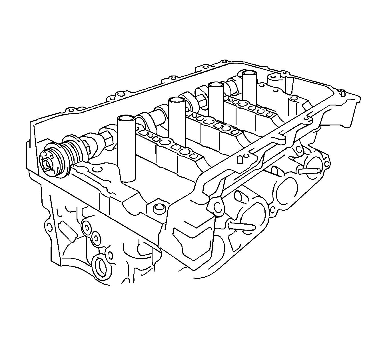
- Remove the valve rocker arm subassembly.
- Remove the valve lash adjuster assembly.
- Remove the 2 camshaft bearings from the cap.
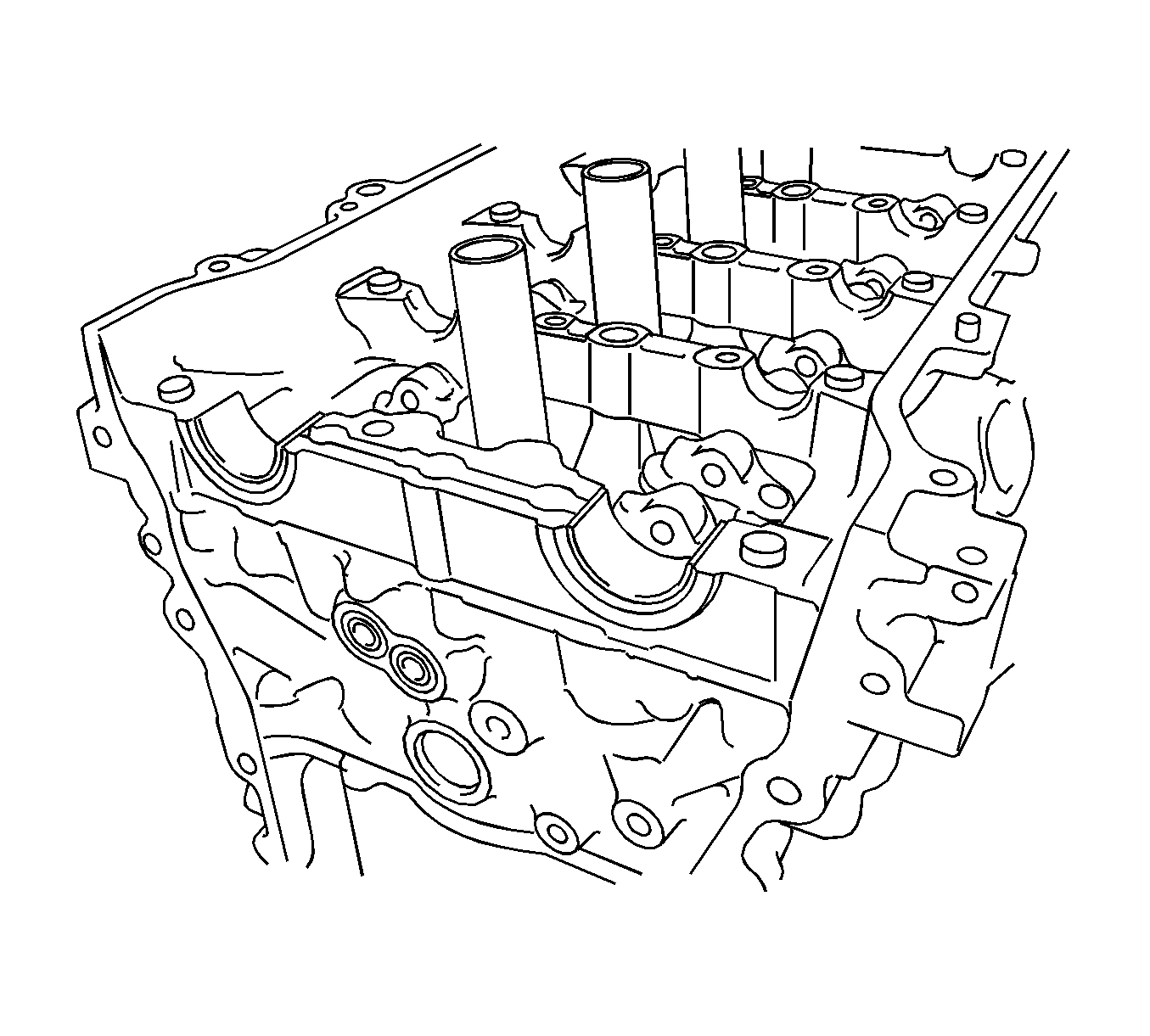
- Remove the 2 camshaft bearings from the cylinder head.
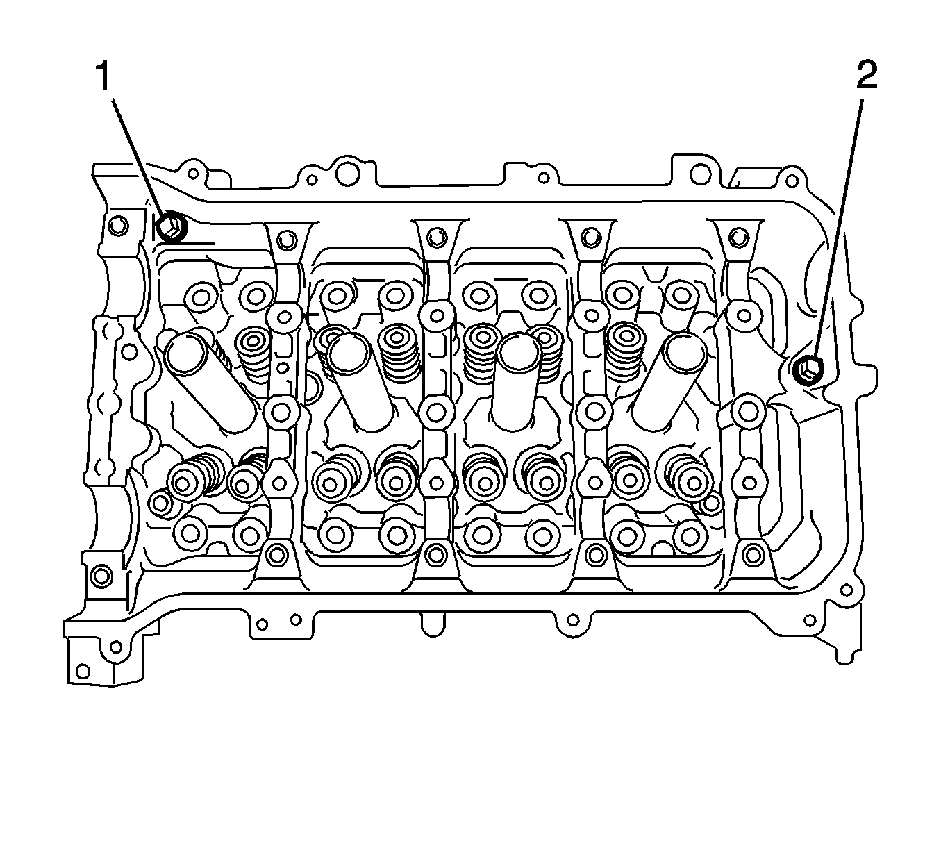
- Remove the 2 bolts (1, 2).
- Remove the camshaft housing assembly by prying between the cylinder head and camshaft housing with a screwdriver (1).
- Inspect the valve rocker arm assembly.
- Inspect the valve lash adjuster assembly.
- Clean the camshaft housing and cylinder head.
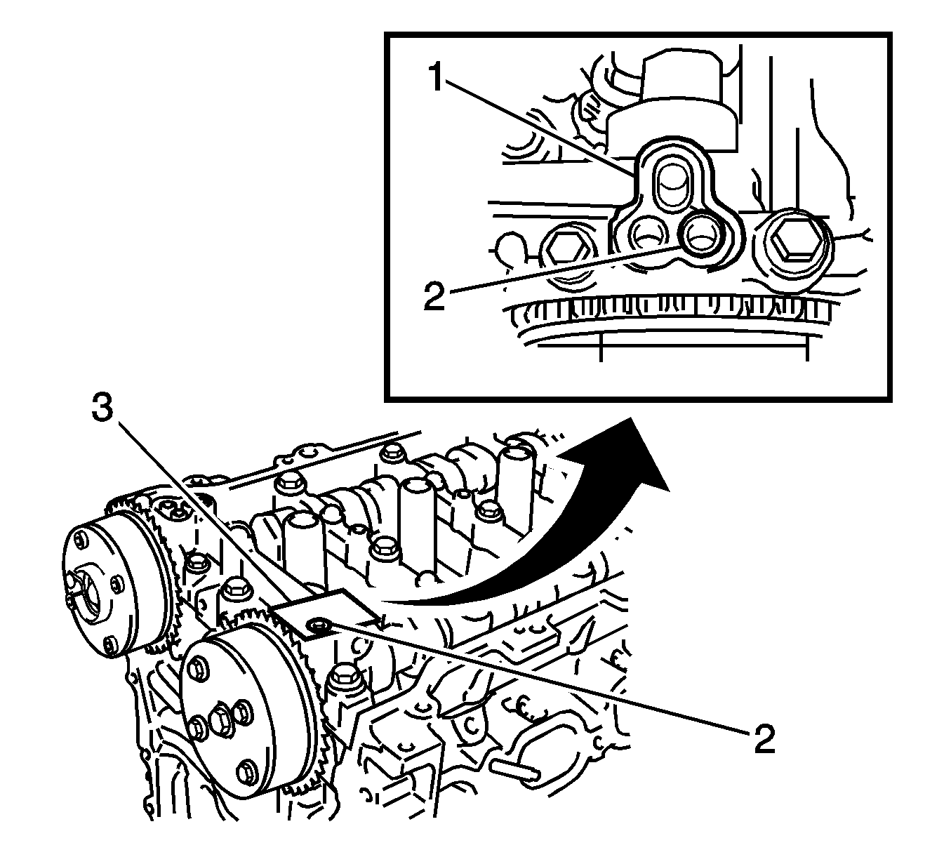
Note: Be sure to cover the oil hole completely because air leaks due to insufficient sealing will prevent the lock pin from being released.
Note:
• If air leaks out, reattach the adhesive tape. • Cover the oil hole with a shop rag or piece of cloth when applying air pressure to prevent oil from spraying.
Note: Depending on the air pressure applied, the camshaft timing gear assembly may turn in the advanced direction without assistance by hand.
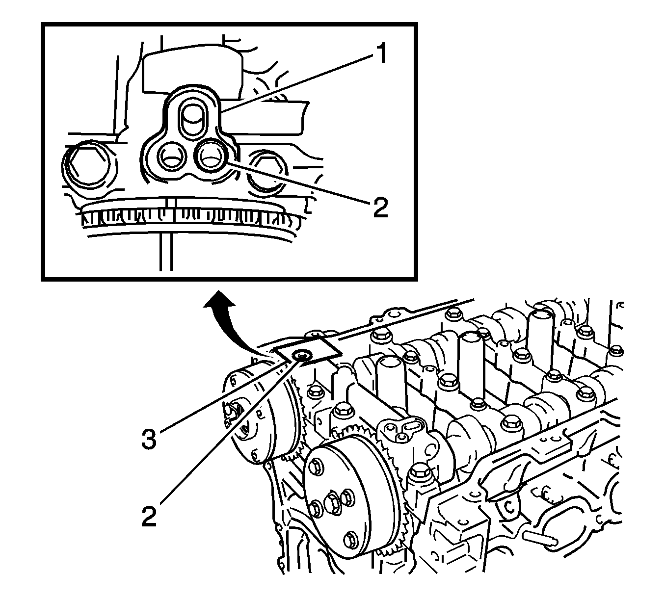
Note: Be sure to cover the oil hole completely because air leaks due to insufficient sealing will prevent the lock pin from being released.
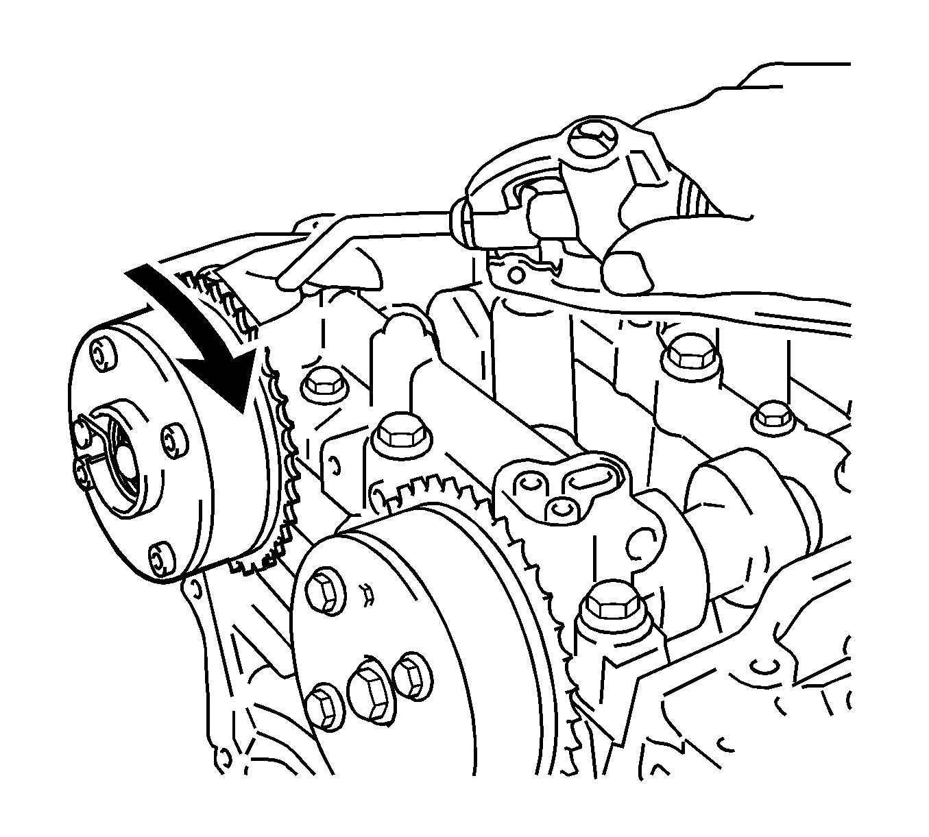
Note:
• If air leaks out, reattach the adhesive tape. • Cover the oil hole with a shop rag or piece of cloth when applying air pressure to prevent oil from spraying.
Note: Be sure to keep the camshaft timing exhaust gear in the retard direction using a screwdriver. If the gear is released, it will return to the most advanced position automatically due to force from the spring.
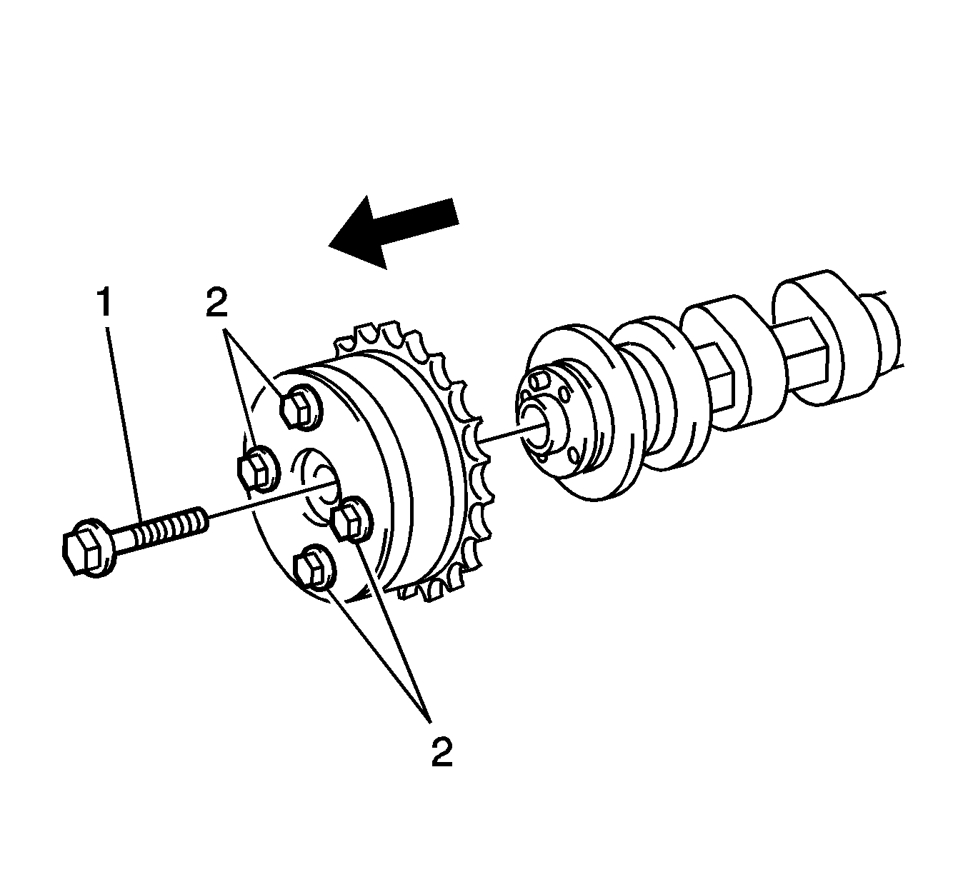
Note:
• Before removing the camshaft timing gear, make sure that the lock pin has been released. • Be sure not to remove the other 4 bolts (2). • Keep the camshaft timing gear assembly horizontal while removing it from the camshaft.
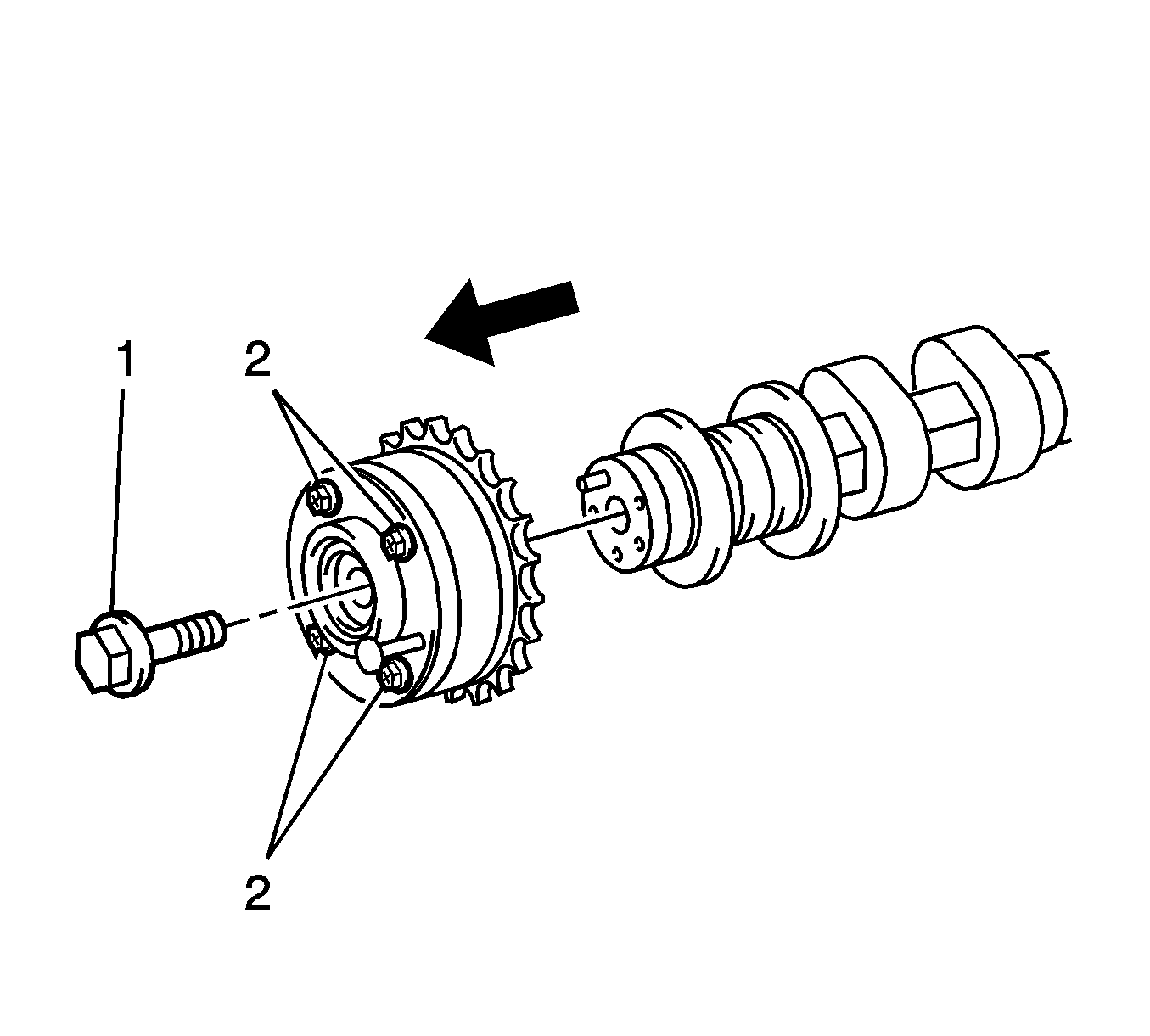
Note:
• Be sure not to remove the other 4 bolts (2). • Keep the camshaft timing exhaust gear assembly horizontal while removing it from the camshaft.
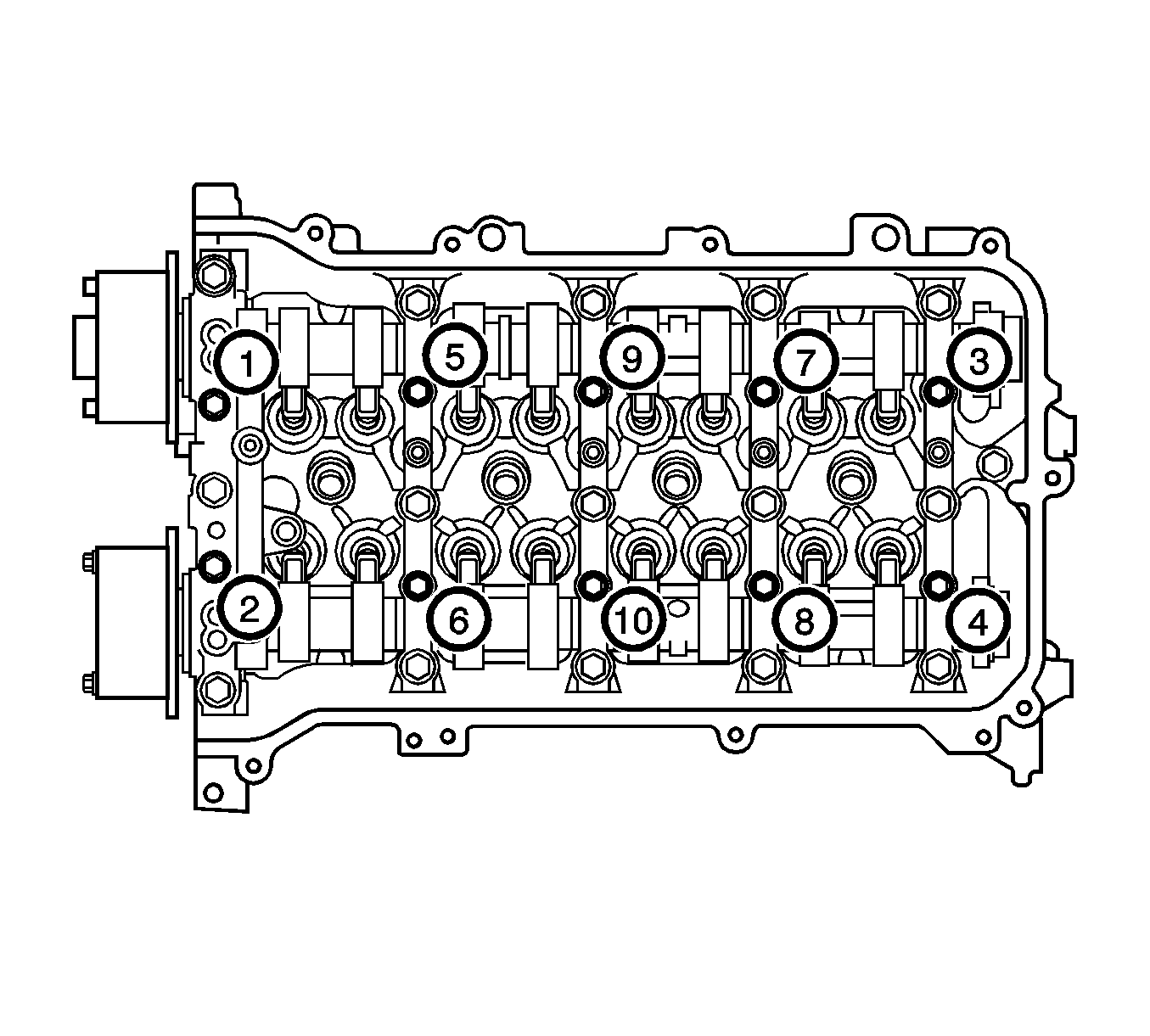
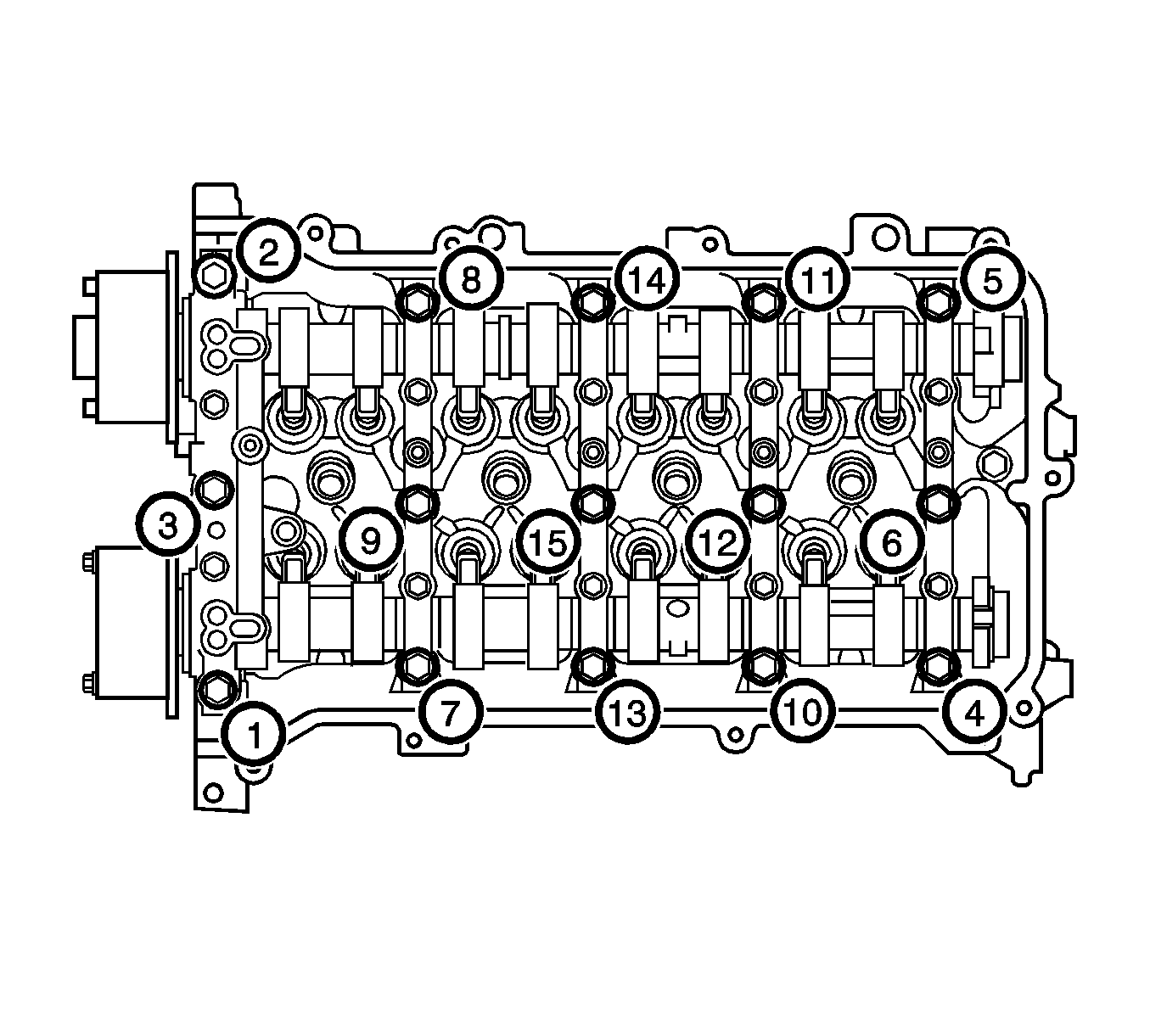
Note: Uniformly loosen the bolts while keeping the camshaft level.
Note: Arrange the removed parts in the correct order.
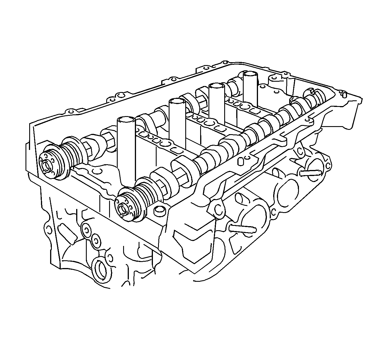
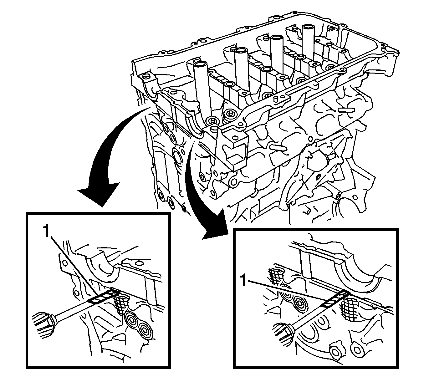
Note: Tape the screwdriver tip before use.
Installation Procedure
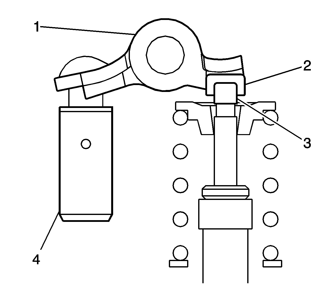
- Install the valve lash adjuster assembly (2).
- Install the valve rocker arm assembly (1).
- Install the 2 camshaft bearings after cleaning both surfaces of the bearings.
- Using vernier calipers (1), measure the distance between the bearing cap edge and the camshaft bearing edge.
- Clean both surfaces of the bearings.
- Install the 2 camshaft bearings.
- Using vernier calipers (1), measure the distance between the bearing cap edge and the camshaft bearing edge.
- Clean the camshaft journals.
- Apply a light coat of engine oil to the camshaft journals, camshaft housings and bearing caps.
- Install the exhaust camshaft to the camshaft housing.
- Clean the camshaft journals.
- Apply engine oil to the camshaft journals, camshaft housings and bearing caps.
- Install the intake camshaft to the camshaft housing.
- Ensure the marks and numbers on the camshaft bearing caps (1-4) and place them in each proper position and direction.
- Install the 10 bolts in the order shown and tighten to 16 N·m (12 lb ft).
- Install the camshaft housing sub-assembly.
- Make sure that the valve rocker arm (1) is installed as shown in the illustration.
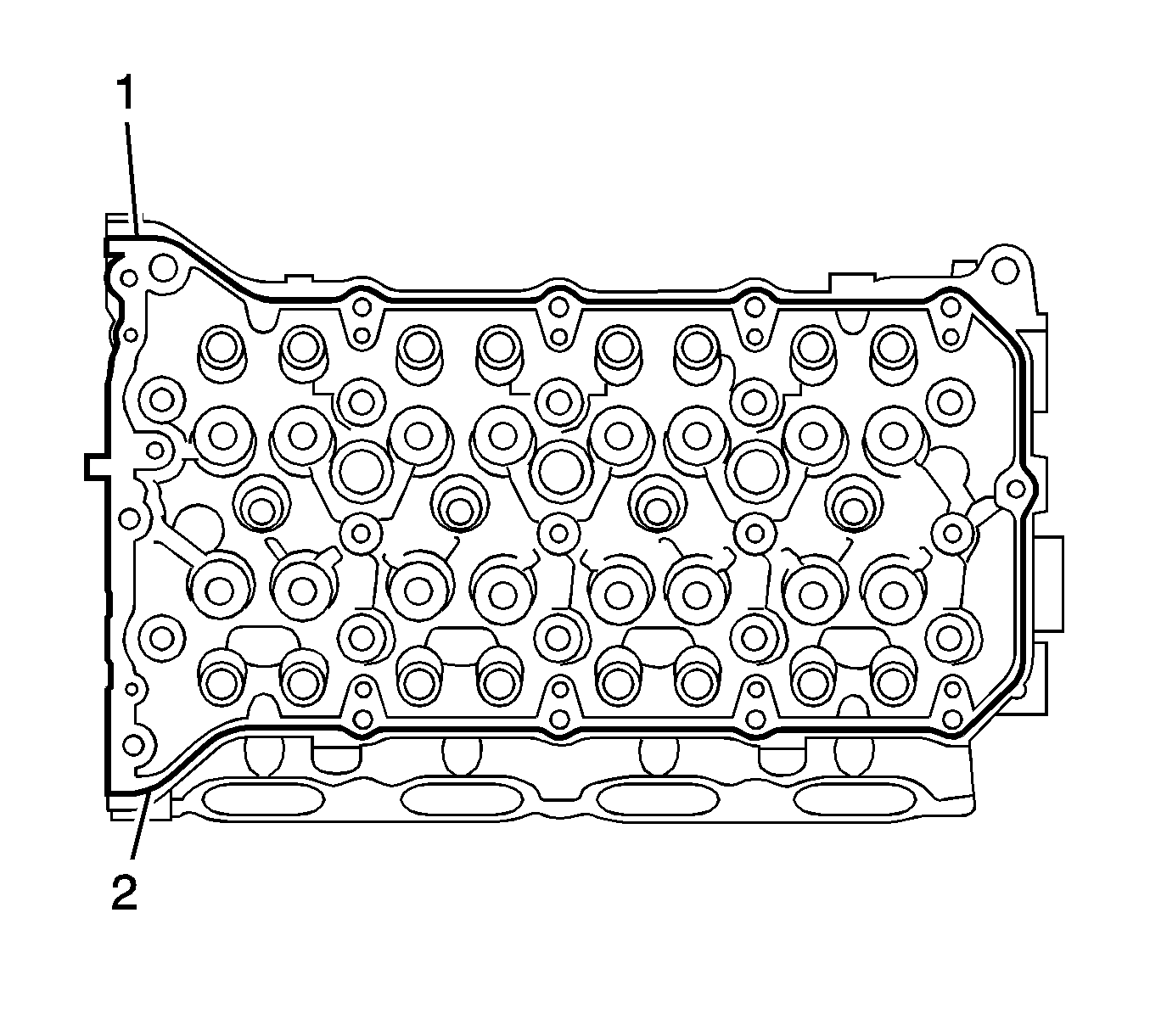
- Apply a continuous bead of sealant (1), diameter: 3.5-4.0 mm (0.138-0.158 in), as shown in the illustration, Three Bond 1217B, or equivalent, GM part number 12378521 (Canadian part number 88901148).
- Set the intake camshaft and the exhaust camshaft.
- Install the camshaft housing and tighten the 17 bolts in the order shown and tighten to 27 N·m (20 lb ft).
- Install camshaft timing gear assembly.
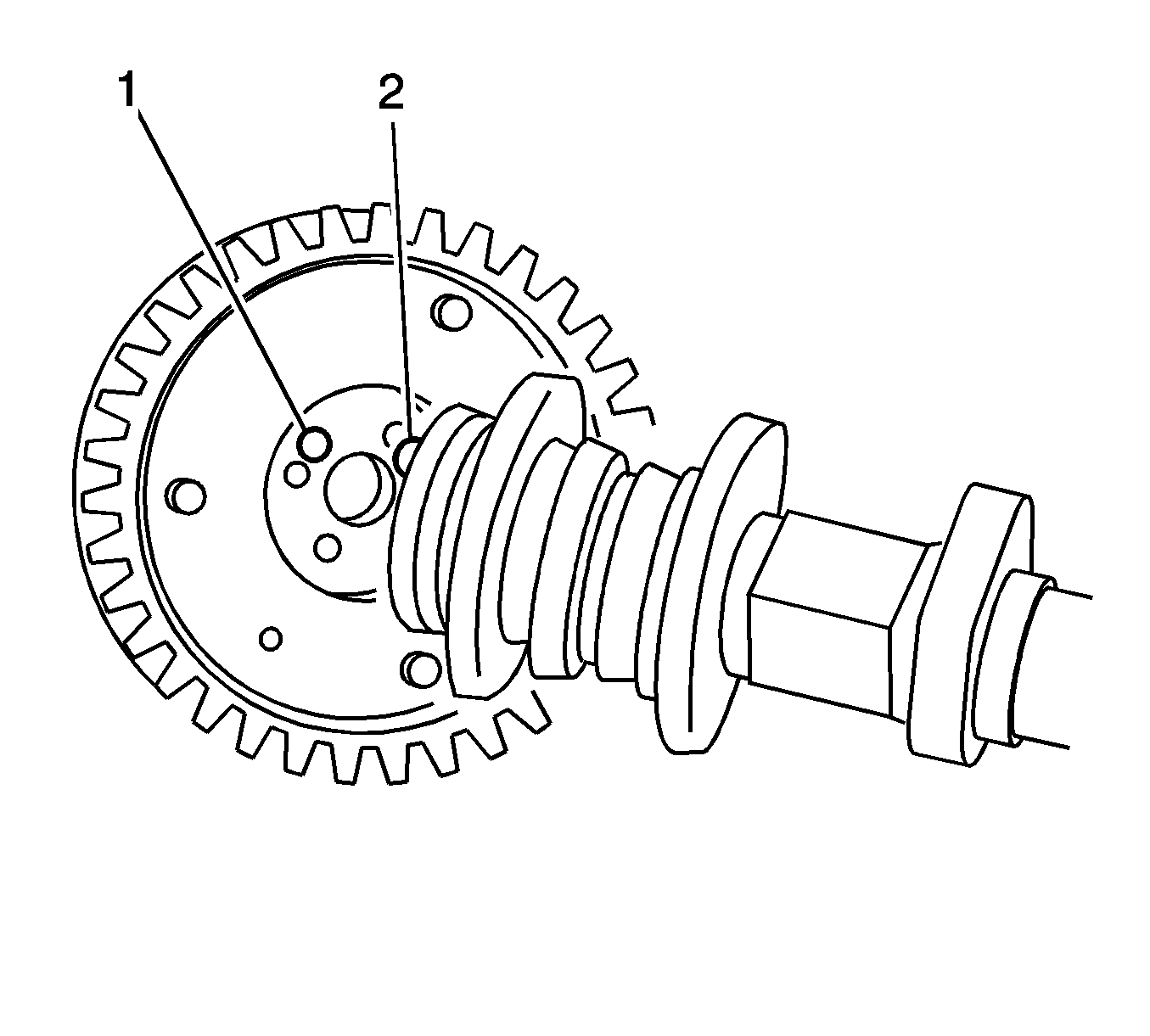
- Check that the knock pin (1) is installed on the camshaft.
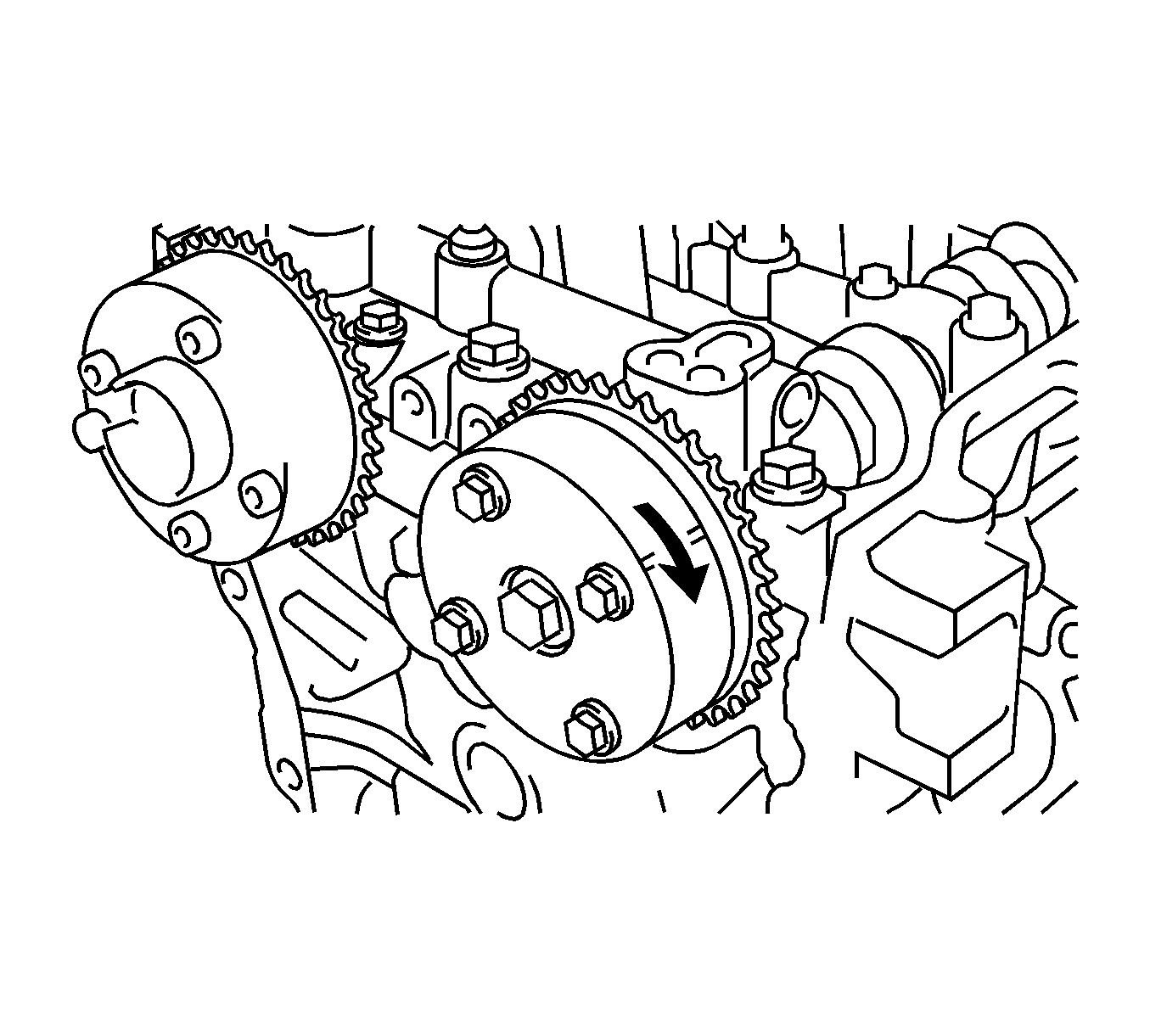
- Put the camshaft timing gear and camshaft together with the straight pin and key groove misaligned, as shown in the illustration.
- Turn the camshaft timing gear as shown in the illustration while pushing it gently against the camshaft. Push further at the position where the pin (1) fits into the groove (2).
- Measure the clearance between the gear (1) and the camshaft (2).
- Install the flange bolt (1) with the camshaft timing gear fixed in place and tighten to 54 N·m (40 lb ft).
- Check that the camshaft timing gear can move in the retard direction (clockwise) and is locked in the most retarded position.
- Install the camshaft timing exhaust gear assembly.
- Check that the knock pin is installed on the camshaft.
- Put the camshaft timing exhaust gear and camshaft together by aligning the key groove (1) and straight pin (2).
- Lightly press the gear against the camshaft, and turn the gear. Push further at the position where the pin enters the groove.
- Check that there is no clearance between the gear flange and the camshaft.
- Install the flange bolt (1) with the camshaft timing exhaust gear fixed and tighten to 54 N·m (40 lb ft).
- Make sure that the camshaft timing exhaust gear is locked.
- Install the timing gear chain vibration damper.
- Install the oil pump chain vibration damper.
- Install the chain assembly.
- Install the chain tensioner slipper.
- Install the timing chain cover oil seal.
- Install the timing chain cover assembly. Refer to Timing Chain Housing Installation.
- Install the crankshaft pulley.
- Install the chain tensioner assembly. Refer to Timing Chain Tensioner Installation.
- Install the cylinder head cover assembly. Refer to Camshaft Cover Installation.
- Install the radio setting condenser.
- Install the thermostat.
- Install the inlet water.
- Install the inlet water hose.
- Install the water by-pass pipe.
- Install the water by-pass hoses.
- Install the ventilation hose.
- Install the exhaust manifold. Refer to Exhaust Manifold Installation.
- Install the oil level dipstick sub-assembly. Refer to Oil Level Indicator Tube Replacement.
- Install the ignition coil assembly.
- Install the fuel injector assembly.
- Install the delivery pipe spacer.
- Install the fuel delivery pipe assembly.
- Install the fuel tube assembly.
- Install the intake manifold. Refer to Intake Manifold Installation.
- Remove the engine stand.
- Install the engine assembly with transaxle. Refer to Engine Replacement.
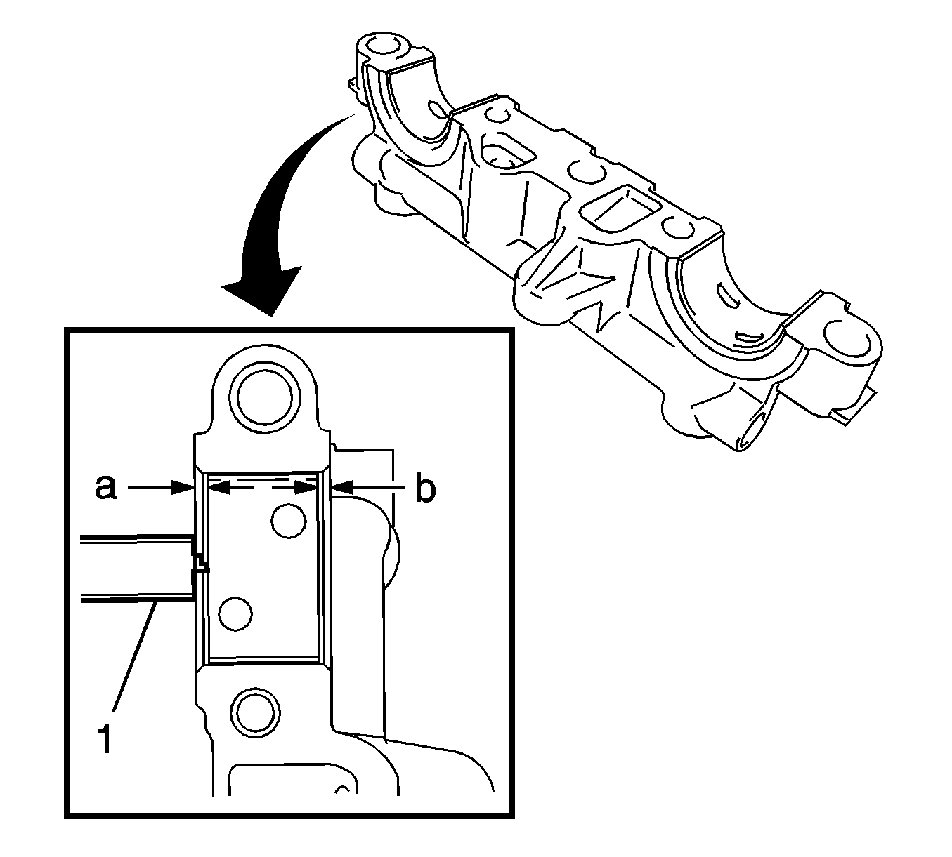
Note: Position the bearings to the center of the bearing cap by measuring dimensions A and B.
Specification
Dimension (A-B): 0.7 mm (0.0276 in) or less
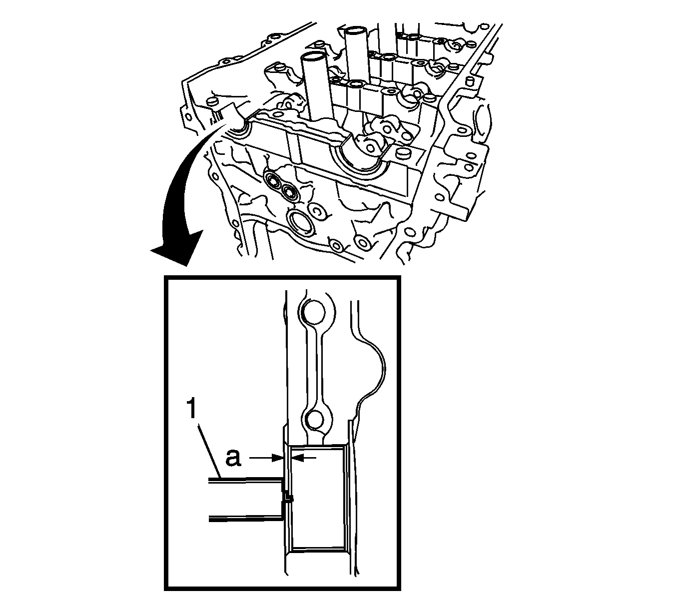
Note: Position the bearings to the center of the bearing cap by measuring dimension A.
Specification
Dimension (A): 1.05-1.75 mm (0.0413-0.0689 in.)


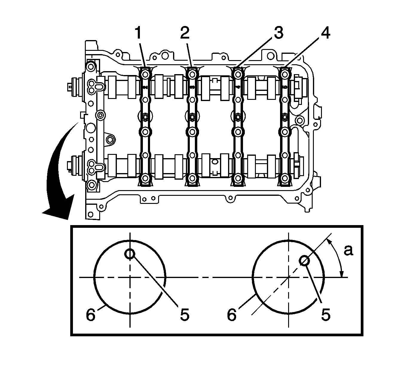
Note: Make sure that the knock pin (5) of the camshafts (6) are positioned as shown in the illustration.
Caution: Refer to Fastener Caution in the Preface section.

Note:
• Remove any oil from the contact surface. • Install the camshaft housing assembly within 3 minutes and tighten the bolts within 15 minutes after applying seal packing. • Do not start the engine for at least 2 hours after installing.
Note:
• After installing the camshaft housing, make sure that the cam lobes are positioned as shown. • If any of the bolts are loosened during installation, remove the camshaft housing, clean the installation surfaces, and reapply seal packing. • If the camshaft housing is removed because any of the bolts are loosened during installation, make sure that the previously applied seal packing does not enter any oil passages. • After installing the camshaft housing, wipe off any seal packing that seeped out from between the housing and the cylinder head.
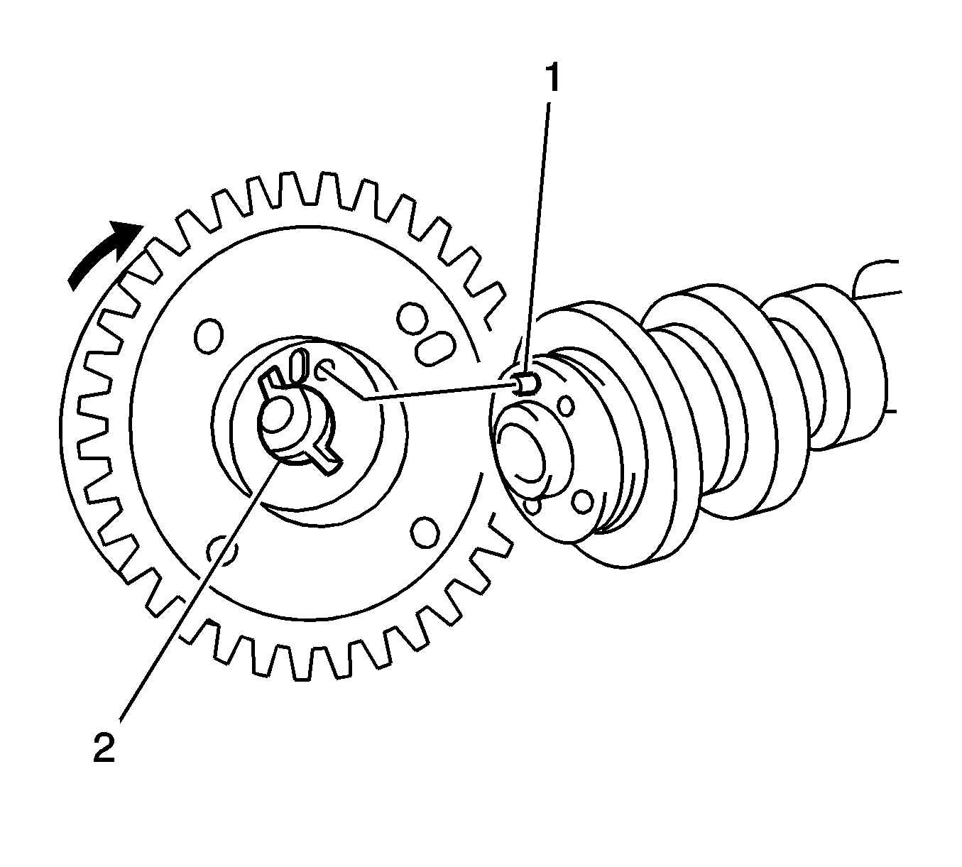
Note: Do not forcefully push in the camshaft timing gear assembly. This may cause the camshaft knock pin tip to damage the installation surface of the camshaft timing gear assembly.
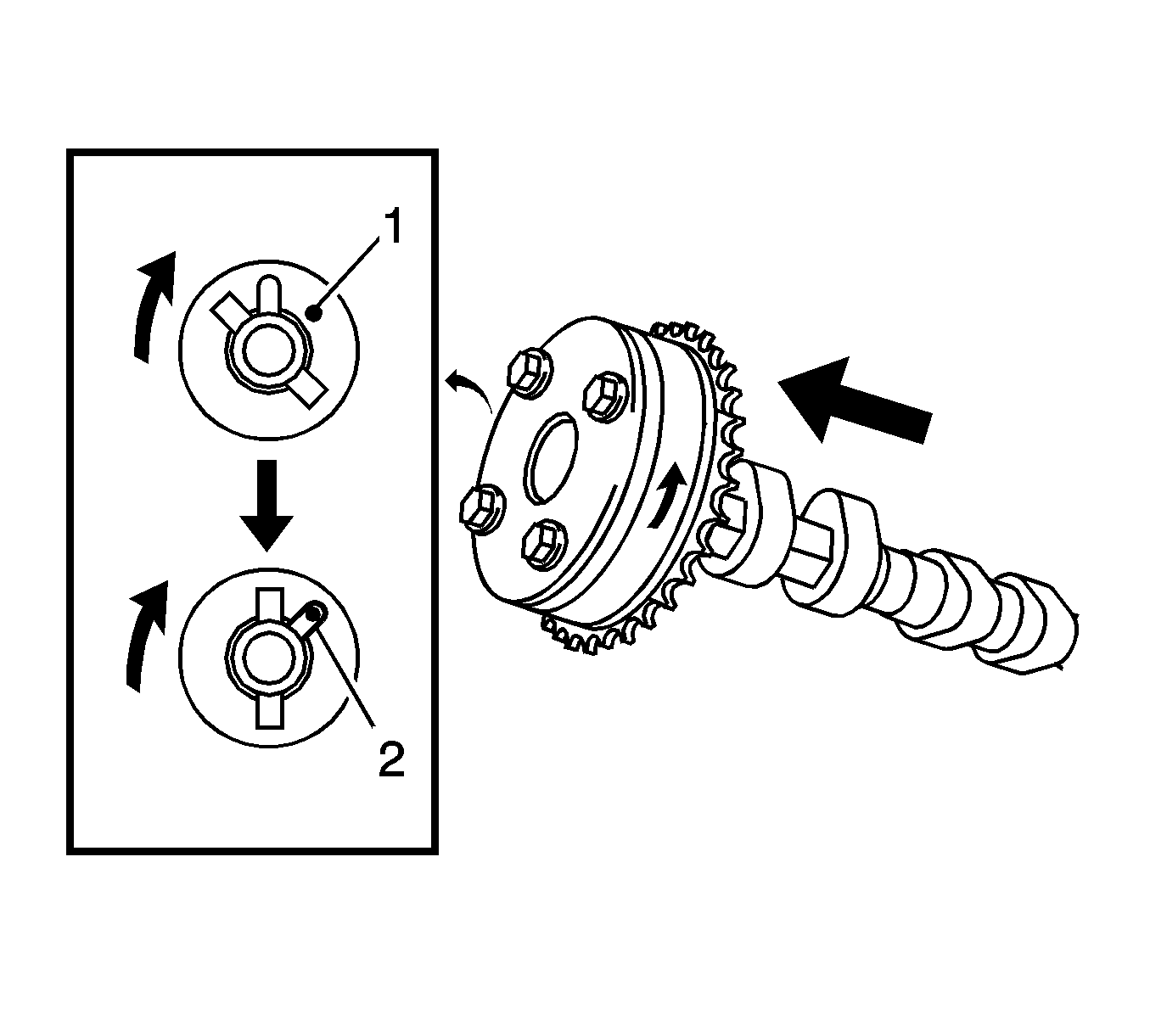
Note: Do not turn the camshaft timing gear in the retard direction (clockwise).
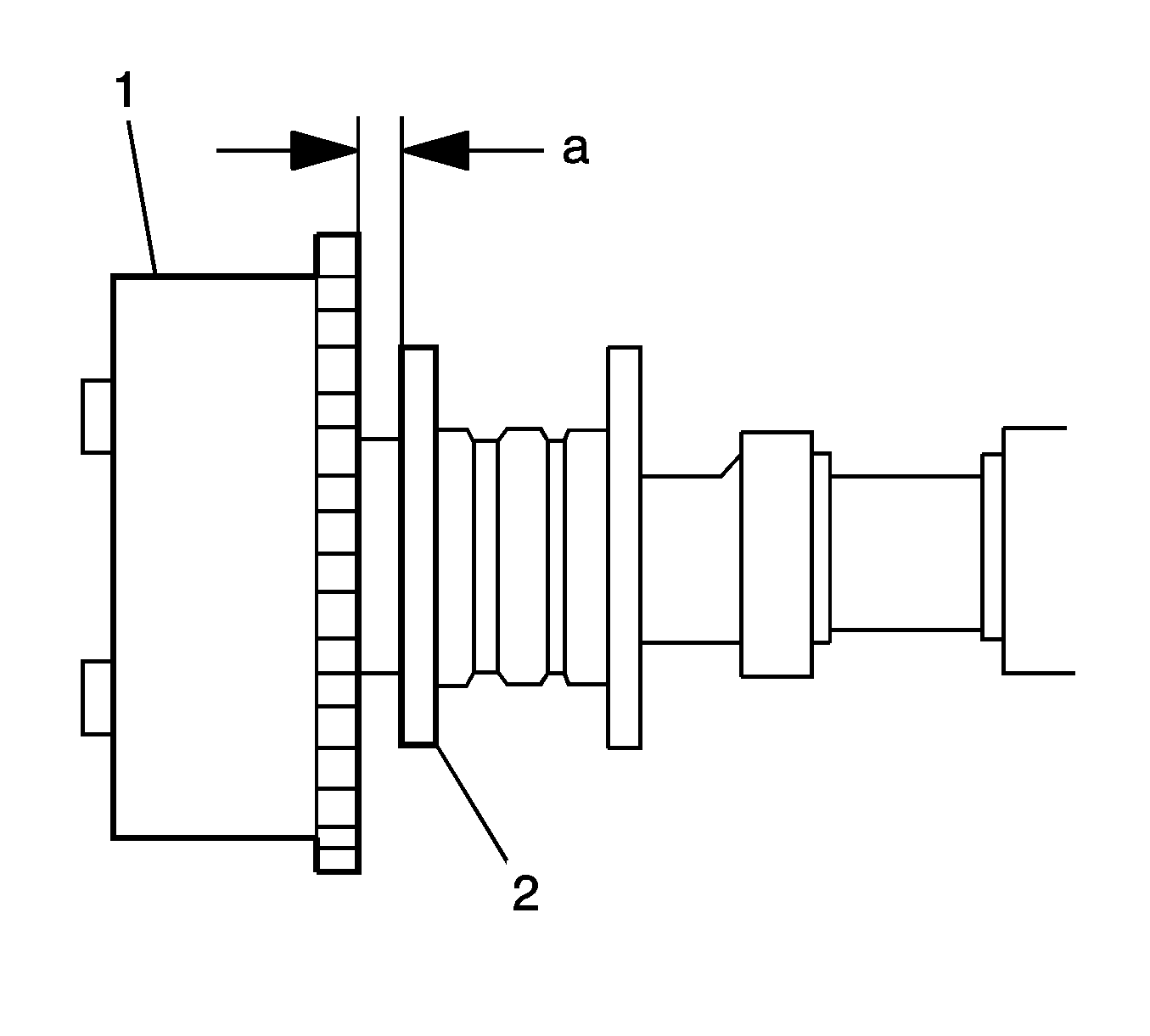
Specification
Clearance: 0.1-0.4 mm (0.004-0.016 in.)
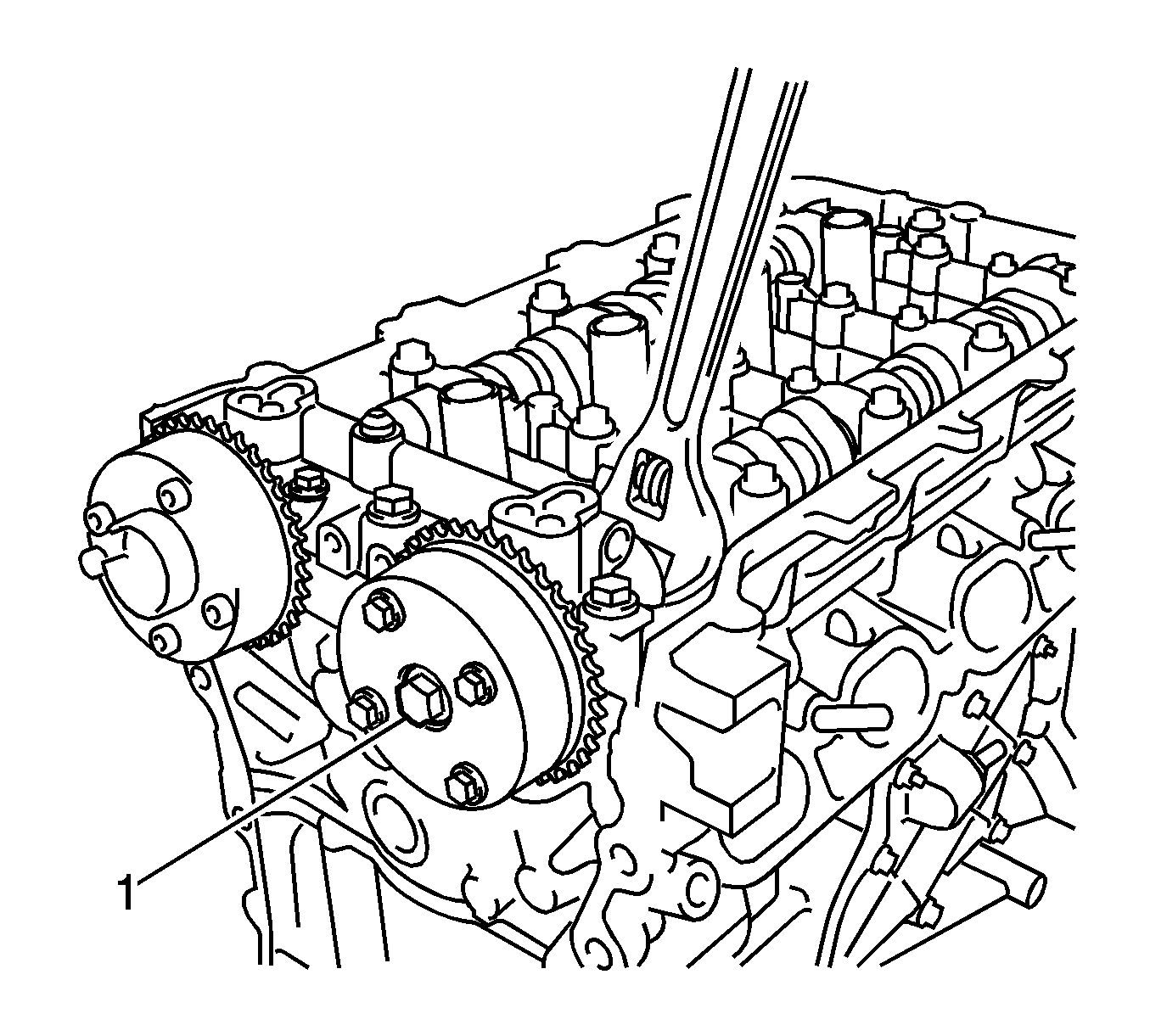
Note: Be sure not to turn the camshaft timing exhaust gear in the retard direction (clockwise).
