Caution: Refer to Fastener Caution in the Preface section.
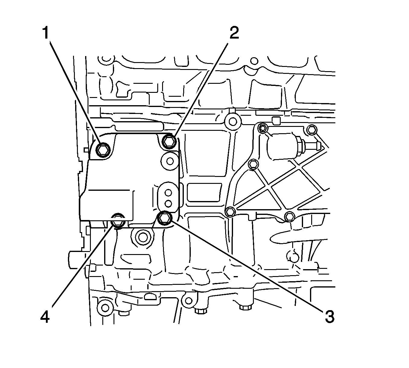
- Install the generator bracket with the 4 bolts (1-4) and tighten to
21 N·m (16 lb ft).
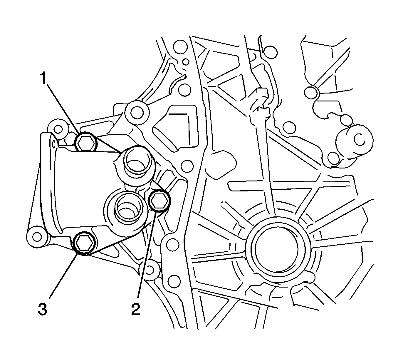
- Install the inlet water housing with the 3 bolts (1-3) and tighten to
21 N·m (16 lb ft).
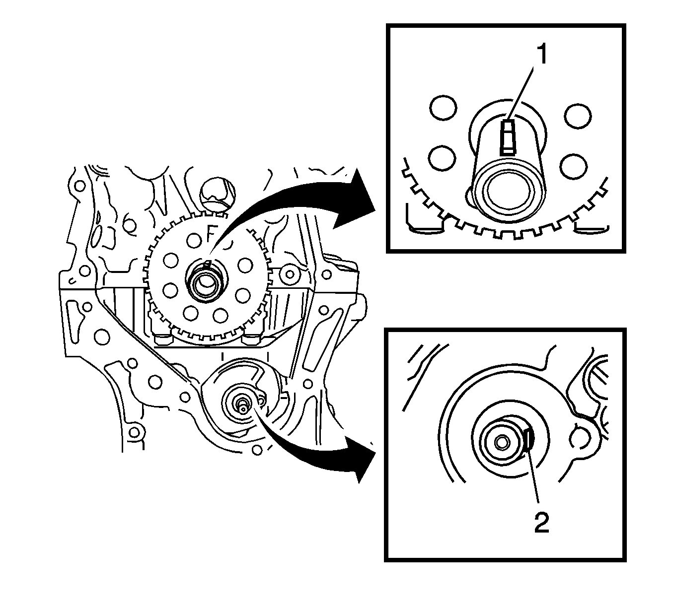
- Set the crankshaft key (1).
- Turn the drive shaft (2) so that the cutout faces right horizontal position.
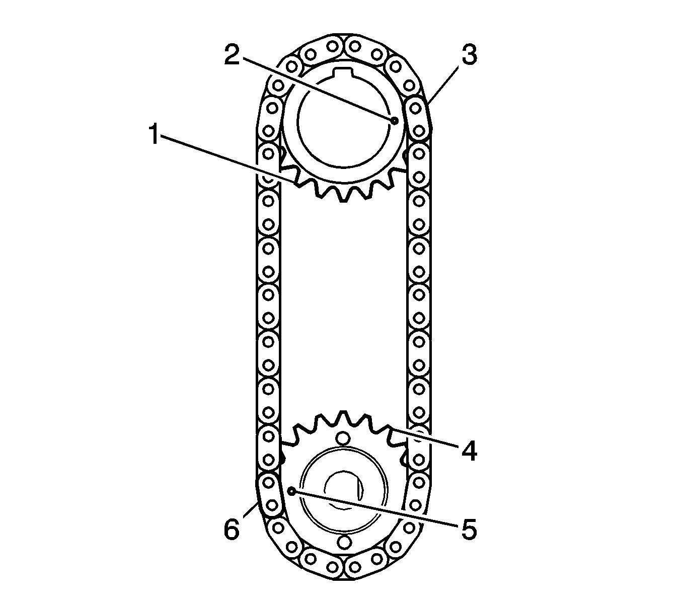
- Align the yellow mark links (3, 6) with the timing marks (2, 5) of each gear.
- Install the sprockets onto the crankshaft and oil pump shaft with the chain on the gears.
- Hand tighten the oil pump drive shaft sprocket with the nut.
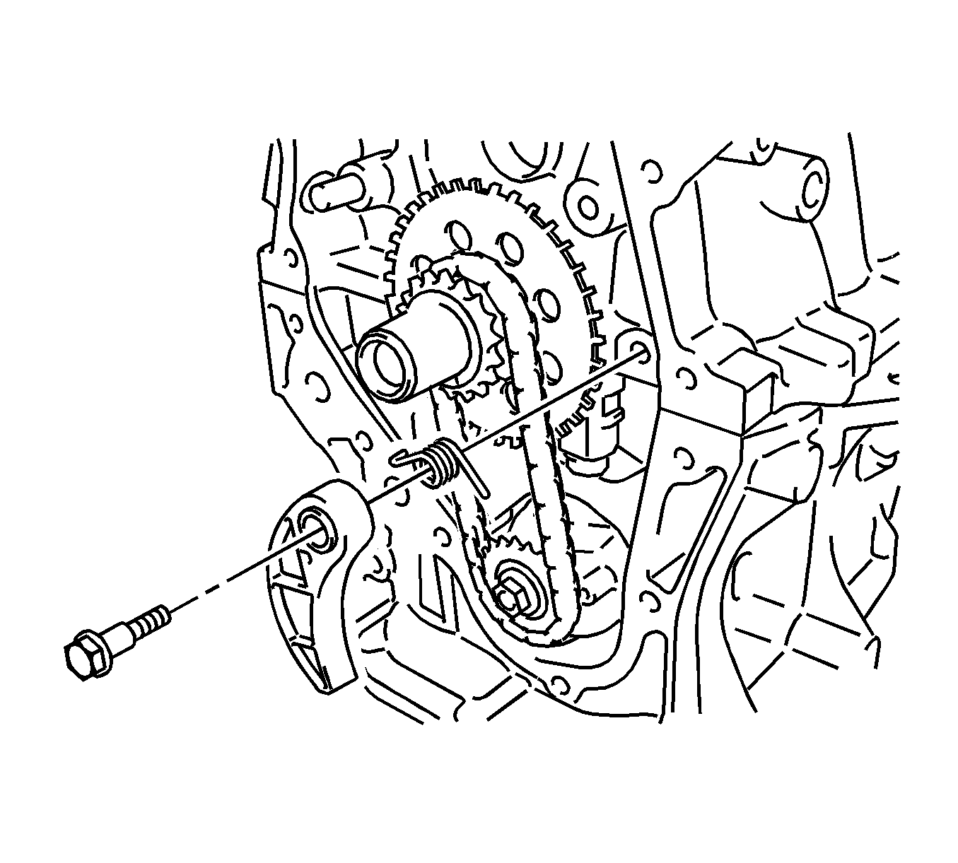
- Insert the damper spring into the adjusting hole, and then install the chain tensioner plate with the bolt and tighten to
10 N·m (7 lb ft).
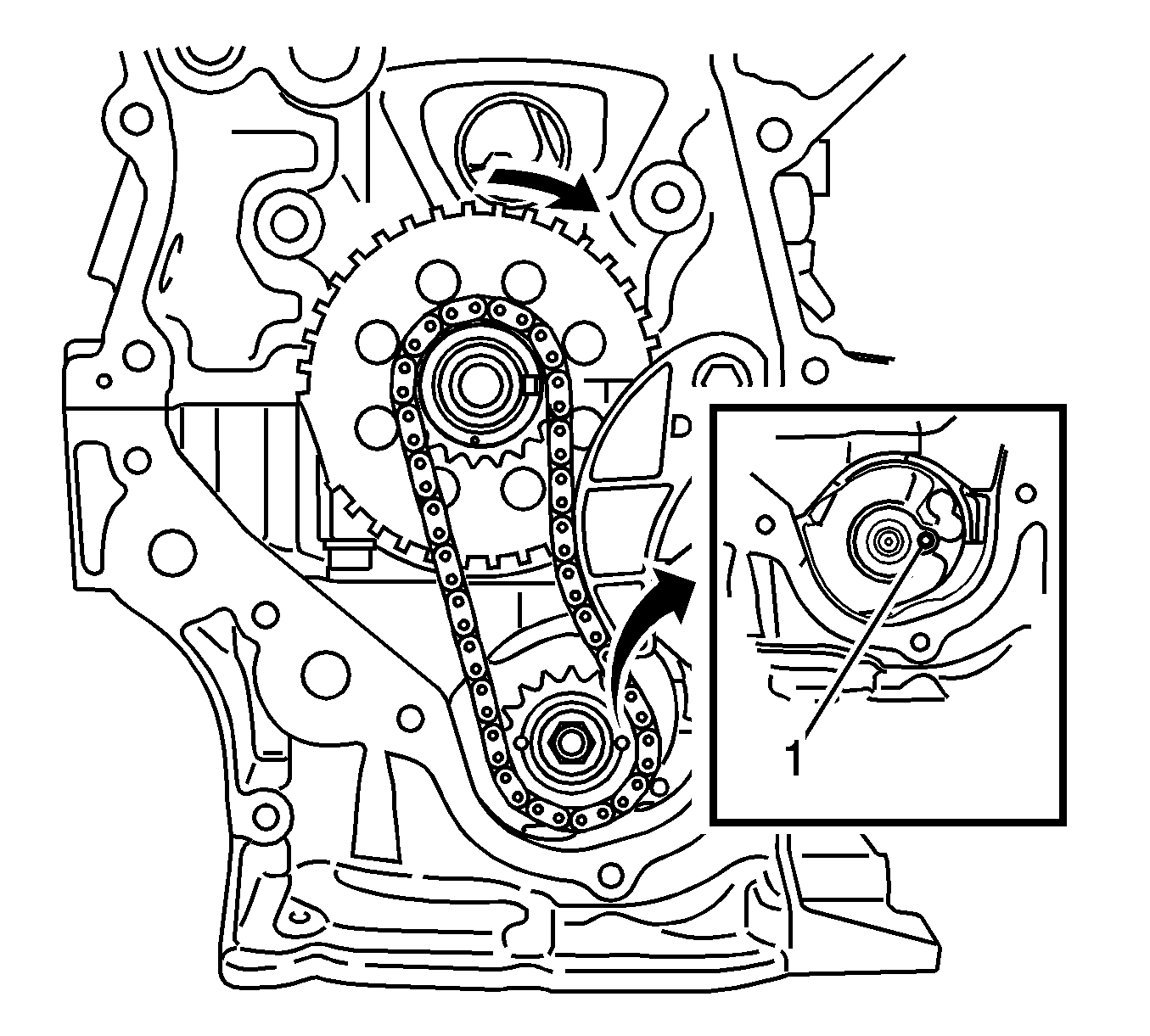
- Align the adjusting hole of the oil pump drive shaft sprocket (1) with the groove of the oil pump.
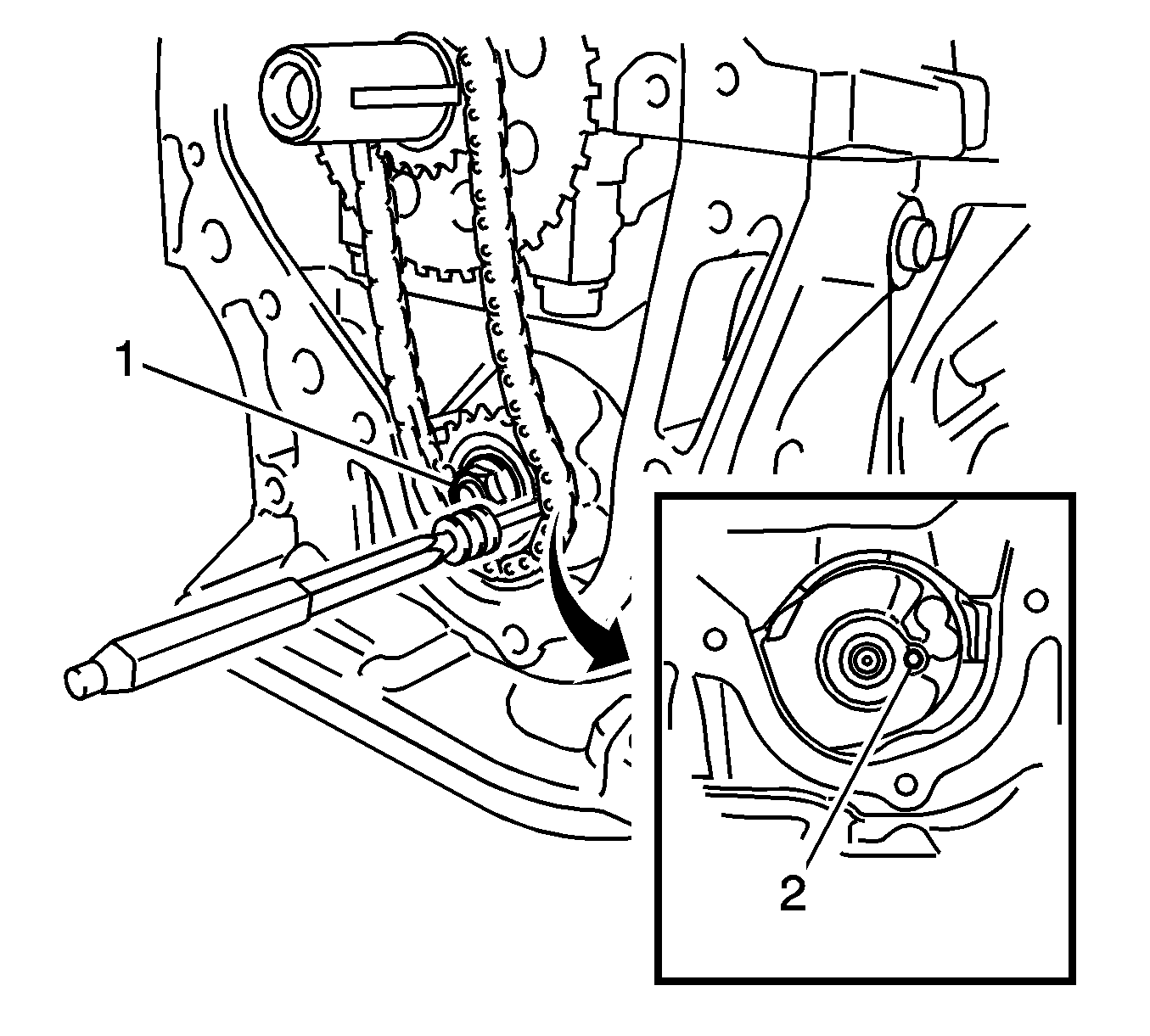
- Insert a pin punch (3 mm) into the adjusting hole (2) of the oil pump drive shaft gear to lock the gear in position,
and then tighten the nut (1) to
28 N·m (21 lb ft).
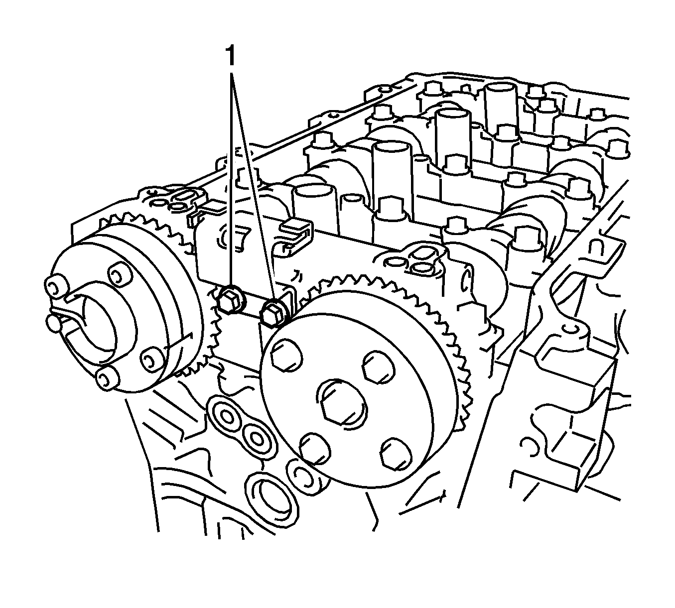
- Install the chain vibration damper with the 2 bolts (1) and tighten to
10 N·m (7 lb ft).
- Install the chain assembly.
- Install the chain tensioner slipper.
- Apply MP grease to the lip of the oil seal.
- Remove any old sealant material and be careful not to drop any oil on the contact surfaces of the timing chain cover assembly, cylinder head, and cylinder block.
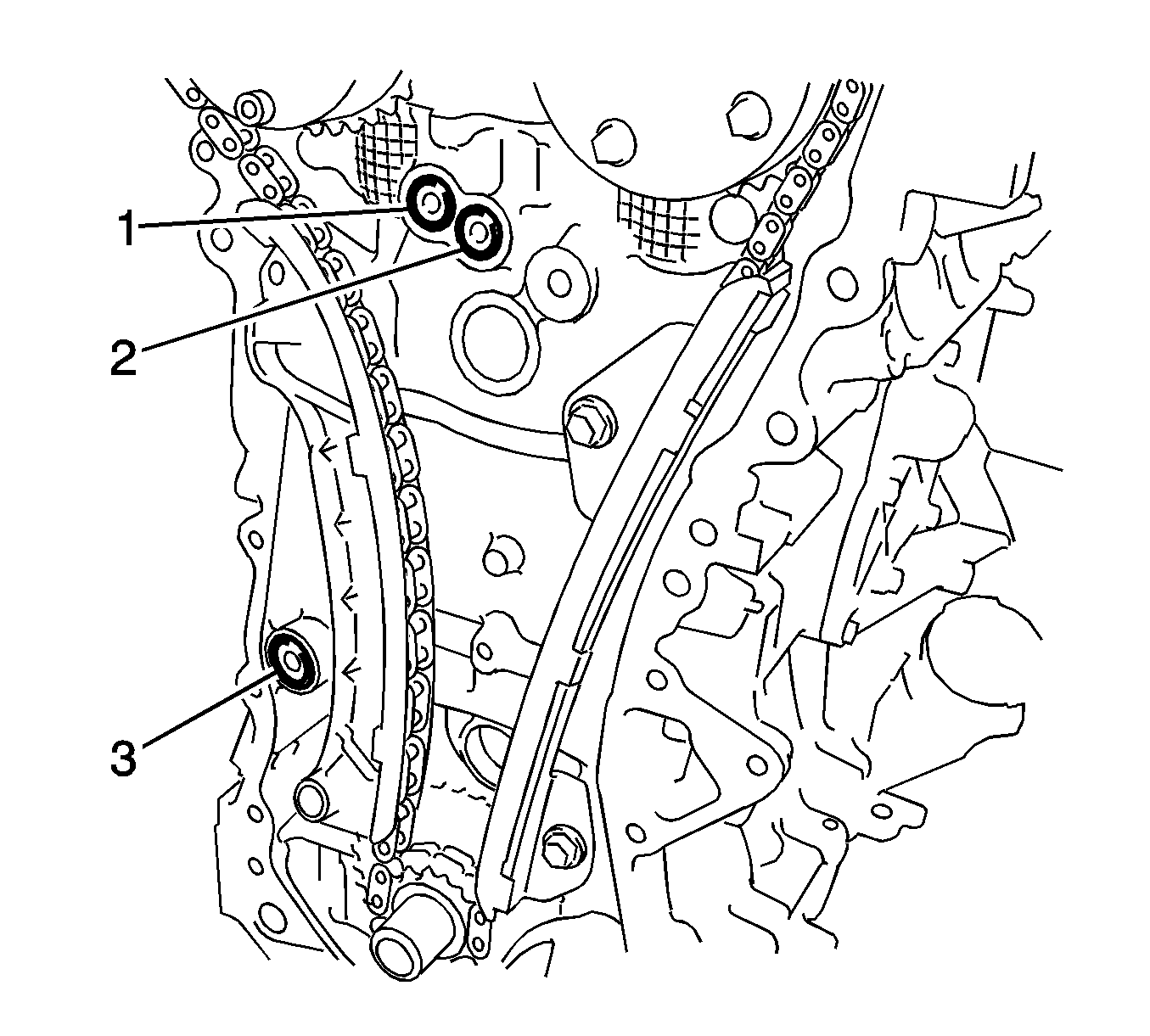
- Install the 3 new O-rings (1-3).
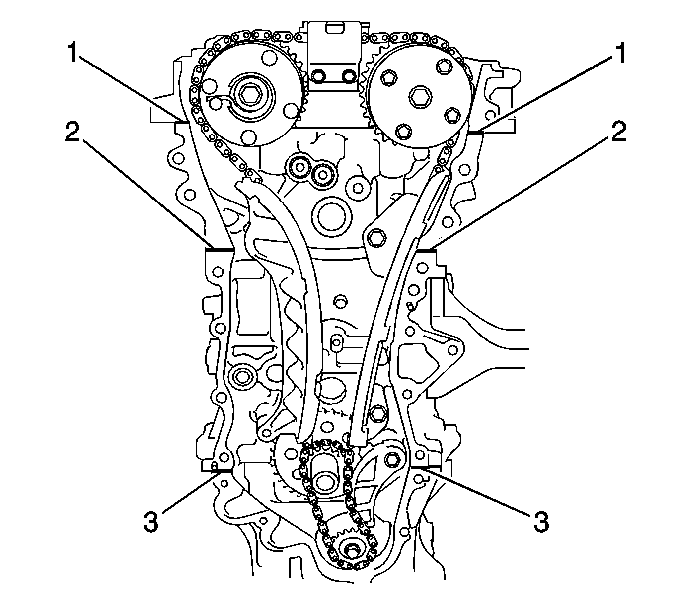
Note:
| • | Remove any oil from the contact surfaces. |
| • | Install the chain cover within 3 minutes after applying sealant. |
| • | Do not start the engine for at least 2 hours after installing the timing chain cover sub-assembly. |
- Apply Three Bond 1217B, or equivalent, GM part number 12378521 (Canadian part number 88901148) to the parting lines of the camshaft housing (1), cylinder head (2) and lower crankcase (3)
Note:
| • | When the contact surfaces are wet, wipe them with oil-free cloth before applying sealant. |
| • | Install the timing chain cover sub-assembly within 3 minutes and tighten the bolts within 15 minutes after applying sealant. |
| • | Do not start the engine for at least 2 hours after installing. |
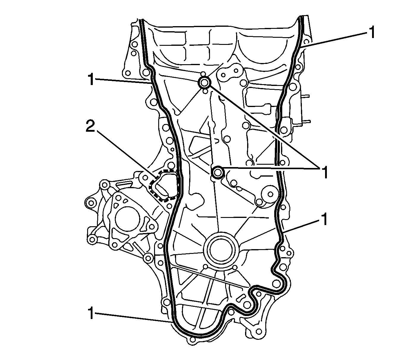
- Apply sealant to the timing chain cover in a continuous line as follows:
Continuous Line Area (1)
| • | Sealant Diameter - 3.0 mm (0.118 in) |
| • | Application Position form Inside Seal Line - 2.5 mm (0.098 in) |
| • | Sealant - Three Bond 1207B or equivalent |
Dashed Line Area (2)
| • | Sealant Diameter - 4.0 mm (0.156 in) |
| • | Application Position form Inside Seal Line - 3.0 mm (0.118 in) |
| • | Sealant - Three Bond 1207B or equivalent |
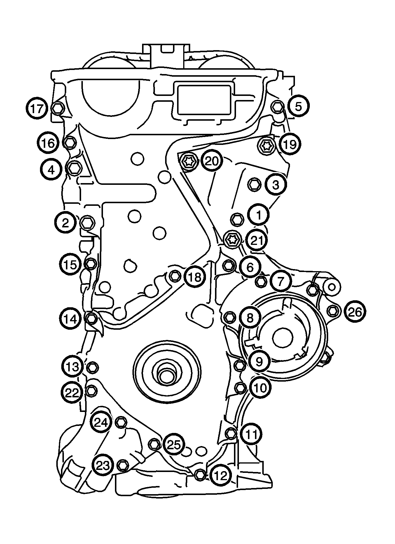
- Hand install the timing chain cover assembly with the 19 bolts.
Note: Remove any oil from the contact surfaces.
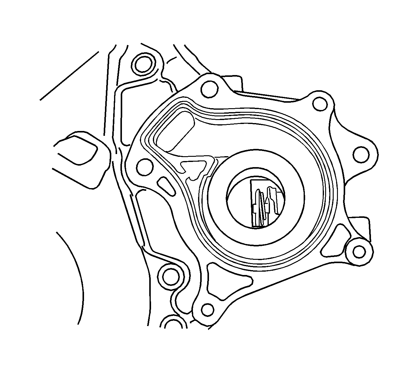
- Install a new water pump gasket.
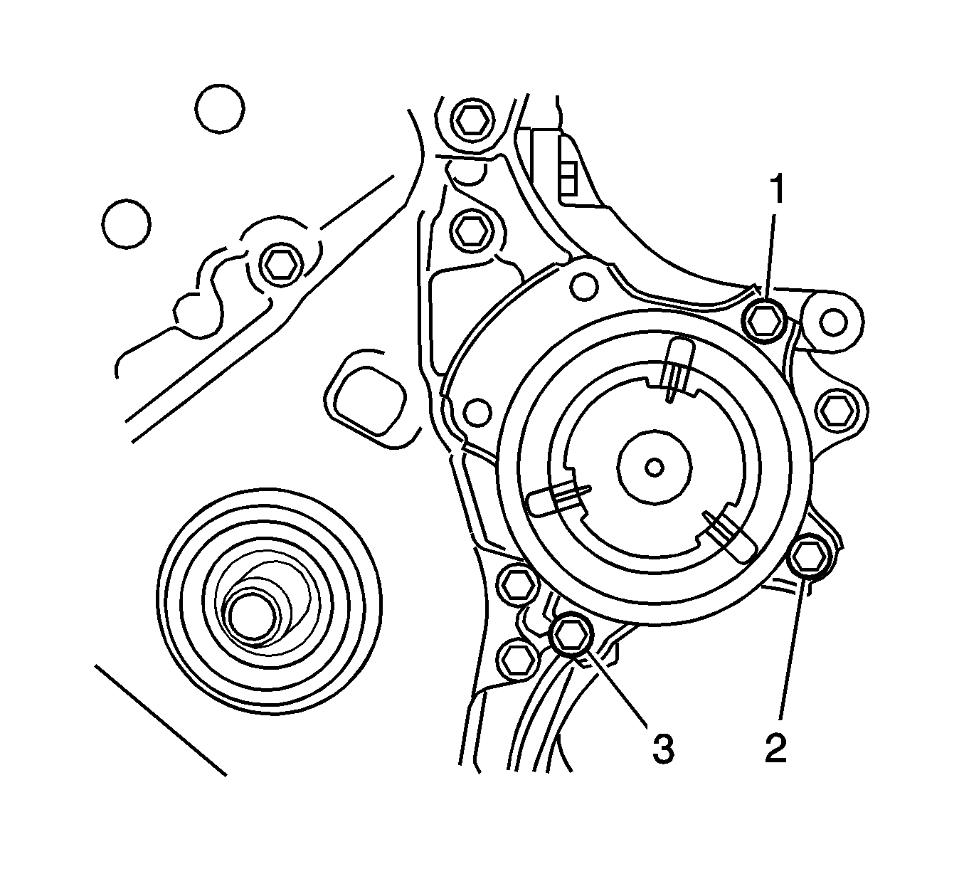
- Install the water pump with the 3 bolts (1, 2, 3) and tighten to
24 N·m (18 lb ft).
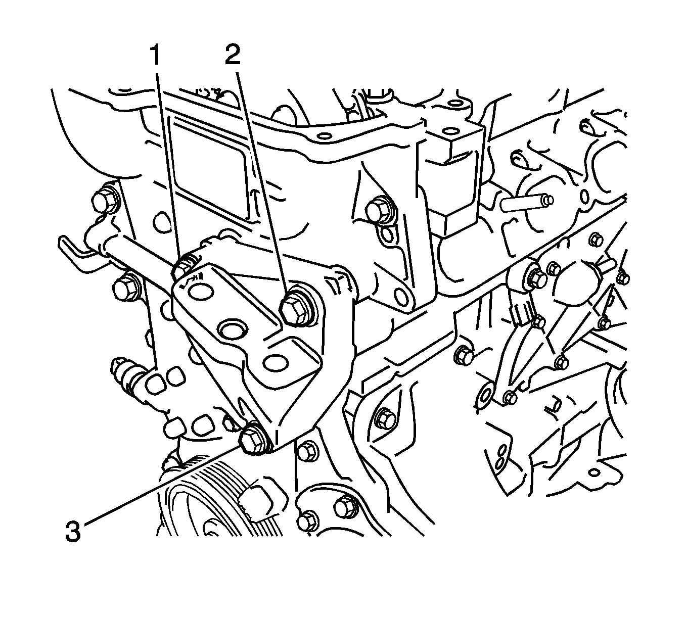
- Install the mounting bracket within 10 minutes after installing the timing chain cover assembly.
- Hand tighten the engine mounting bracket with the 3 bolts (1, 2, 3).
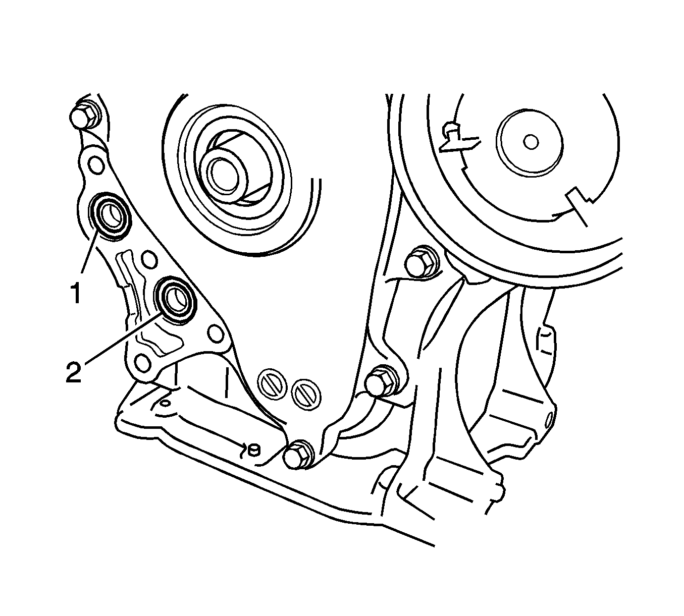
- Install 2 new O-rings (1, 2).
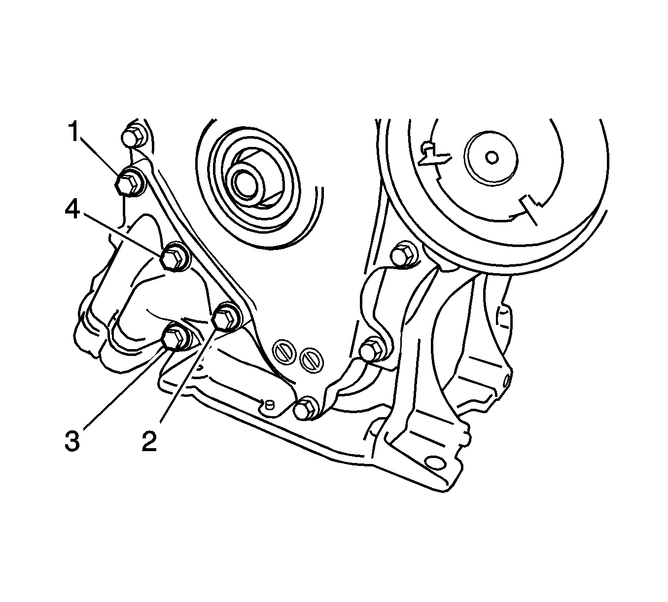
- Install the oil filter bracket within 10 minutes after installing the chain cover.
- Temporarily tighten the oil filter bracket with the 4 bolts (1-4).
- Apply Three Bond 1324 or equivalent to the threads of the bolt 5.
- Install the chain cover within 3 minutes and tighten the bolts within 15 minutes after applying the sealant.
- Torque the bolts in the above sequence.
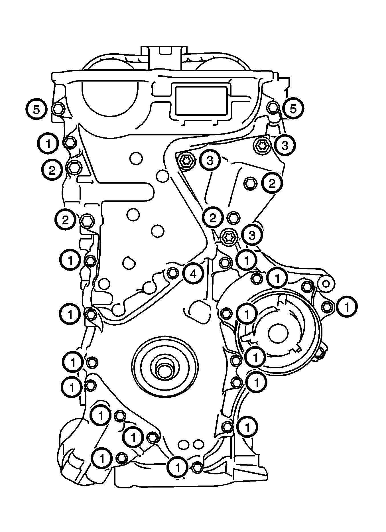
- Fully tighten the timing chain cover sub-assembly with the 26 bolts.
| • | bolts 1 and 5 to
26 N·m (19 lb ft) |
| • | bolts 2 and 3 to
51 N·m(37 lb ft) |
| • | bolt 4 to
10 N·m (7 lb ft) |
- Install the crankshaft pulley.
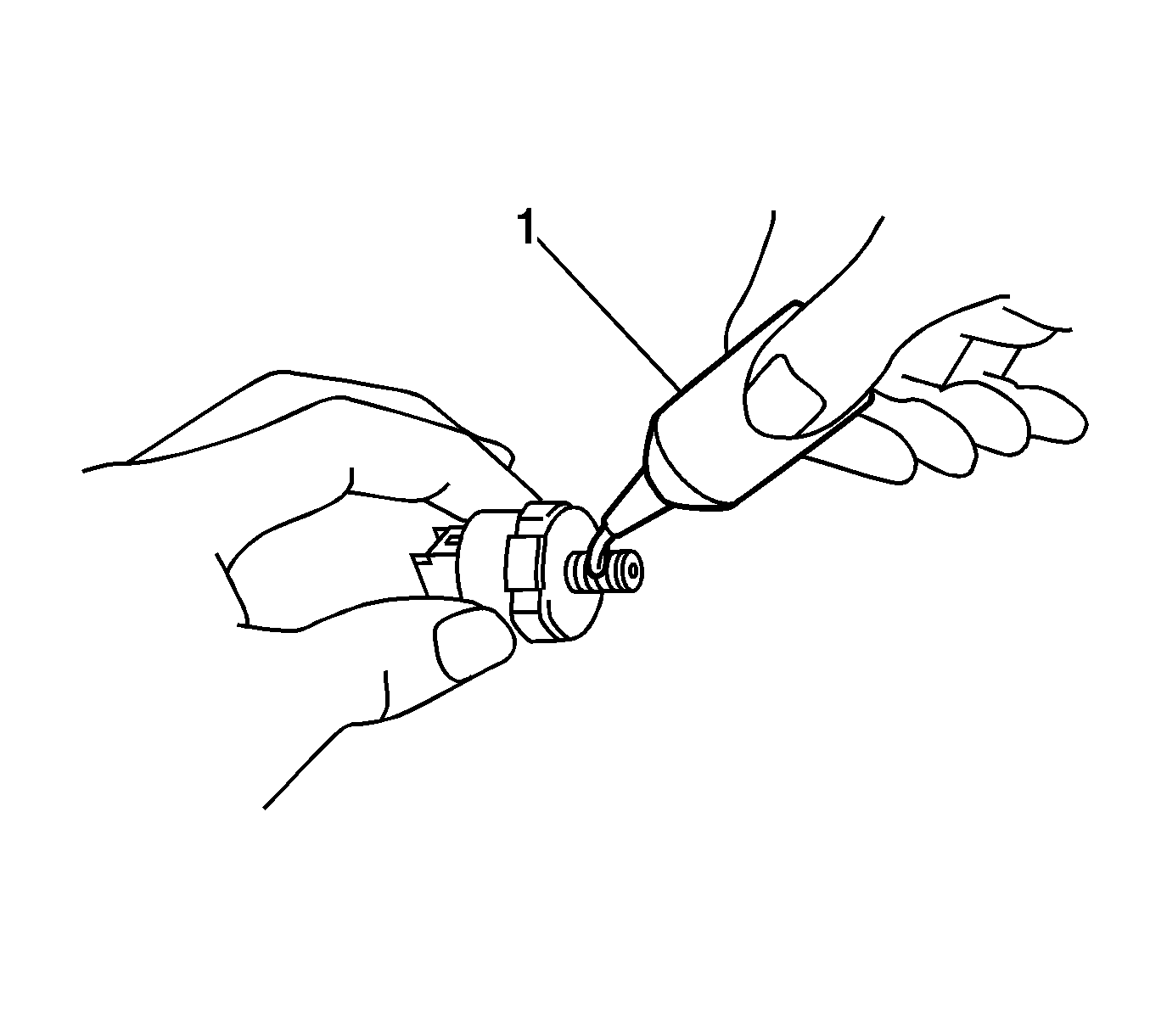
- Install the engine oil pressure switch assembly.
- Apply Three Bond 1344 or equivalent adhesive (1) to 2 or 3 threads of the oil pressure switch.
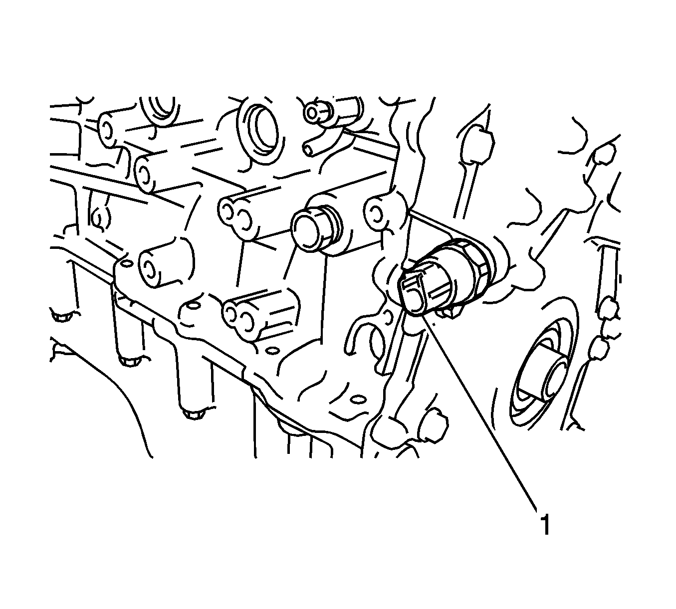
Note:
| • | Install the oil pressure switch within 3 minutes after applying adhesive. |
| • | Do not start the engine within 1 hour after installation. |
- Using a 24 mm deep socket wrench, install the oil pressure switch (1) and tighten to
15 N·m (11 lb ft).
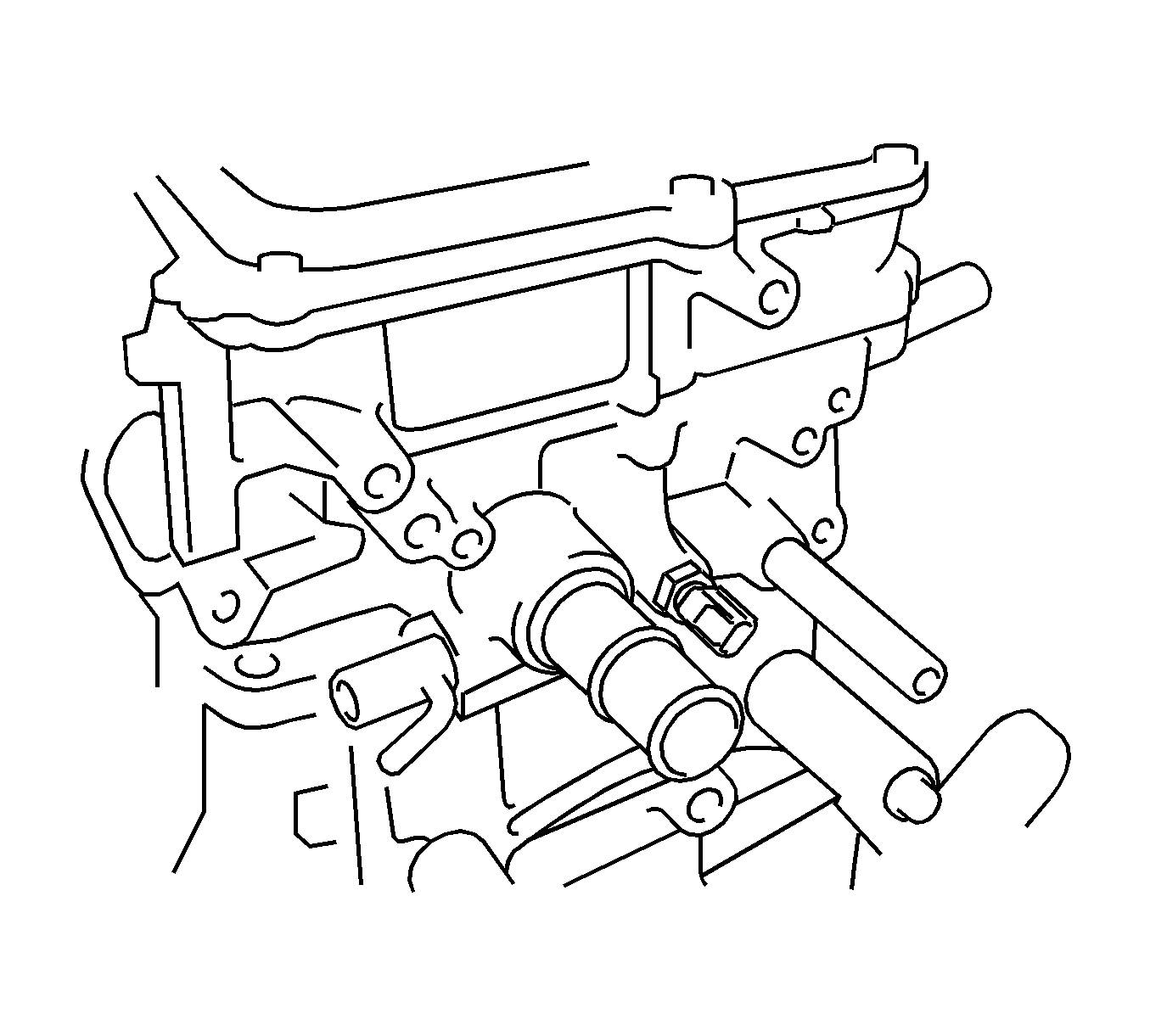
- Install the engine coolant temperature sensor.
- Install a new gasket to the engine coolant temperature sensor.
- Using a 19 mm deep socket wrench, install the temperature sensor and tighten to
20 N·m (15 lb ft).
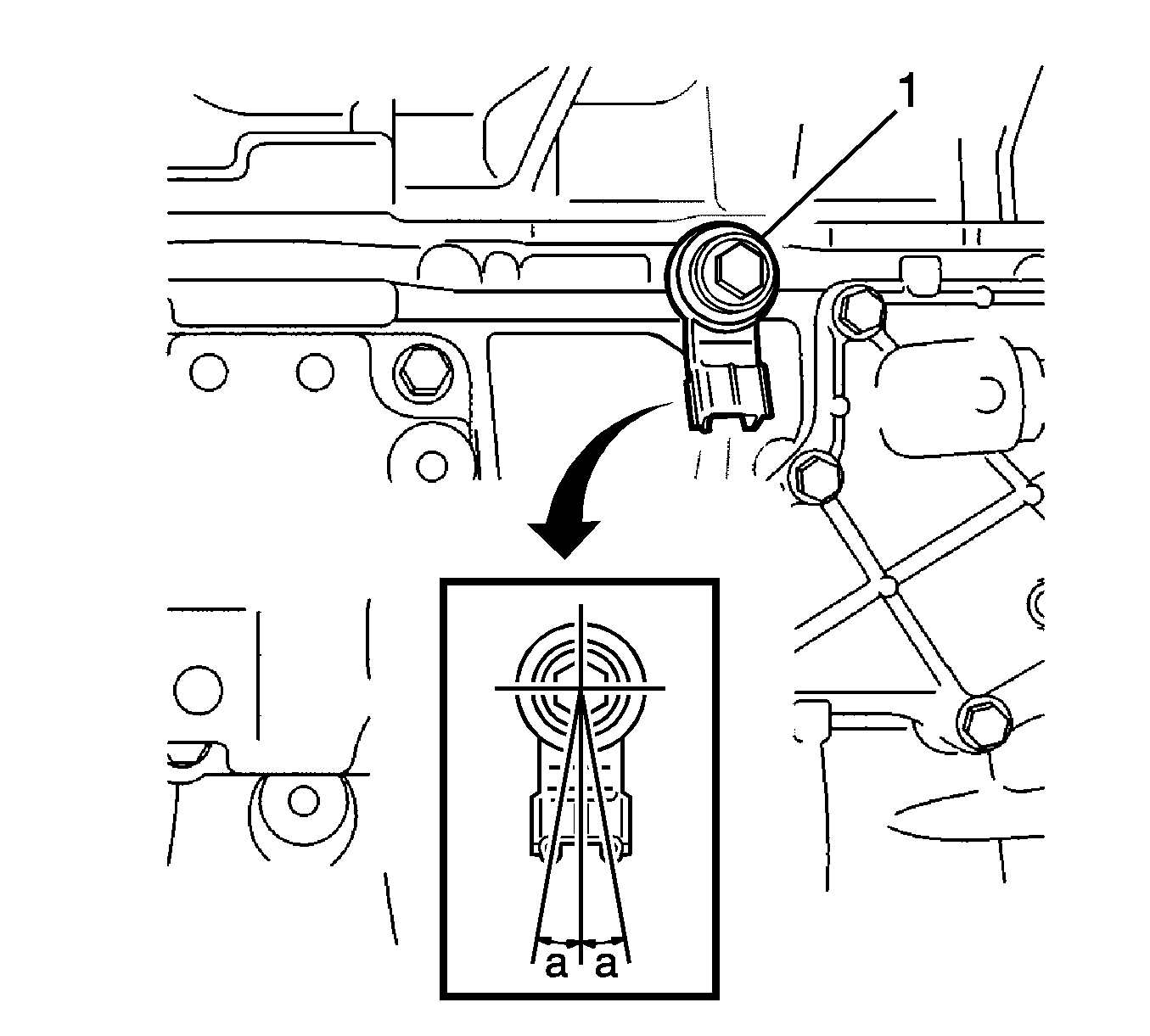
Note: Make sure that the knock control sensor is in the correct position.
- Install the knock control sensor (1) with the bolt and tighten to
21 N·m (16 lb ft).
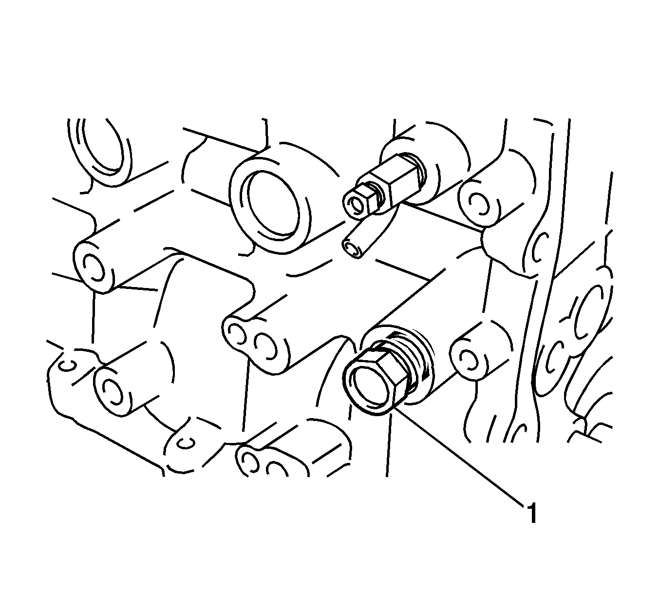
- Install the taper screw plug (1).
Note:
| • | Install the plug within 3 minutes after applying adhesive. |
| • | Do not start the engine within 1 hour after installation. |
- Apply Three Bond 1324 or equivalent adhesive to 2 or 3 threads of the plug, and install the plug and tighten to
43 N·m (32 lb ft).
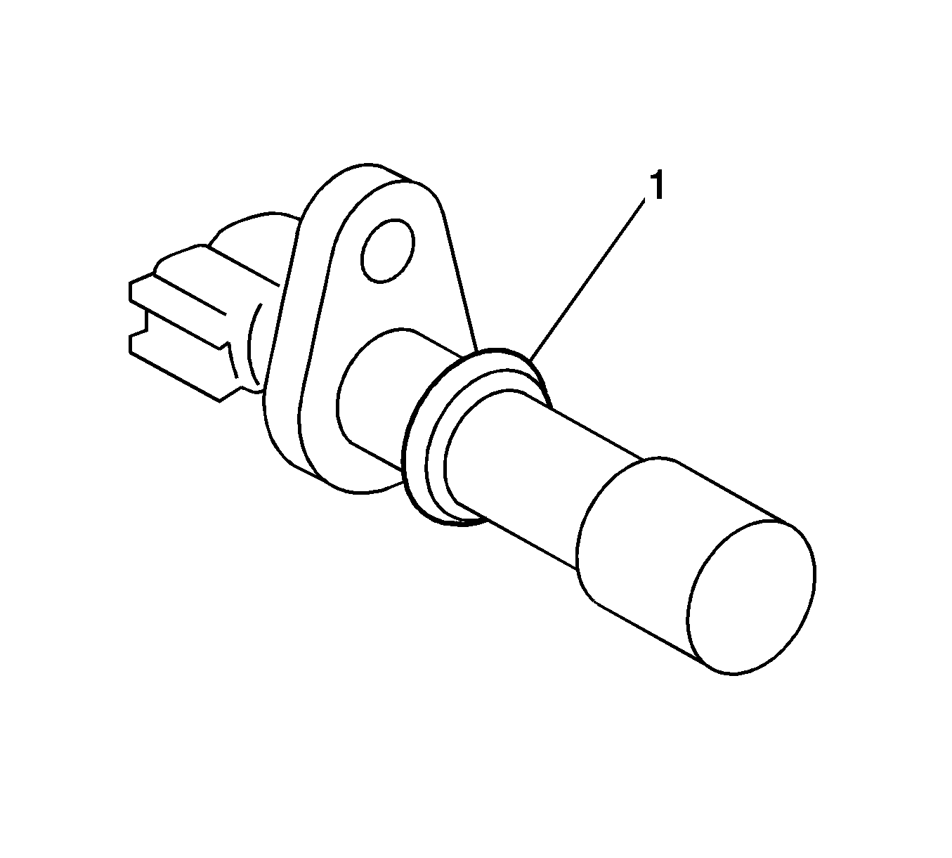
- Install the crankshaft position sensor.
- Apply a light coat of engine oil to the O-ring (1) of the sensor.
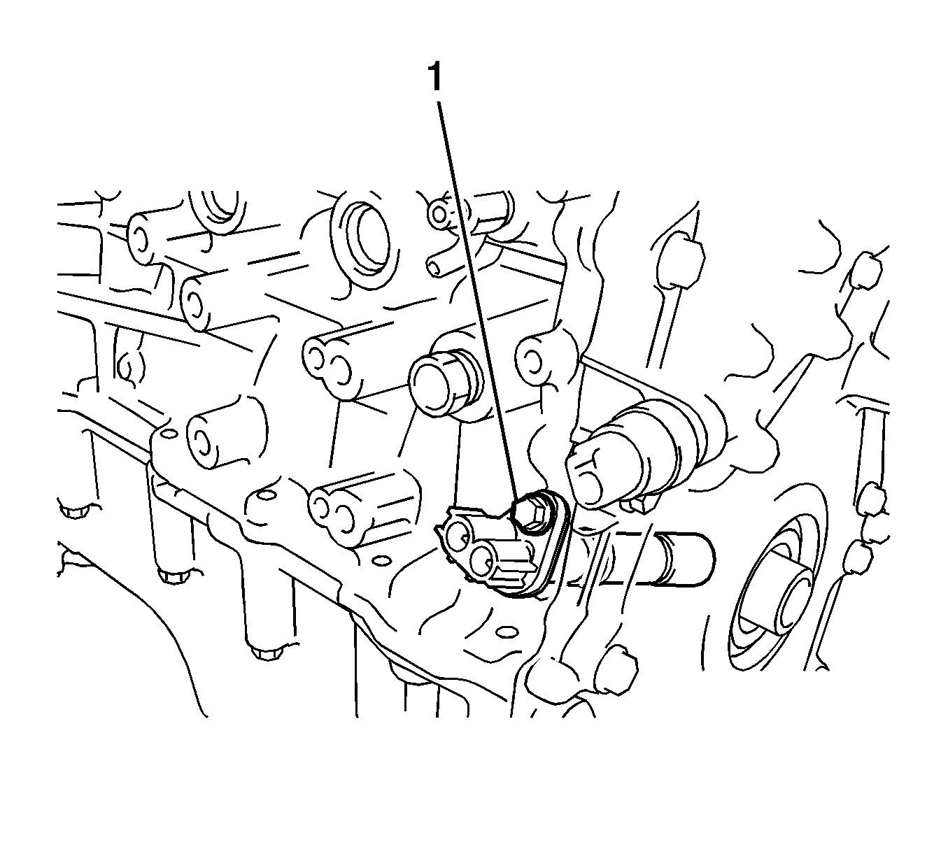
- Install the crankshaft position sensor (1) with the bolt and tighten to
10 N·m (7 lb ft).
- Install the oil filter cap assembly.


