Removal Procedure
- Discharge the fuel system pressure. Refer to Fuel Pressure Relief.
- Align the front wheels facing straight ahead.
- Remove the front wheel.
- Remove the engine under cover LH.
- Remove the engine under cover RH.
- Drain the engine coolant. Refer to Cooling System Draining and Filling.
- Drain the manual transaxle oil for the manual transaxle.
- Drain the automatic transaxle fluid for the automatic transaxle.
- Remove the engine cover.
- Separate the air cleaner filter element from the air cleaner.
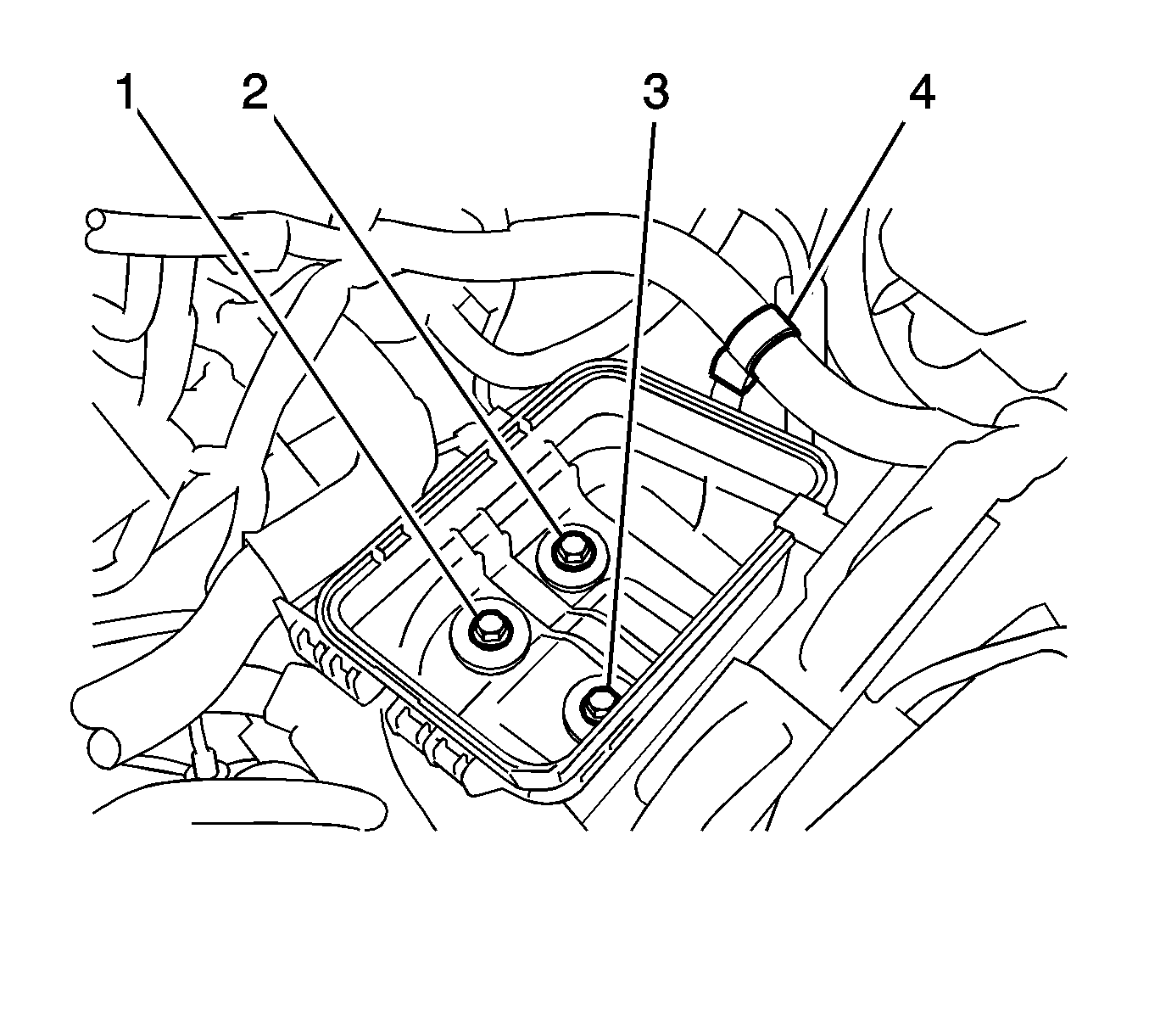
- Disconnect the engine wire harness clamp (4) from air cleaner case.
- Remove the 3 bolts (1-3) and the air cleaner case.
- Remove the battery. Refer to Battery Replacement.
- Remove the battery carrier. Refer to Battery Tray Replacement.
- Separate the 2 wire harness clamps from the battery carrier.
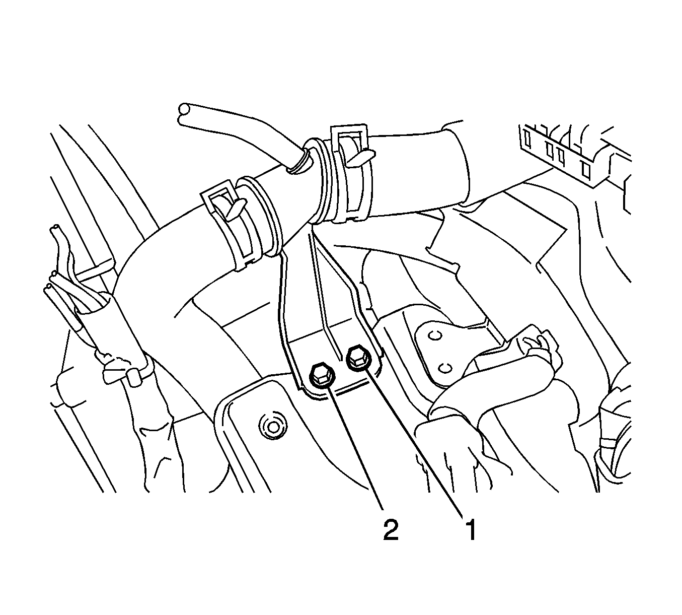
- Remove the 2 bolts (1).
- Separate the radiator pipe from the battery carrier.
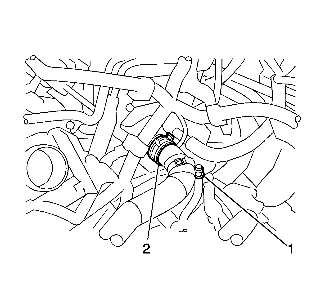
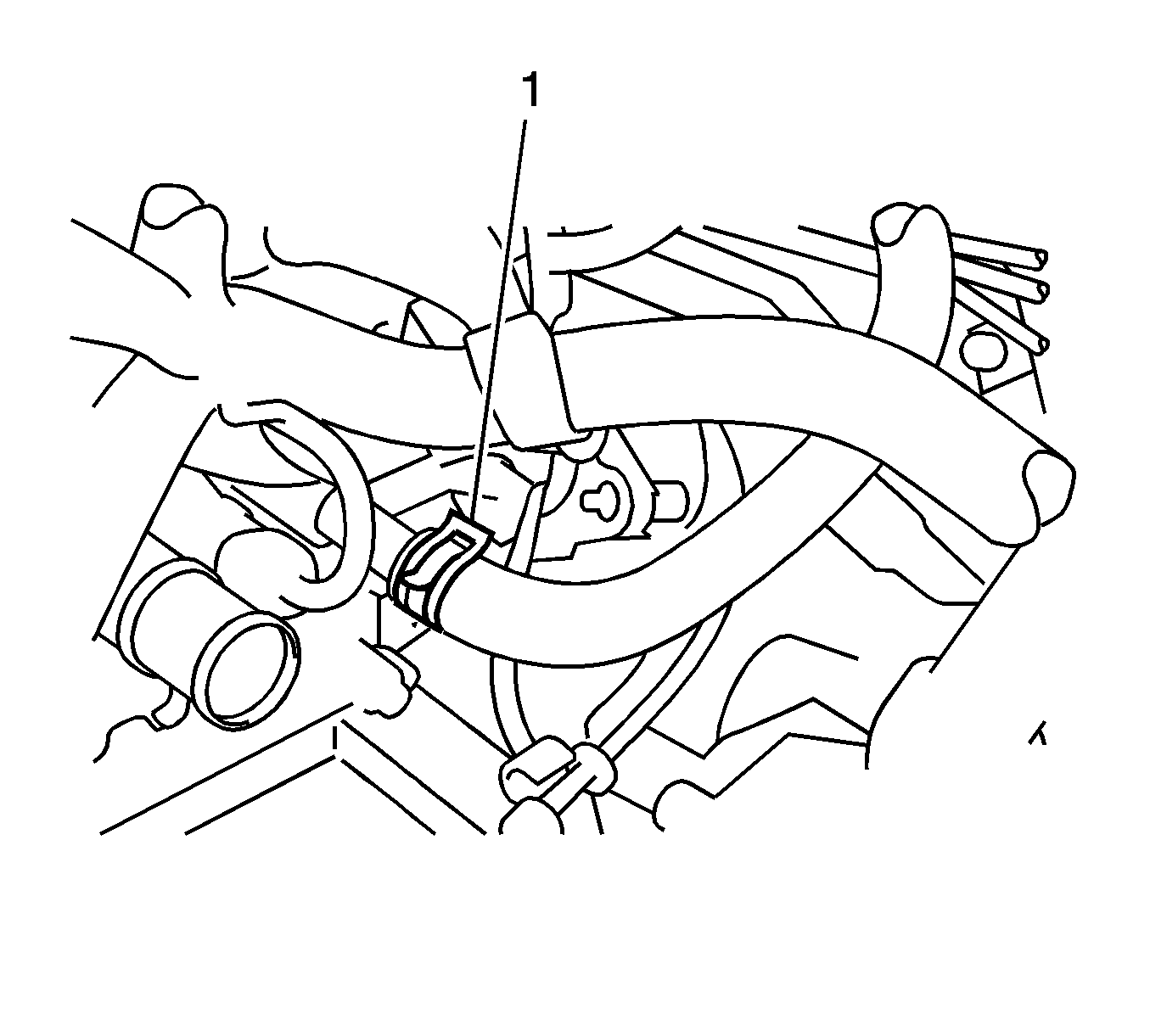
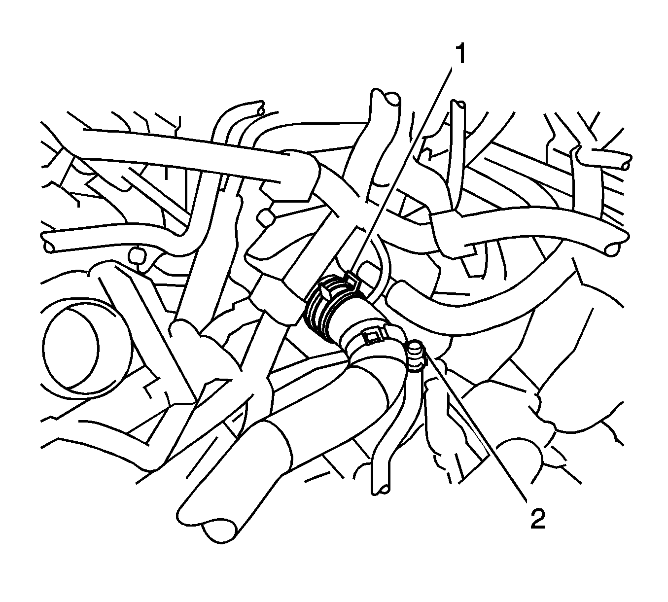
- Disengage the clamp (1) from the upper radiator hose.
- Disconnect the upper radiator hose from the cylinder head.
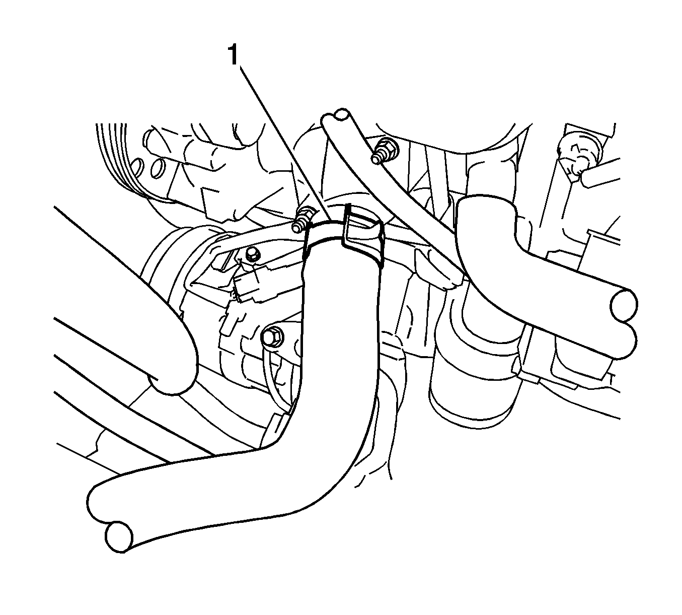
- Disconnect the lower radiator hose (1) from the water inlet.
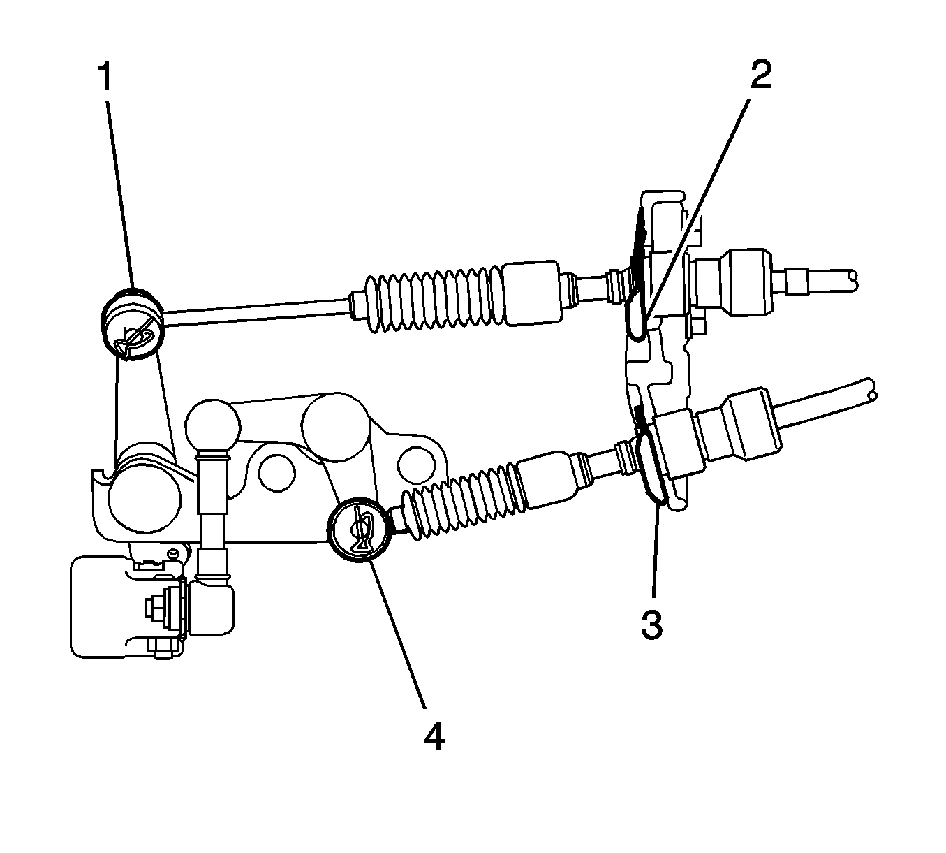
- If equipped with manual transmission, remove the 2 clips (1, 4) and disconnect the 2 cables (2, 3) from the transaxle.
- If equipped with automatic transmission, disconnect the control cable from the control cable support.
- Remove the nut and disconnect the control cable from the control shaft lever.
- Remove the clip (1) and disconnect the control cable from the control cable bracket.
- Remove the bolt and disconnect the clamp of the control cable.
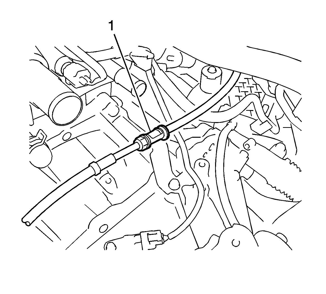
- Disconnect the fuel vapor feed hose assembly (1).
- Disconnect the union to connector tube hose (1).
- Disconnect the 2 oil cooler hoses (1, 2) from the oil cooler tube, if equipped with automatic transaxle.
- Disconnect the outlet heater water hose (1) from the engine.
- Disconnect the inlet heater water hose (1) from the engine.
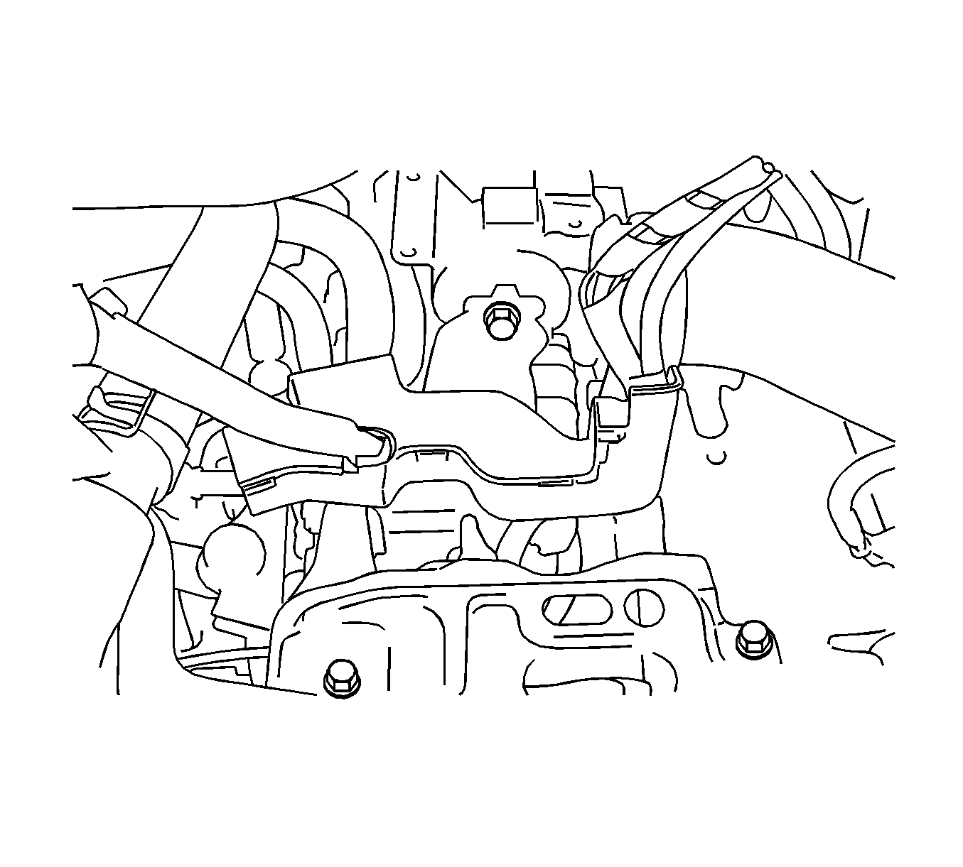
- Release the claw and remove the fuel pipe clamp (1).
- Pinch the retainer (1) then pull the fuel tube connector out of the pipe.
- Remove the V-ribbed belt.
- Remove the generator assembly.
- Separate the compressor with pulley assembly with air conditioning system.
- Disconnect the connector.
- Remove the 2 bolts and 2 nuts.
- Using a TORX socket wrench, remove the 2 stud bolts and compressor with pulley assembly.
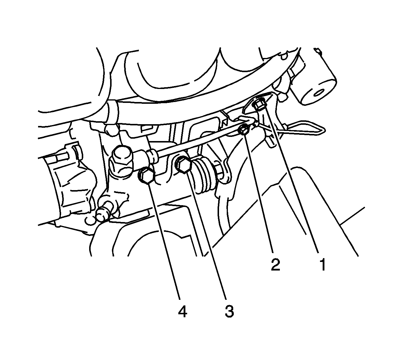
- Remove the 4 bolts (1-4) and clutch tube bracket, and separate the clutch release cylinder assembly.
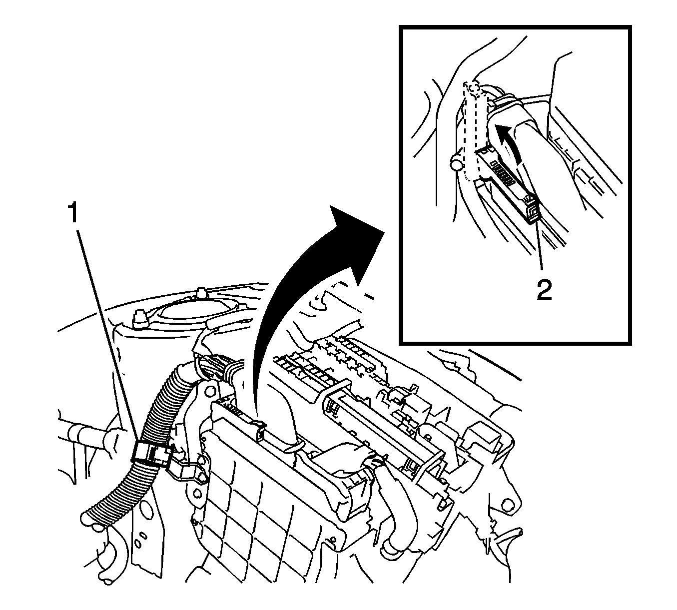
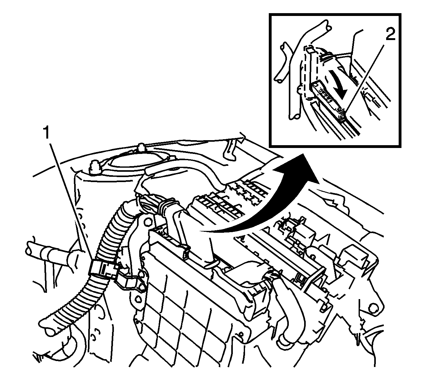
- Disconnect the wire harness from the clamp (1).
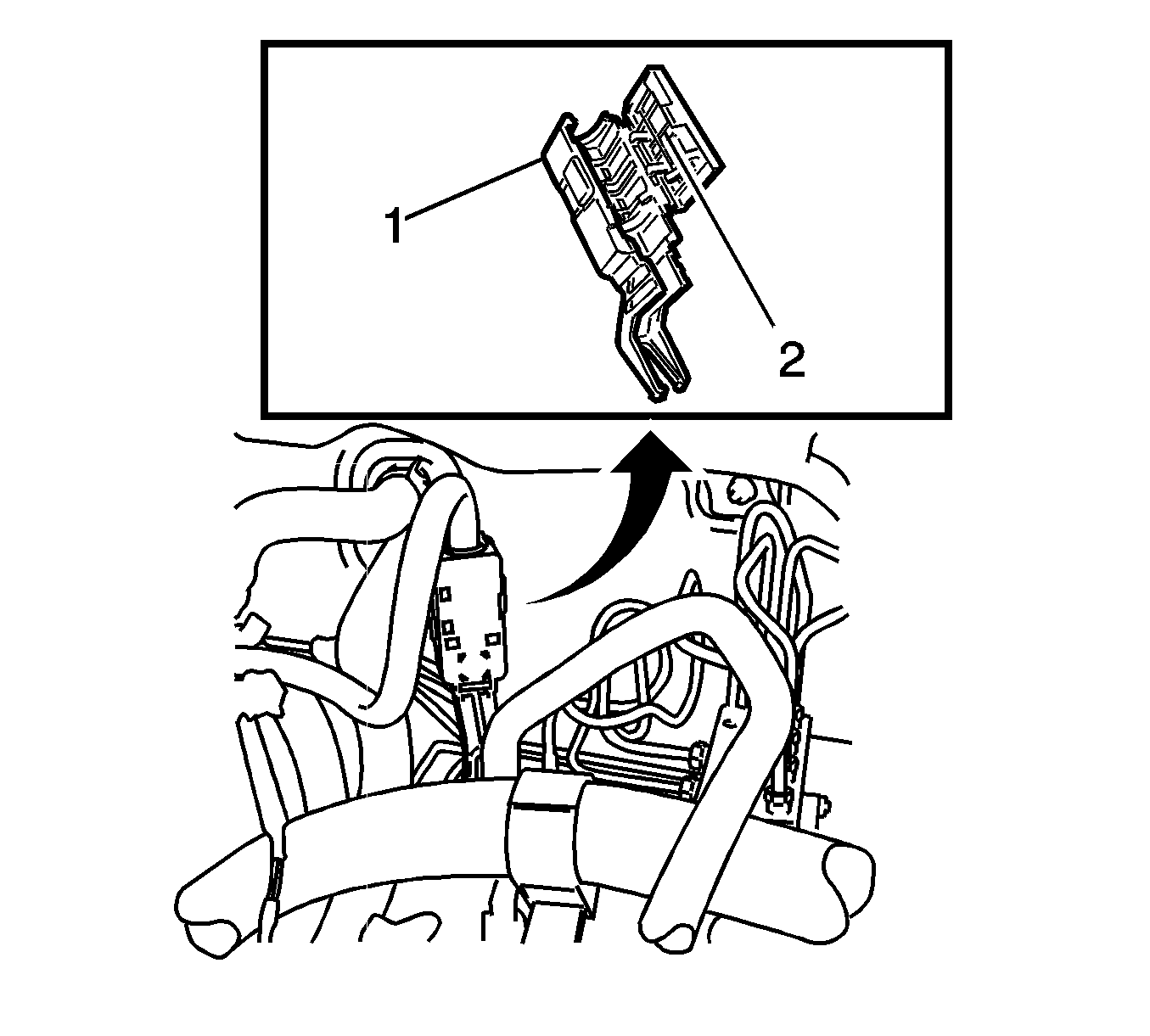
- Pull up the lever (2) and disconnect the ECM connector.
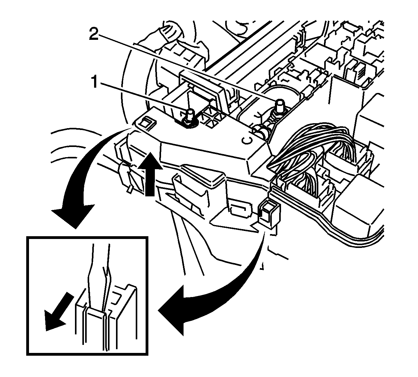
- Remove the 2 nuts (1, 2).
- Remove the 3 connectors and 2 clamps from the engine room junction block and disconnect the wire harness.
- Remove the bolt (2) and clamp (1) for the manual transaxle.
- Remove the bolt (1) and clamp (2) for the automatic transaxle.
- Remove the ground cable on the right side of the cylinder head.
- Secure the steering wheel.
- Remove the column hole cover silencer sheet.
- Separate the steering intermediate shaft assembly.
- Disconnect the steering column hole cover sub-assembly.
- Remove the front exhaust pipe assembly. Refer to Front Pipe Replacement.
- Remove the front axle shaft LH nut.
- Remove the front axle shaft RH nut.
- Disconnect the front speed sensor LH.
- Disconnect the front speed sensor RH.
- Separate the tie rod end assembly LH.
- Separate the tie rod end assembly RH.
- Separate the front stabilizer link assembly LH.
- Separate the front stabilizer link assembly RH.
- Separate the front lower suspension arm assembly LH.
- Separate the front lower suspension arm assembly RH.
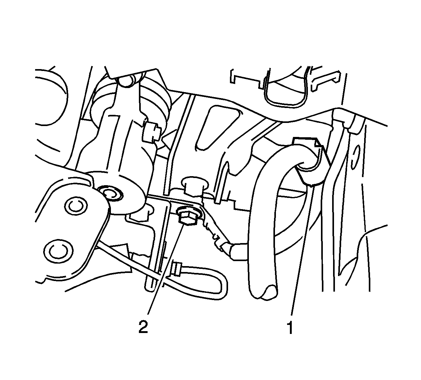
- Separate the steering knuckle from the axle hub LH.
- Separate the steering knuckle from the axle hub RH.
- Remove the flywheel housing under cover--for automatic transaxle.
- Remove the drive plate and torque converter clutch setting bolt--for automatic transaxle.
- Remove the front suspension crossmember assembly. Refer to Front Suspension Crossmember Replacement.
- Remove the engine assembly with transaxle.
- Set the engine lifter.
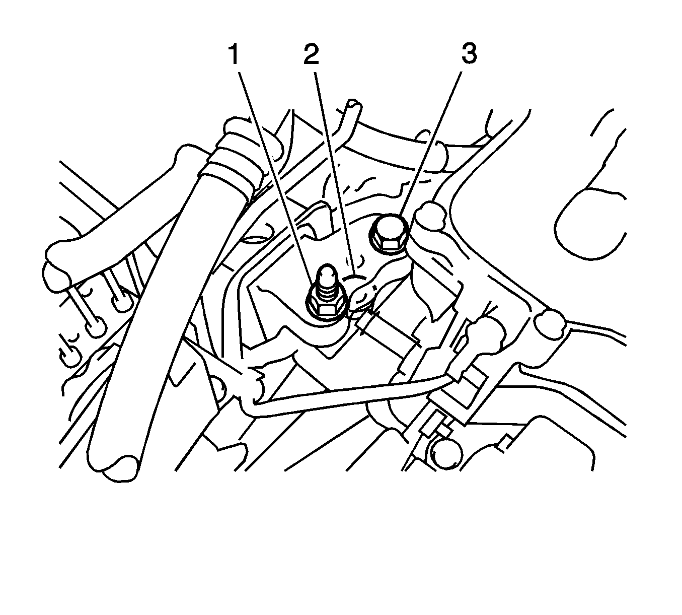
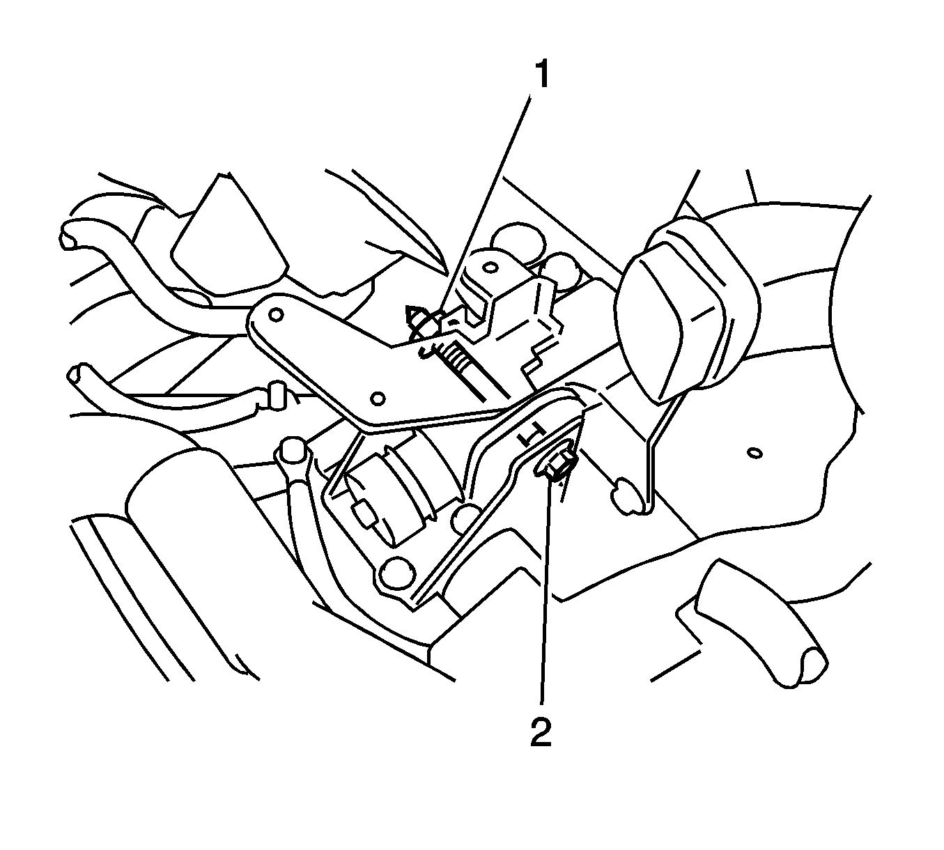
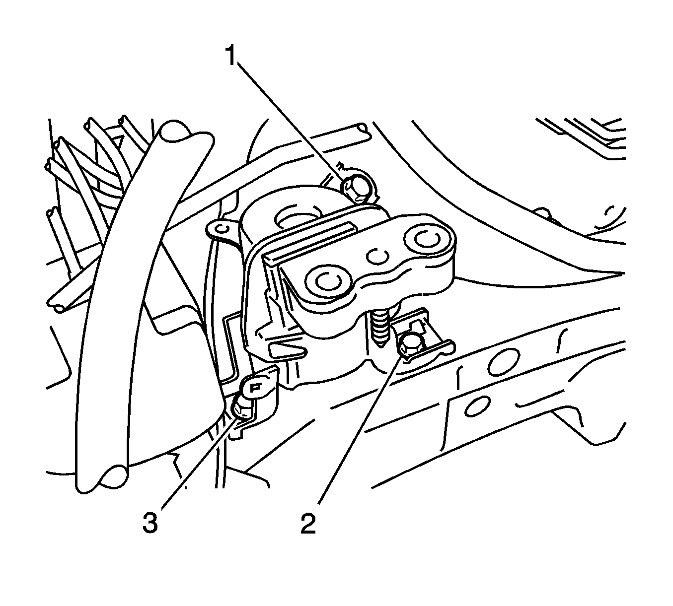
- Remove the bolt (1) and 2 nuts (2, 3), and separate the engine mount RH.
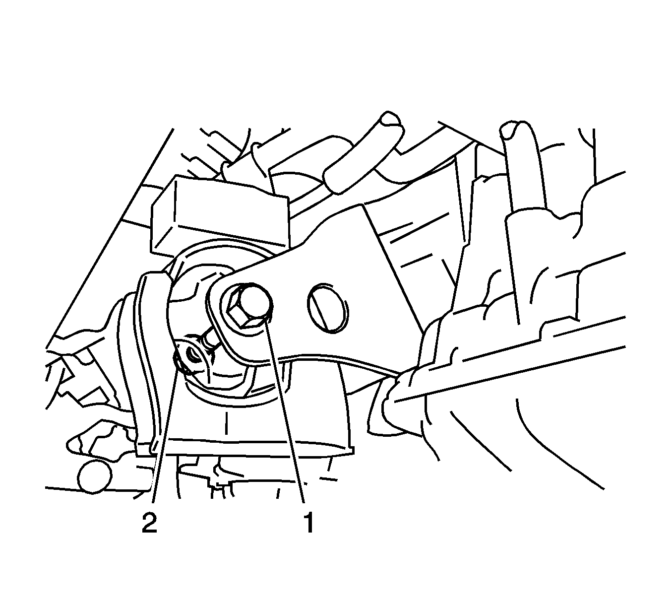
- Remove the through bolt (1) and nut (2), and separate the engine mount LH.
- Carefully remove the engine with transaxle from the vehicle.
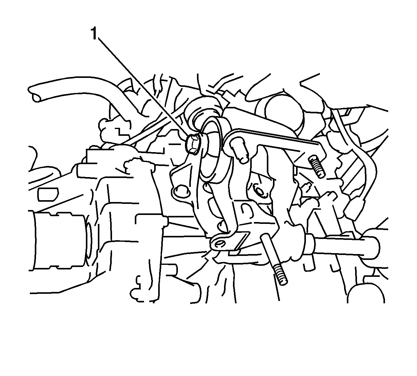
- Remove the bolt (1) and nut (2), and remove the front engine mount.
- Remove the through bolt (1) and the rear engine mount.
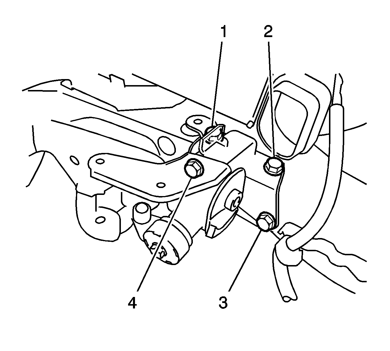
- Remove the 4 bolts (1-4) and engine mount LH.
- Remove the engine mount RH.
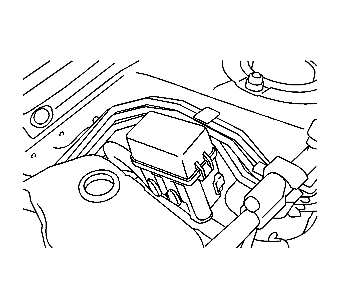
- Disconnect the clamp, and release the relay block assembly.
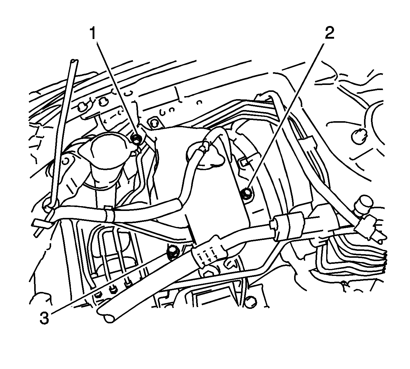
- Remove the 3 bolts (1-3) and radiator reserve tank.
- Remove the 3 bolts (1-3) and engine mount RH.
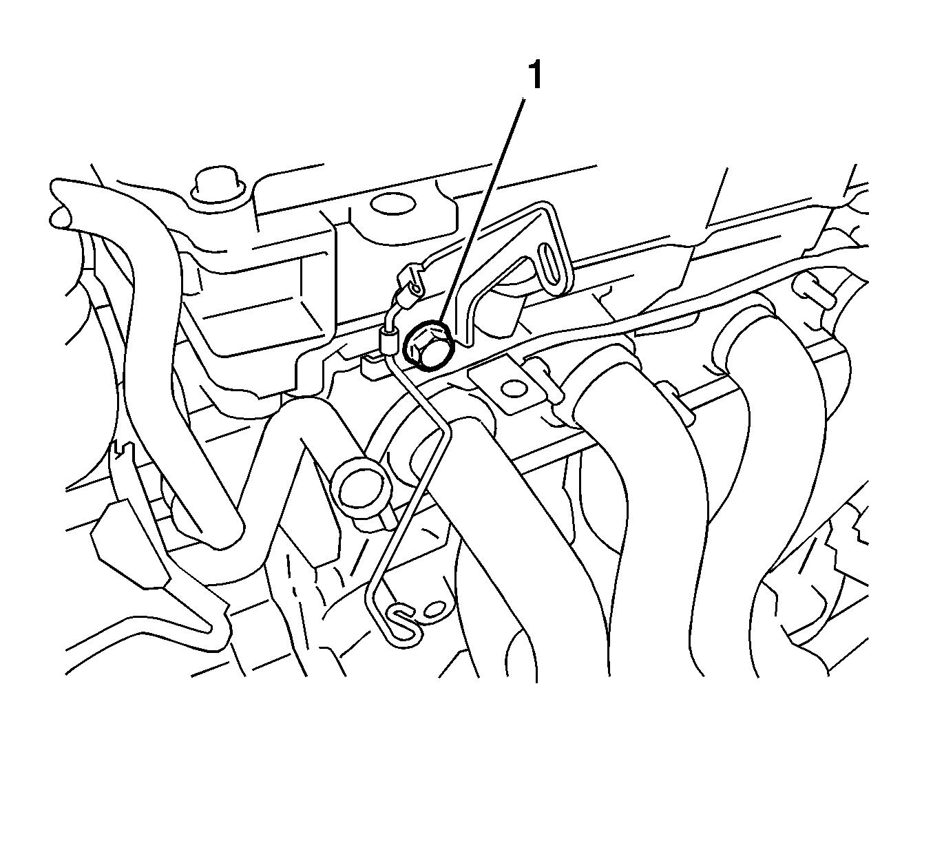
- Remove the bolt (1) and wire harness bracket.
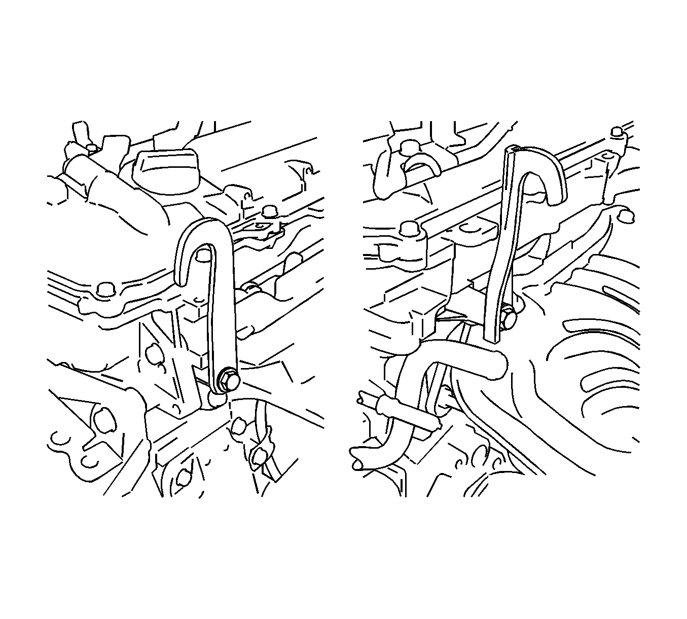
- Install the 2 engine hangers with the 2 bolts and tighten to 43 N·m (32 lb ft).
- Remove the flywheel housing side cover.
- Remove the starter assembly.
- Remove the transaxle assembly.
- Remove the clutch cover assembly for the manual transaxle.
- Remove the clutch disc assembly for the manual transaxle.
- Remove the flywheel assembly for the manual transaxle.
- Remove the drive plate and ring gear assembly for the automatic transaxle.
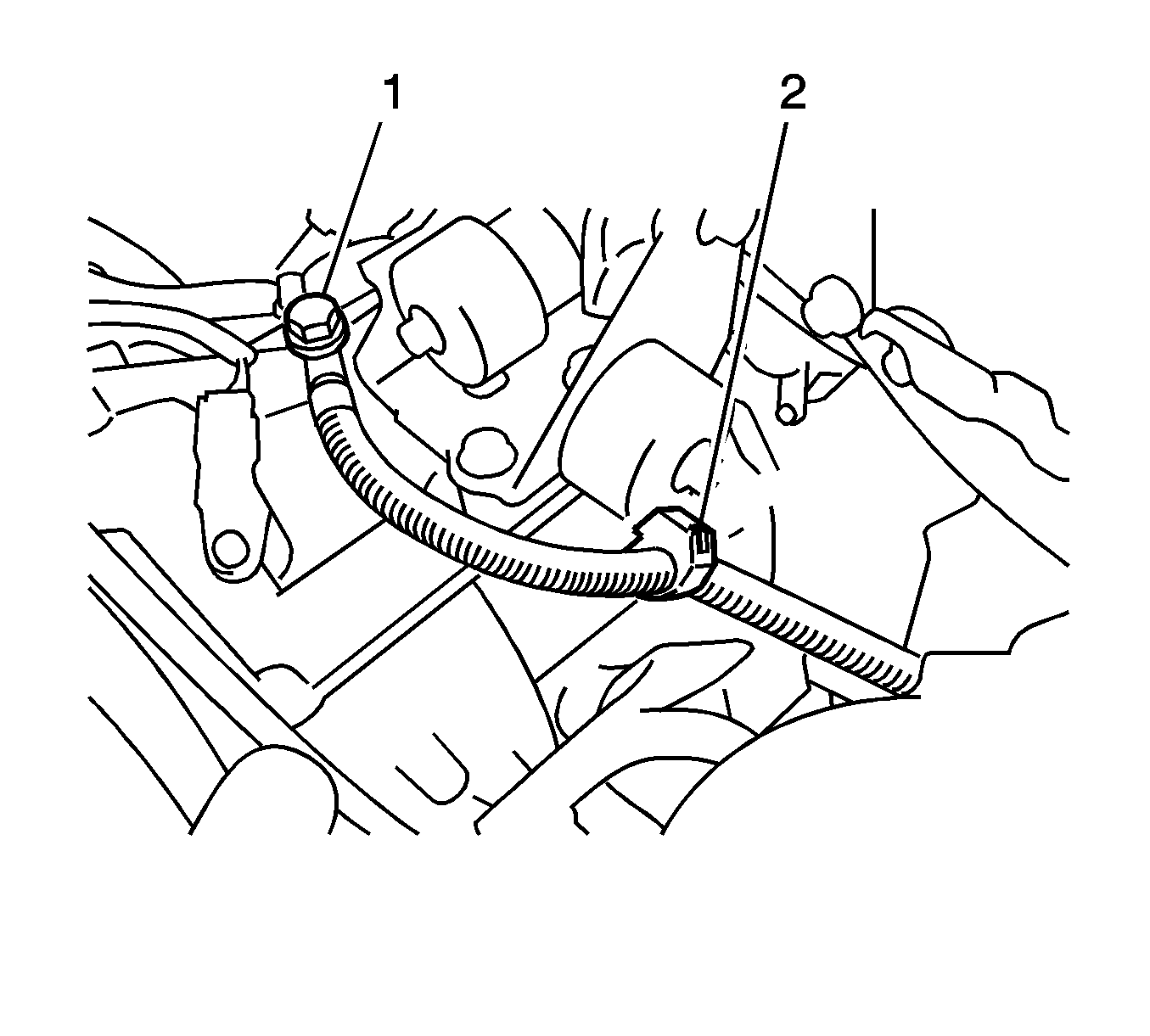
- Remove the engine wire harness.
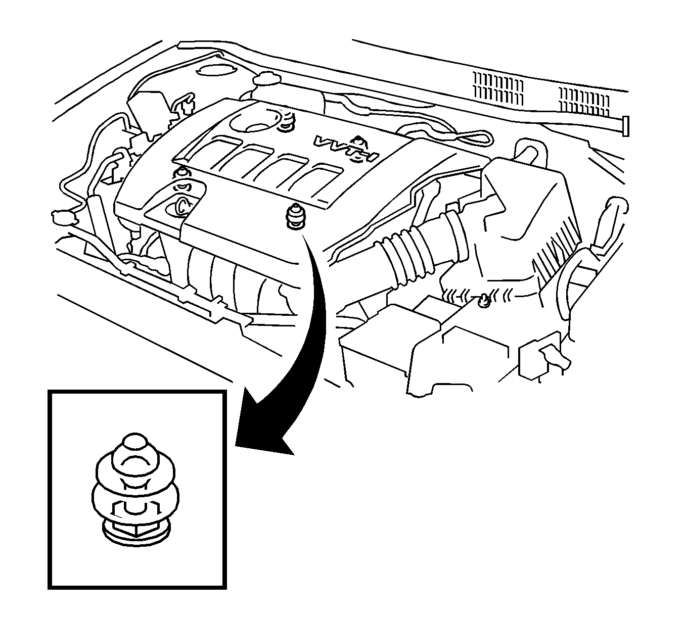
Note: Attempting to disengage both front and rear clips at the same time may cause the cover to break.
Hold the rear of the cover and raise it to disengage the 2 clips on the rear of the cover. Continue to raise the cover to disengage the 2 clips on the front of the cover and remove the cover.
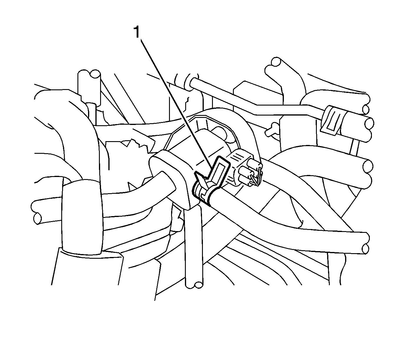
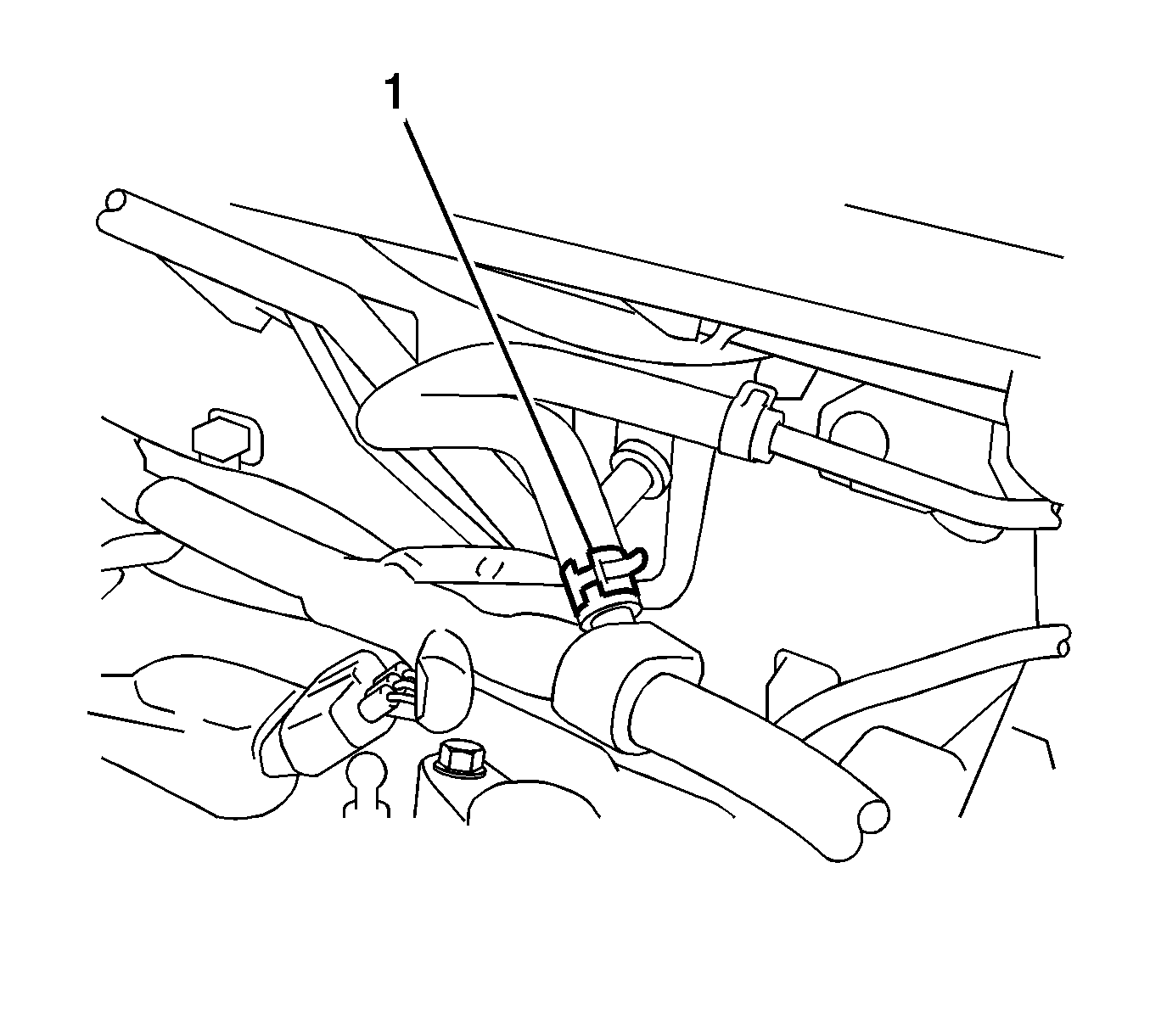
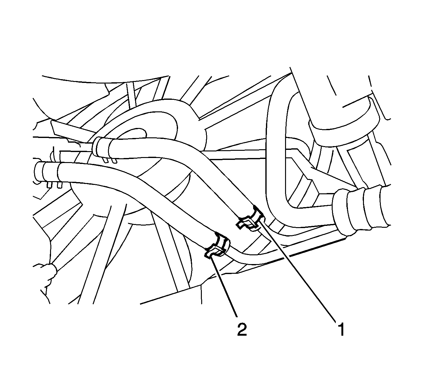
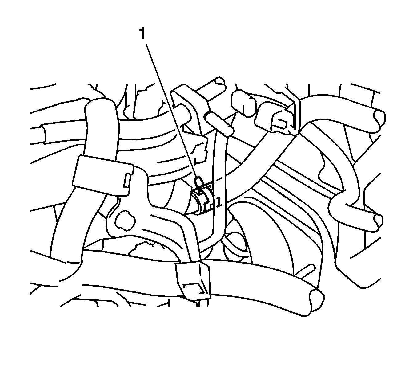
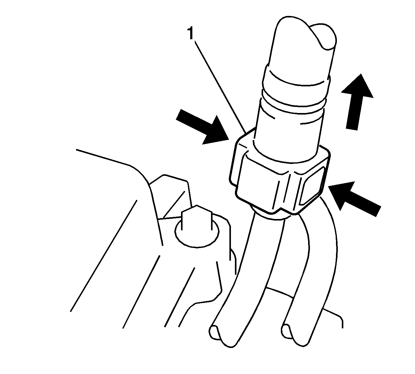
Note:
• Remove any dirt and foreign matter from the fuel tube connector before performing this work. • Do not allow any scratches or foreign matter on the parts when disconnecting, as the fuel tube connector has the O-rings that seal the pipe. Perform this work by hand. Do not use any tools. • Do not forcibly bend, kink or twist the nylon tube. • Protect the disconnected parts by covering them with vinyl bags after disconnecting the fuel tube. • If the fuel tube connector and pipe are stuck, push and pull to release them.
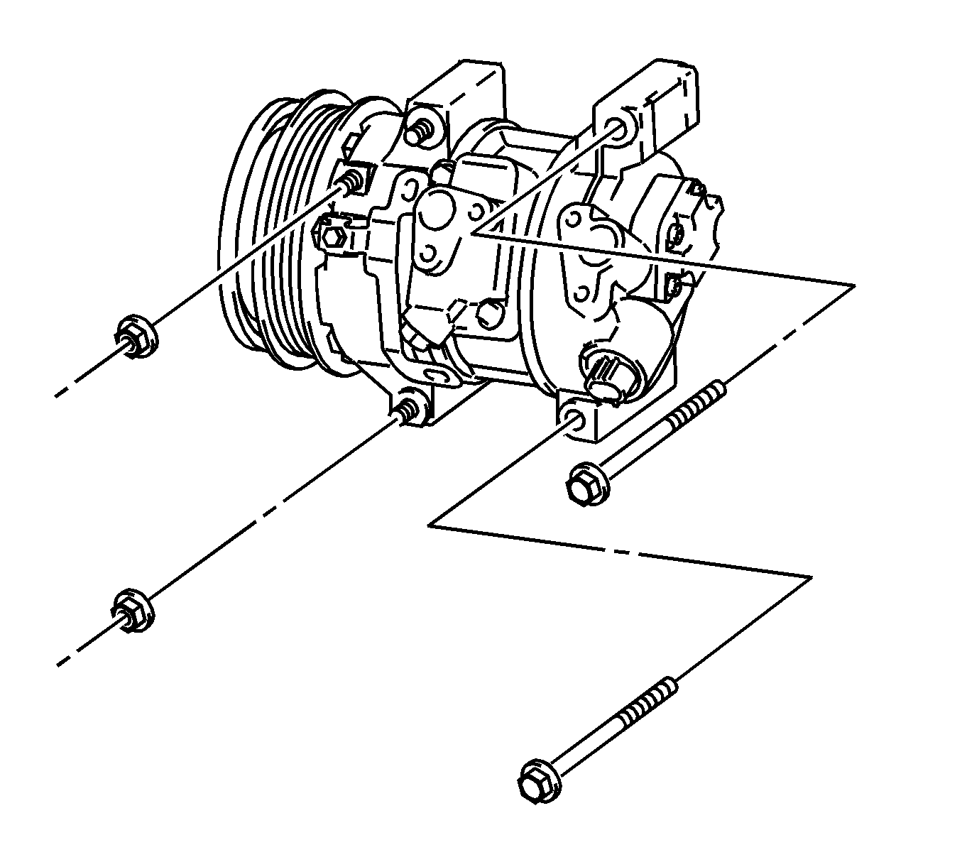
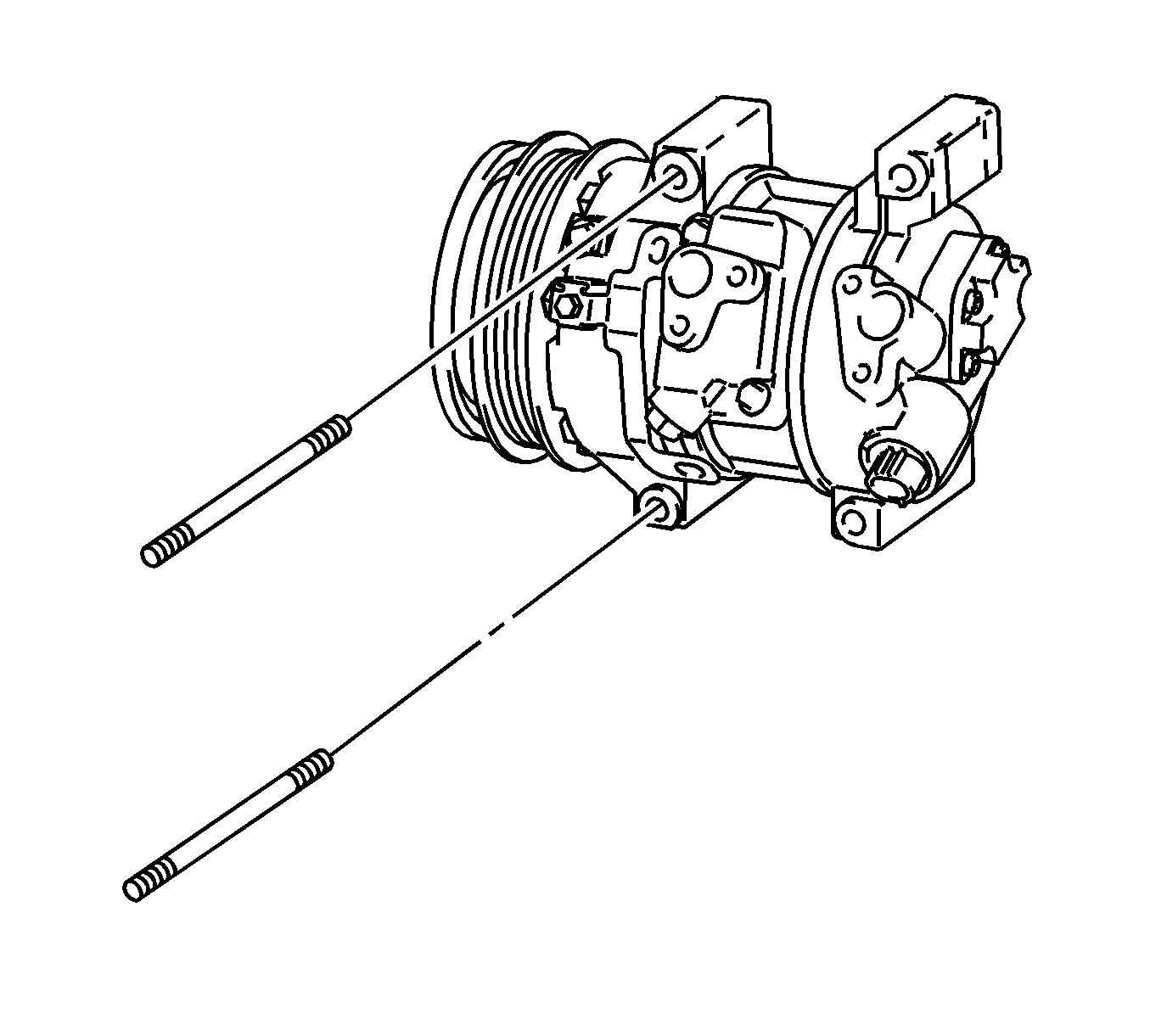
Note: Secure the compressor and hoses off to the side instead of discharging the A/C system.
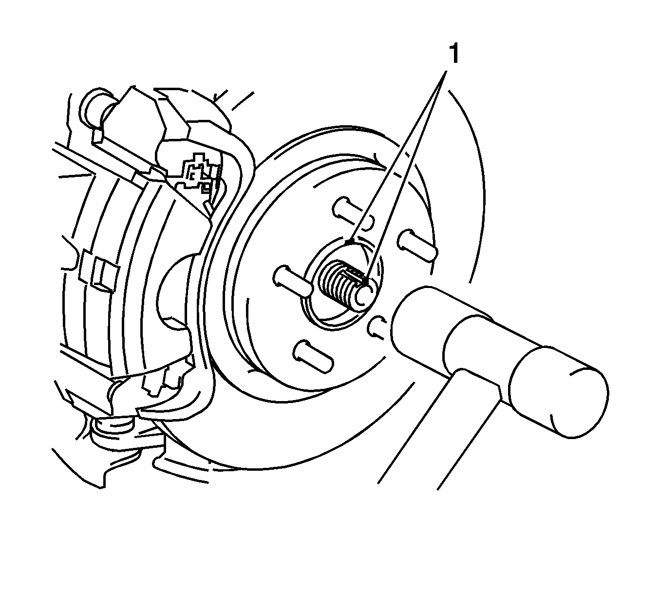
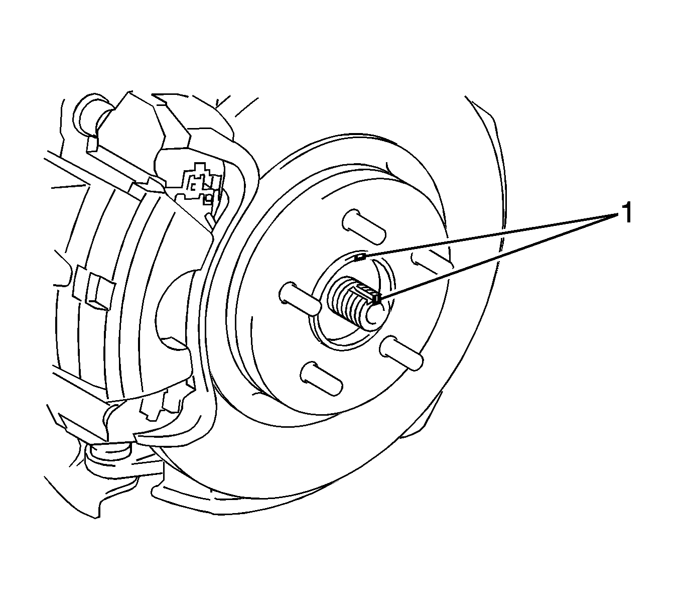
| 62.1. | Put matchmarks on the drive shaft and axle hub. |
| 62.2. | Using a plastic-faced hammer, disconnect the front axle assembly LH. |
Note: Place the engine on wooden blocks or equivalent so that the engine is level.
Note: Perform this procedure only when replacement of the engine mounting insulator is necessary.
Note: Perform this procedure only when replacement of the engine mounting insulator is necessary.
Installation Procedure
- Install the engine wire harness.
- Install the flywheel assembly for the manual transaxle.
- Install the drive plate and ring gear assembly for the automatic transaxle.
- Install the clutch disc assembly for the manual transaxle.
- Install the clutch cover assembly for the manual transaxle.
- Inspect and adjust clutch cover assembly for the manual transaxle.
- Install the transaxle assembly.
- Install the starter assembly.
- Install the flywheel housing side cover.
- Install the front engine mount with the nut (2) and bolt (1) and tighten to 73 N·m (54 lb ft).
- Install the rear engine mount to the engine mounting bracket with the through bolt (1) and tighten to 65 N·m (50 lb ft).
- Temporarily install the engine mount LH with the 4 bolts (1-4).
- Install the 4 bolts and tighten to 52 N·m (38 lb ft).
- Install the engine mount RH with the 3 bolts (1-3) and tighten to 52 N·m (38 lb ft).
- Install the radiator reserve tank with the 3 bolts (1-3) and tighten to 7.0 N·m (62 lb in).
- Install the relay block assembly.
- Set the engine assembly with transaxle and front suspension crossmember on the engine lifter.
- Operate the engine lifter and lift the engine assembly with transaxle and front suspension crossmember to the position where the engine mounts RH and LH can be installed.
- Install the engine mount LH with the through bolt (2) and nut (1) and tighten to 56 N·m (41 lb ft).
- Install the engine mount RH with the bolt (1) and 2 nuts (2, 3) and tighten.
- Install the front suspension crossmember assembly. Refer to Front Suspension Crossmember Replacement.
- Remove the 2 engine hangers with the 2 bolts.
- Install the wire harness bracket with the bolt (1) and tighten to 60 N·m (44 lb ft).
- Install the drive plate and torque converter clutch setting bolt for the automatic transaxle.
- Install the flywheel housing under cover for the automatic transaxle.
- Install the steering knuckle with axle hub LH by aligning the matchmarks and connect the front drive shaft assembly to the front axle assembly LH.
- Install the steering knuckle with axle hub RH.
- Install the front lower suspension arm assembly LH.
- Install the front lower suspension arm assembly RH.
- Install the front stabilizer link assembly LH.
- Install the front stabilizer link assembly RH.
- Connect the tie rod end assembly LH.
- Connect the tie rod end assembly RH.
- Install the front speed sensor LH.
- Install the front speed sensor RH.
- Install the front axle shaft LH nut.
- Install the front axle shaft RH nut.
- Install the front exhaust pipe assembly. Refer to Front Pipe Replacement.
- Install the steering column hole cover sub-assembly.
- Install the steering intermediate shaft assembly.
- Install the column hole cover silencer sheet.
- Install the ground wire to the engine compartment wire with the bolt (2) and clamp (1) for the manual transaxle and tighten to 13 N·m (10 lb ft).
- Install the ground wire to the engine compartment wire with the bolt (1) and clamp (2) for the automatic transaxle and tighten to 26 N·m (19 lb ft).
- Install the wire harness with the 2 nuts (2, 3) and tighten to 8.4 N·m (74 lb in).
- Connect the 3 connectors and wire harness clamp to the engine room junction block.
- Connect the connector to the ECM with the clamp (1) and lock lever (2).
- Install the clutch release cylinder assembly with the 5 bolts (1-3) and clutch tube bracket for the manual transaxle and tighten.
- Install the compressor with pulley assembly with air conditioning system.
- Install the generator assembly. Refer to Generator Replacement.
- Install the V-ribbed belt. Refer to Drive Belt Replacement.
- Connect the fuel tube connector and fuel pipe.
- Engage the claw (2) and install the fuel pipe clamp (1).
- Connect the inlet heater water hose with the clamp (1).
- Connect the outlet heater water hose with the clamp (1).
- Connect the union to check valve hose with the clamp.
- Connect the 2 oil cooler hoses with the clamps (1, 2)--for automatic transaxle.
- Connect the union to connector tube hose (1).
- Connect the fuel vapor feed hose (1) assembly.
- Install the transmission control cables (2, 3) to the control cable bracket with 2 new clips (1, 4)--for manual transaxle.
- If equipped with automatic transmission secure the control cable onto the control cable bracket (1) with the clip.
- Connect the control cable onto the control shaft lever with the nut and tighten to 12 N·m (9 lb ft).
- Connect the control cable to the cable support.
- Connect the clamp of the control cable with the bolt and tighten to 12 N·m (9 lb ft).
- Connect the radiator hose with the clamp (1).
- Connect the radiator hose with the clamp (1).
- Install the battery carrier with the 4 bolts and tighten to 19 N·m (14 lb ft).
- Connect the radiator pipe with the 2 bolts (1, 2) and tighten to 8.8 N·m (78 lb in).
- Connect the 2 wire harness clamps.
- Install the battery clamp with the bolt and nut and tighten.
- Connect the battery cables and tighten to 5.4 N·m (48 lb in).
- Install the air cleaner case with the 3 bolts (1-3) and tighten to 7.0 N·m (62 lb in).
- Install the wire harness clamp (4) to the air cleaner case.
- Add transaxle oil for the manual transaxle.
- Add automatic transaxle fluid for the automatic transaxle.
- Inspect transaxle fluid level for the automatic transaxle.
- Inspect for automatic transaxle fluid leak for the automatic transaxle.
- Inspect the shift lever position for the automatic transaxle.
- Adjust the shift lever position for the automatic transaxle.
- Add the engine coolant. Refer to Cooling System Draining and Filling.
- Add the engine oil.
- Inspect the engine oil level.
- Inspect the for fuel leak.
- Inspect the for engine coolant leak.
- Inspect the for oil leak.
- Inspect the for exhaust gas leak.
- Install the engine under cover LH.
- Install the engine under cover RH.
- Install the front wheels and tighten the nuts to 103 N·m (76 lb ft).
- Inspect the ignition timing.
- Inspect the engine idle speed.
- Adjust the front wheel alignment. Refer to Wheel Alignment Measurement.
- Engage the 4 clips to install the No. 2 cylinder head cover.
- Check the ABS speed sensor signal.
Caution: Refer to Fastener Caution in the Preface section.


Note: Perform this procedure only when replacement of the engine mounting insulator is necessary.


Note: Perform this procedure only when replacement of the engine mount is necessary.
Note: Do not raise the engine more than necessary. If the engine is raised excessively, the vehicle may also be lifted up.
Note:
• Make sure that the engine is clear of all wiring and hoses. • While raising the engine into the vehicle, do not allow it to contact the vehicle.

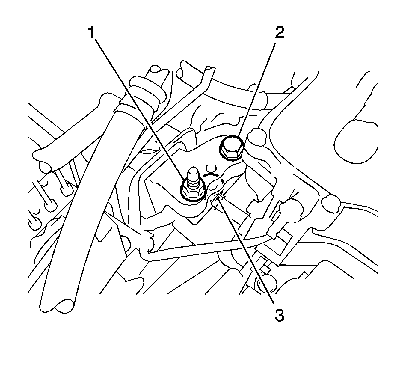
| • | nut 2 to 95 N·m (70 lb ft) |
| • | nut 3 to 52 N·m (38 lb ft) |
| • | bolt to 95 N·m (70 lb ft) |



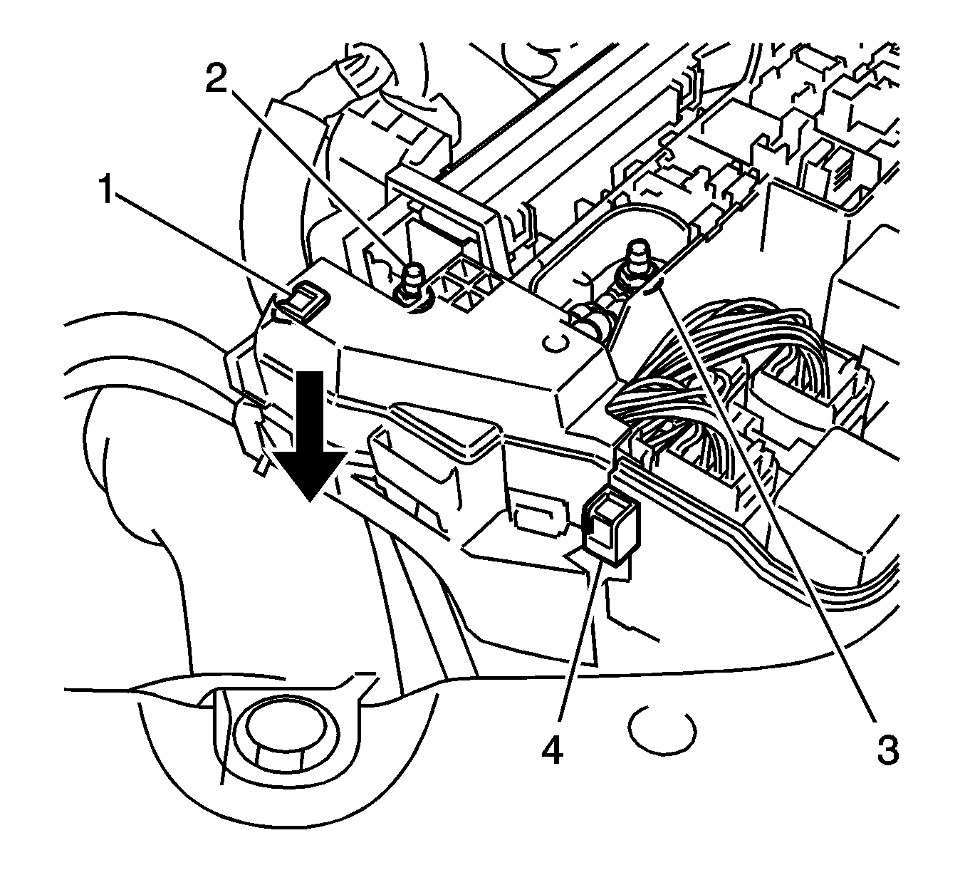
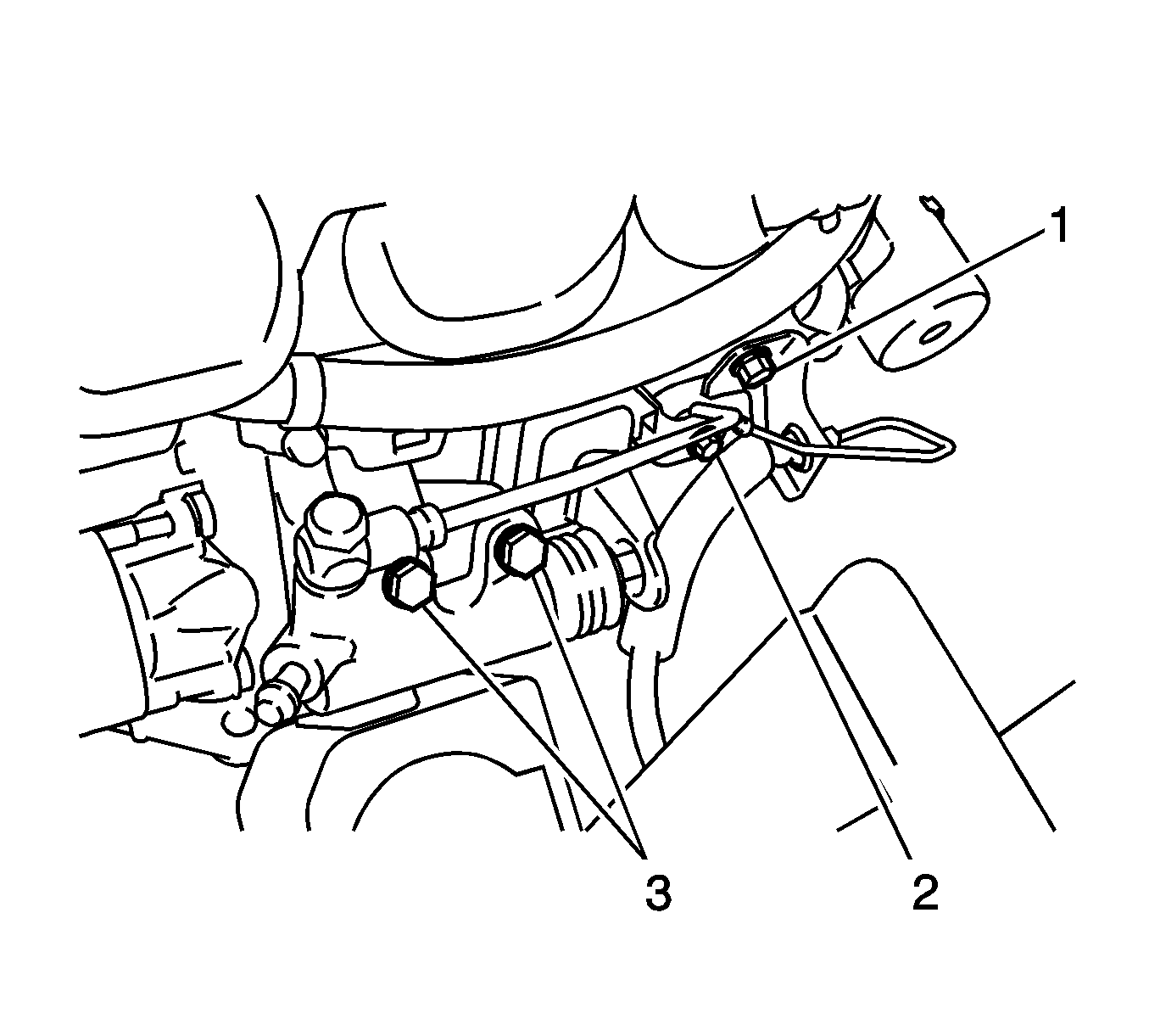
| • | bolt 3 to 12 N·m (9 lb ft) |
| • | bolt 1 to 12 N·m (9 lb ft) |
| • | bolt 2 to 8.0 N·m (71 lb in) |
Note: Align the fuel tube connector with the pipe, then push the fuel tube connector in until the retainer makes a click sound. If the connection is tight, apply a small amount of engine oil to the tip of the pipe. After connecting, pull on the pipe and connector to make sure that they are securely connected.




| • | the bolts to 6.5 N·m (58 lb in) |
| • | the nut to 3.5 N·m (31 lb in) |


Note: Be sure to engage the clips securely. Do not apply excessive force or do not hit the cover to engage the clips. This may cause the cover to break.
