Rear Disc Brake Pads Replacement All Wheel Drive and GT
Removal Procedure
- Use a siphon in order to remove half of the brake fluid from the master cylinder reservoir.
- Raise and support the vehicle. Refer to Lifting and Jacking the Vehicle.
- Remove the rear tire and wheel assembly from the vehicle. Refer to Tire and Wheel Removal and Installation.
- Install a large C-clamp over the brake caliper. Position the ends of the C-clamp against the rear of the caliper body and against the outer brake pad.
- Tighten the C-clamp in order to compress the caliper piston into the caliper bore.
- Remove the C-clamp from the caliper.
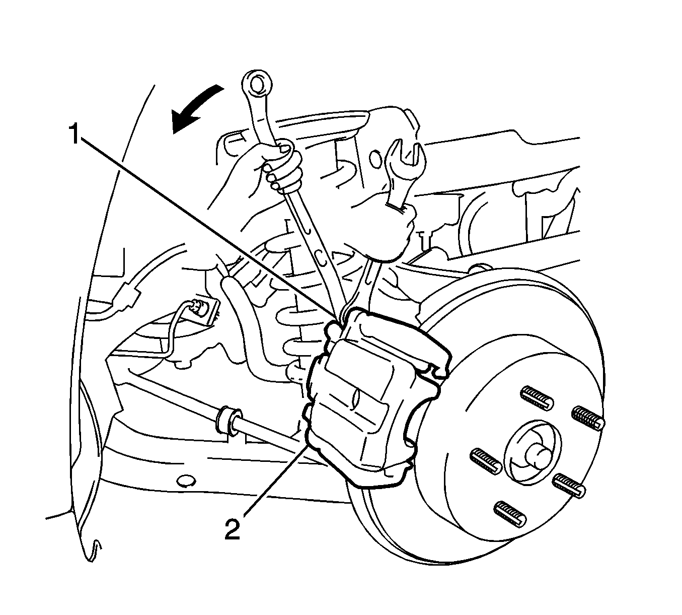
- Use a wrench in order to hold the caliper slide pins. Remove the caliper bolts (1, 2).
- Remove the caliper housing (2) from the caliper bracket. Support the caliper with a wire (1) in order to prevent damage to the brake hose.
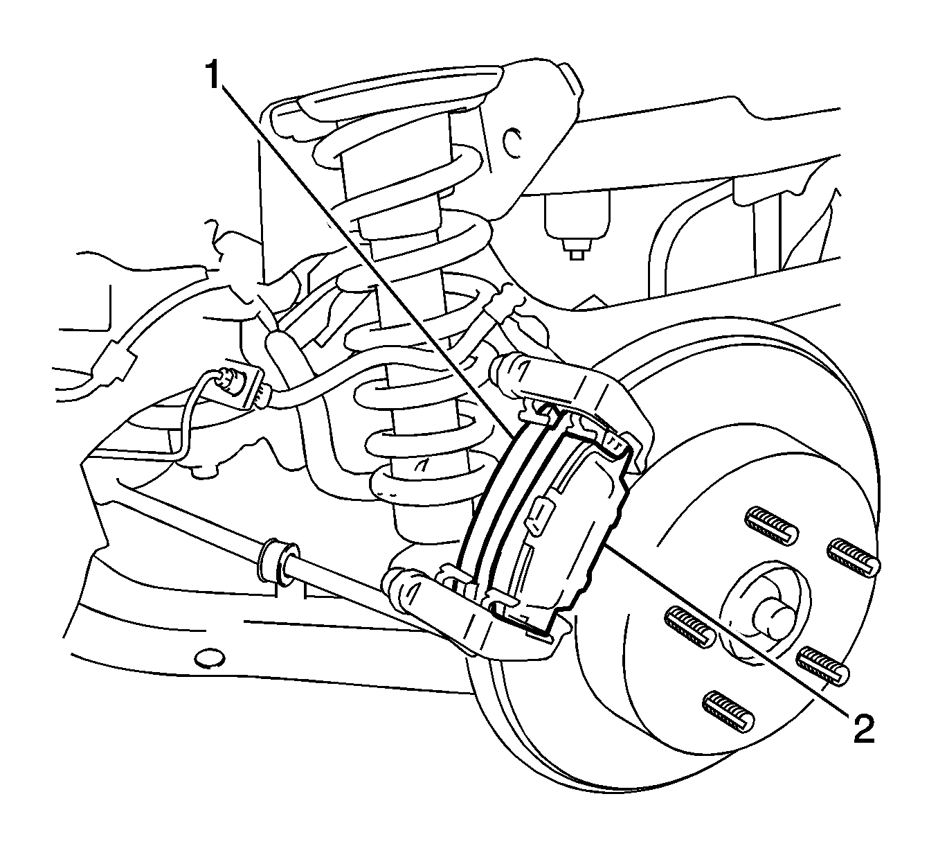
- Remove the brake pads (1) with the insulators (2).
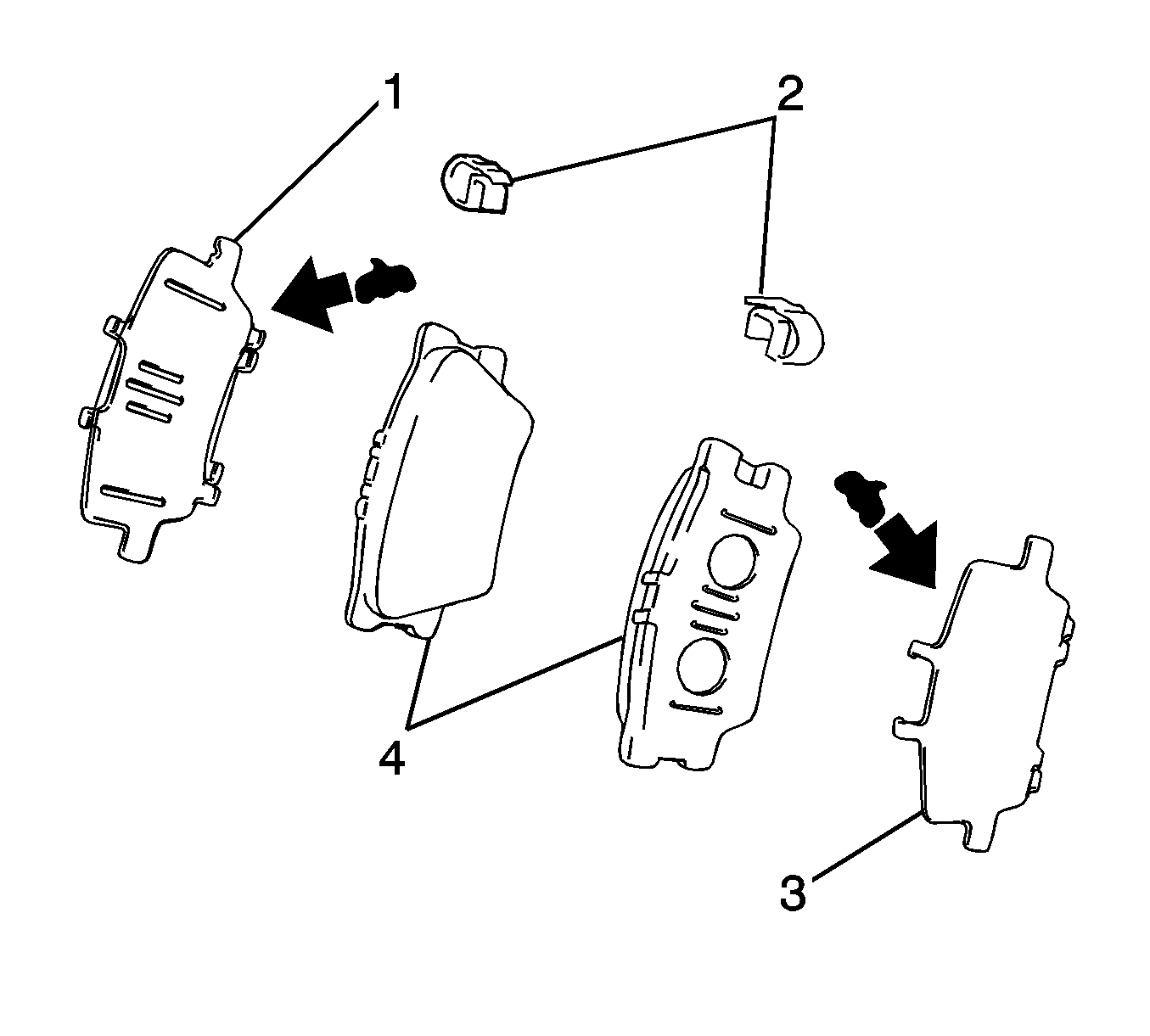
- Remove the wear indicators (2) and the insulators (1, 3) from the pads (4).
Warning: Refer to Brake Dust Warning in the Preface section.
Warning: Refer to Brake Fluid Irritant Warning in the Preface section.
Caution: Refer to Brake Fluid Effects on Paint and Electrical Components Caution in the Preface section.


Caution: Support the brake caliper with heavy mechanic wire, or equivalent, whenever it is separated from its mount and the hydraulic flexible brake hose is still connected. Failure to support the caliper in this manner will cause the flexible brake hose to bear the weight of the caliper, which may cause damage to the brake hose and in turn may cause a brake fluid leak.
Inspection Procedure
- Inspect the brake pads. If replacement is necessary, replace the disc brake pads in axle sets. Refer to Brake Pad Inspection.
- Clean and inspect the disc brake hardware. Replace components if necessary. Refer to Rear Disc Brake Mounting and Hardware Inspection.
- Clean and inspect the caliper. Repair or replace components as necessary. Refer to Brake Caliper Inspection.
- Measure the brake rotor thickness. Refinish or replace the rotor as necessary. Refer to Brake Rotor Thickness Measurement.
- Measure the brake rotor thickness variation. Refinish or replace the rotor as necessary. Refer to Brake Rotor Thickness Variation Measurement.
- Inspect the surface of the brake rotor. Refinish or replace the rotor as necessary. Refer to Brake Rotor Surface and Wear Inspection.
- Measure the brake rotor assembled lateral runout. Refinish or replace the rotor as necessary. Refer to Brake Rotor Assembled Lateral Runout Measurement.
Note: Refinish or replace the rotor ONLY if the condition of the rotor requires service. DO NOT refinish the rotor if the brake pads are the only components requiring service.
Installation Procedure
- If the caliper piston is not compressed into the caliper bore, complete the following steps:
- Apply disc brake grease to the pad side of the 2 insulators (1, 3).
- Ensure the disc brake grease covers the area where the insulators contact the pads (1).
- Install the 2 insulators to the 2 brake pads.
- Install the 2 wear indicators to the 2 brake pads.
- Install the brake pads (1) with the insulators (2) and the wear indicators to the caliper bracket.
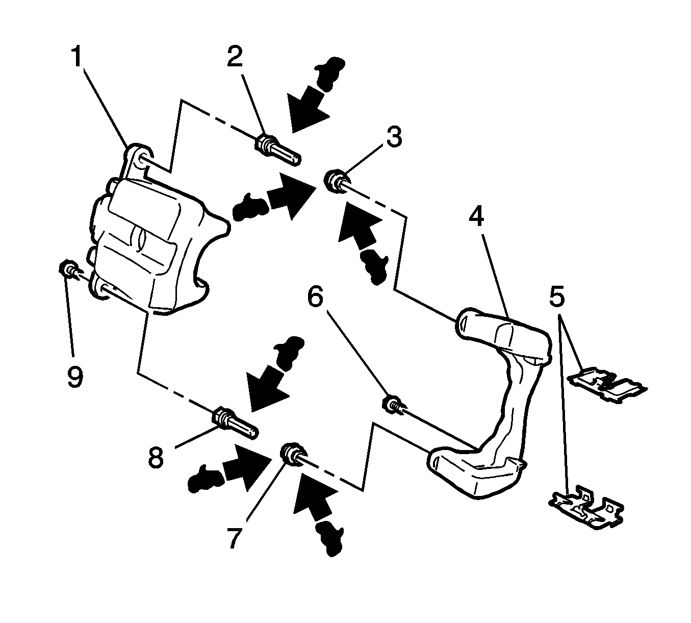
- Remove the wire from the caliper (1) and install the caliper to the caliper bracket (4).
- Use a wrench in order to hold the caliper slide pins (2, 8). Install the 2 bolts (9) and tighten to 27 N·m (20 lb ft).
- Install the rear tire and wheel assembly to the vehicle. Refer to Tire and Wheel Removal and Installation.
- Lower the vehicle.
- With the engine OFF, gradually apply and release the brake pedal several times in order to position the caliper pistons and the brake pads.
- Fill the master cylinder fluid reservoir. Refer to Master Cylinder Reservoir Filling.
- Burnish the pads and the rotors. Refer to Brake Pad and Rotor Burnishing.
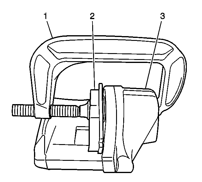
| 1.1. | Place an old brake pad (2) or a block of wood against the caliper piston. |
| 1.2. | Install a large C-clamp over the body of the brake caliper. |
| 1.3. | Position the ends of the C-clamp against the rear of the caliper body and against the pad or the wood. |
| 1.4. | Tighten the C-clamp in order to compress the caliper piston into the caliper bore. |
| 1.5. | Remove the C-clamp. |


Caution: Refer to Fastener Caution in the Preface section.
Rear Disc Brake Pads Replacement Except All Wheel Drive and GT
Removal Procedure
- Loosen the park brake system. Refer to Park Brake Adjustment.
- Use a siphon in order to remove half of the brake fluid from the master cylinder reservoir.
- Raise and support the vehicle. Refer to Lifting and Jacking the Vehicle.
- Remove the rear tire and wheel assembly from the vehicle. Refer to Tire and Wheel Removal and Installation.
- Use a wrench in order to hold the caliper slide pins (2, 9). Remove the caliper bolts (1, 10).
- Remove the caliper housing (2) from the caliper bracket. Support the caliper with a wire (1) in order to prevent damage to the brake hose.
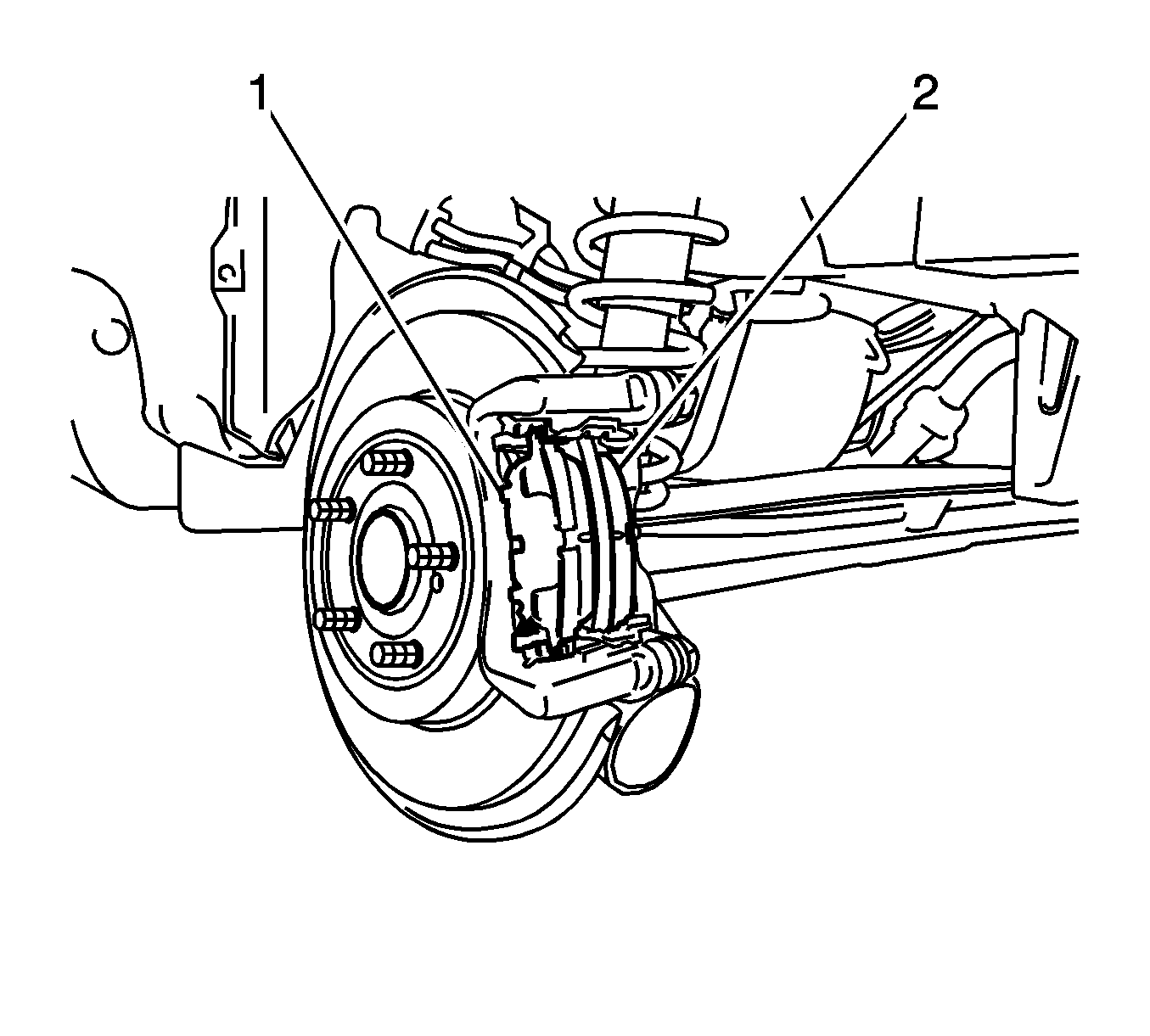
- Remove the brake pads (2) with the insulators (1).
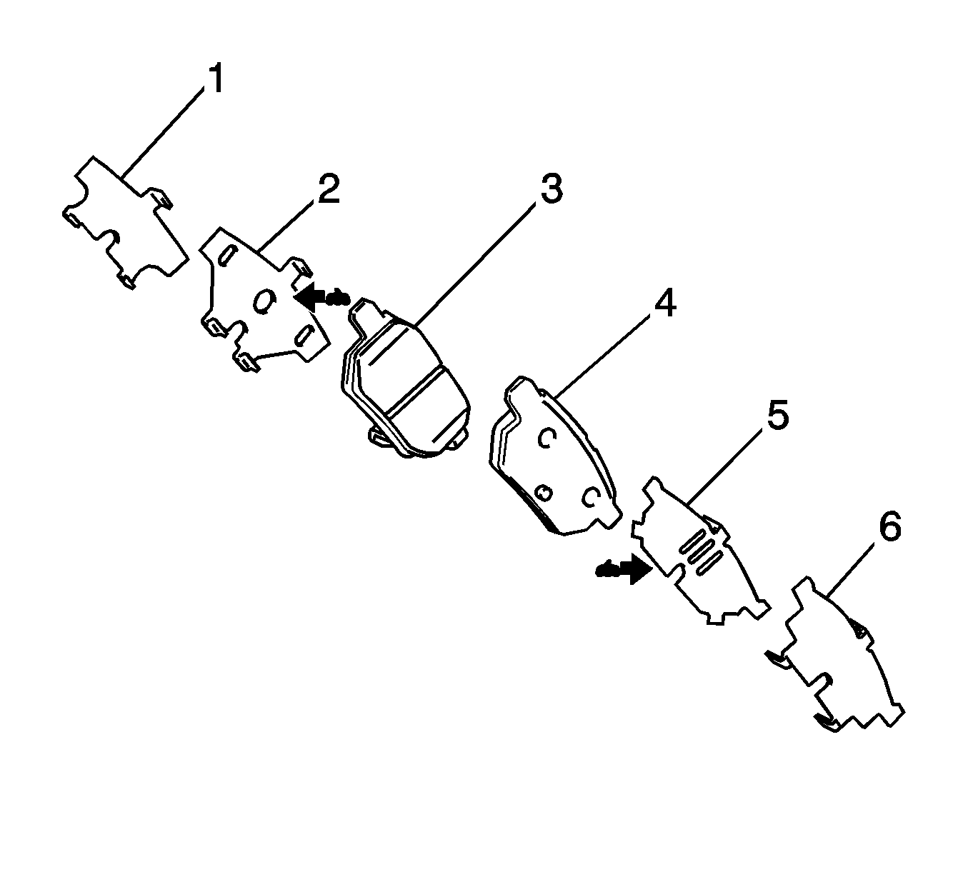
- Remove the insulators (1, 2, 5, 6) from the pads (3, 4).
Warning: Refer to Brake Dust Warning in the Preface section.
Warning: Refer to Brake Fluid Irritant Warning in the Preface section.
Caution: Refer to Brake Fluid Effects on Paint and Electrical Components Caution in the Preface section.

Caution: Support the brake caliper with heavy mechanic wire, or equivalent, whenever it is separated from its mount and the hydraulic flexible brake hose is still connected. Failure to support the caliper in this manner will cause the flexible brake hose to bear the weight of the caliper, which may cause damage to the brake hose and in turn may cause a brake fluid leak.
Inspection Procedure
- Inspect the brake pads. If replacement is necessary, replace the disc brake pads in axle sets. Refer to Brake Pad Inspection.
- Clean and inspect the disc brake hardware. Replace components if necessary. Refer to Rear Disc Brake Mounting and Hardware Inspection.
- Clean and inspect the caliper. Repair or replace components as necessary. Refer to Brake Caliper Inspection.
- Measure the brake rotor thickness. Refinish or replace the rotor as necessary. Refer to Brake Rotor Thickness Measurement.
- Measure the brake rotor thickness variation. Refinish or replace the rotor as necessary. Refer to Brake Rotor Thickness Variation Measurement.
- Inspect the surface of the brake rotor. Refinish or replace the rotor as necessary. Refer to Brake Rotor Surface and Wear Inspection.
- Measure the brake rotor assembled lateral runout. Refinish or replace the rotor as necessary. Refer to Brake Rotor Assembled Lateral Runout Measurement.
Note: Refinish or replace the rotor ONLY if the condition of the rotor requires service. DO NOT refinish the rotor if the brake pads are the only components requiring service.
Installation Procedure
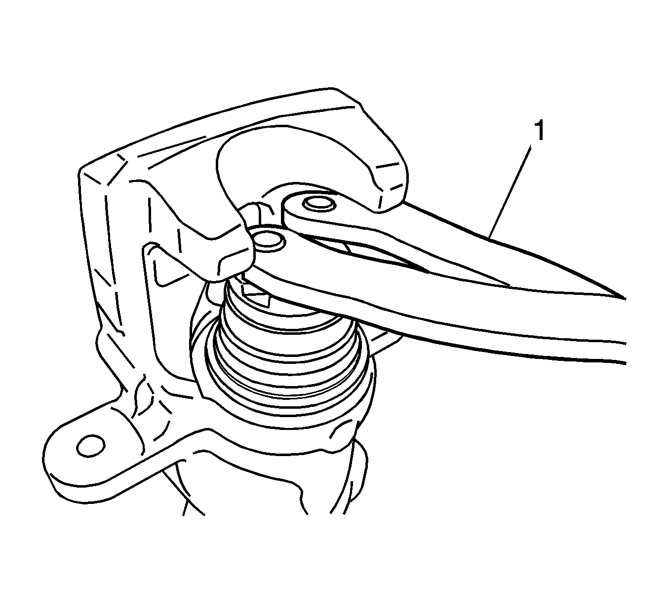
- If the caliper piston is not compressed enough into the bore in order to install the caliper, use a commercially available caliper piston tool (1) in order to turn the piston in as far as possible.
- Turn the piston in order to align the piston groove 90 degrees (a) from the line between the caliper slide pin bores.
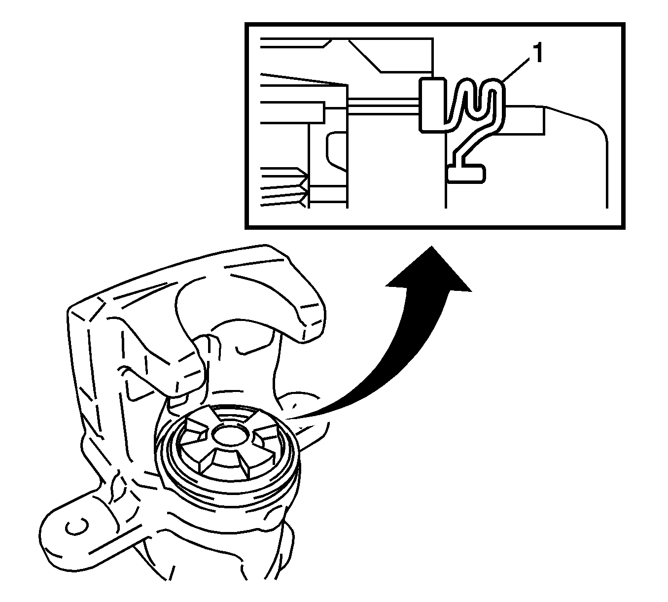
- Ensure the cylinder boot (1) is installed in the groove of the piston. If necessary, refer to Rear Brake Caliper Overhaul.
- Apply disc brake grease to the pad side of the 2 inner insulators (2, 5).
- Ensure the disc brake grease covers the area where the inner insulators contact the brake pads (3, 4).
- Install the 2 inner insulators to the 2 brake pads.
- Install the 2 outer insulators (1, 6) to the 2 inner insulators.
- Install the brake pads (2) with the insulators (1) to the caliper bracket.
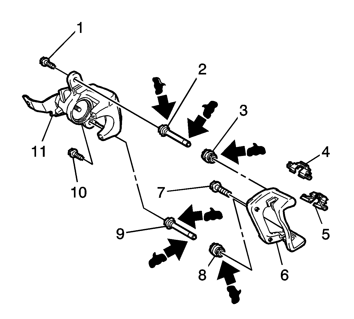
- Remove the wire from the caliper (11) and install the caliper to the caliper bracket (6).
- Use a wrench in order to hold the caliper slide pins (2, 9). Install the 2 bolts (1, 10) and tighten to 35 N·m (26 lb ft).
- Install the rear tire and wheel assembly to the vehicle. Refer to Tire and Wheel Removal and Installation.
- Lower the vehicle.
- With the engine OFF, gradually apply and release the brake pedal several times in order to position the caliper pistons and the brake pads.
- Fill the master cylinder fluid reservoir. Refer to Master Cylinder Reservoir Filling.
- Adjust the park brake system. Refer to Park Brake Adjustment.
- Burnish the pads and the rotors. Refer to Brake Pad and Rotor Burnishing.
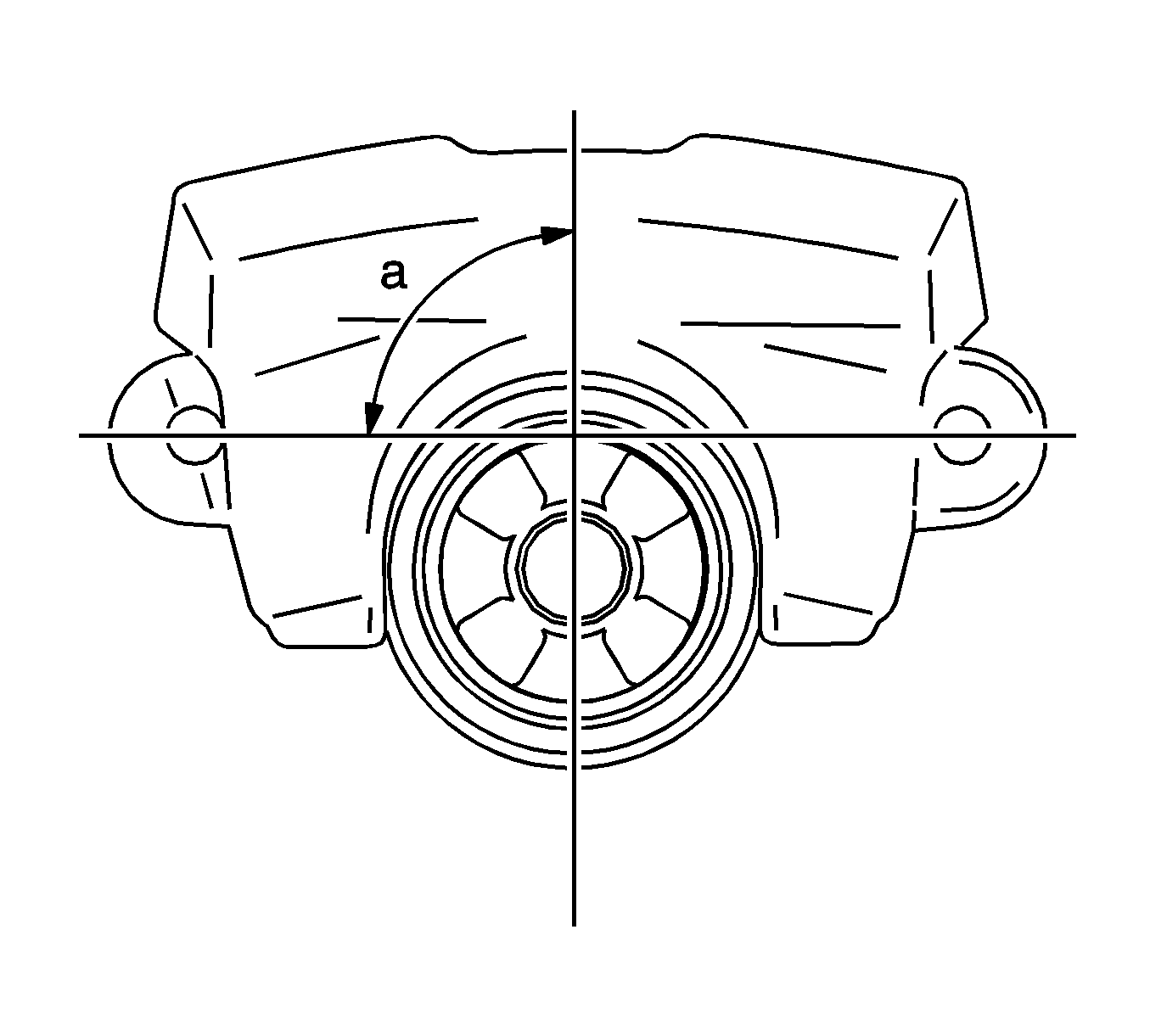
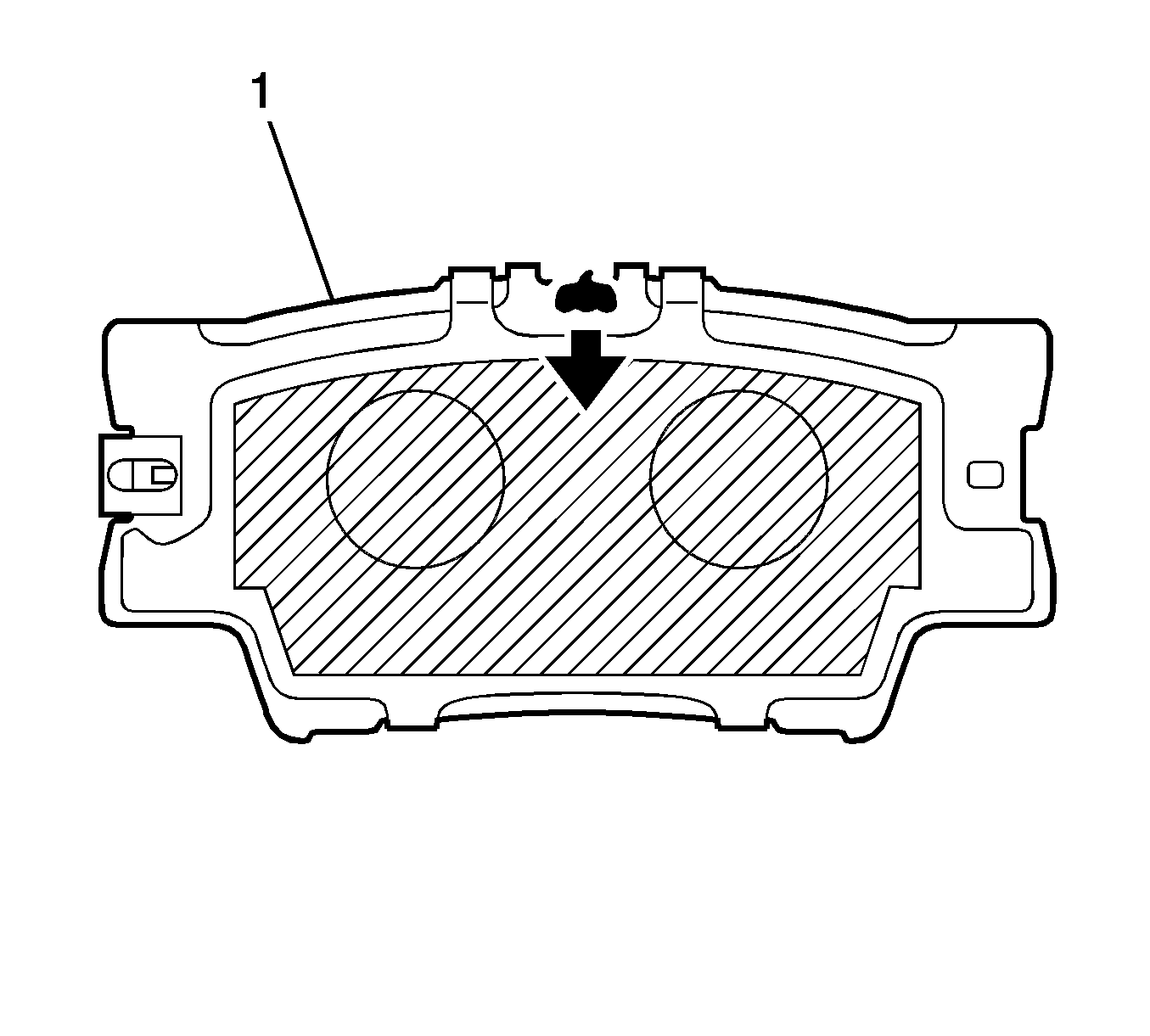
Align the piston groove with the protrusion in the brake pad.


Caution: Refer to Fastener Caution in the Preface section.
