Removal Procedure
- Remove the engine assembly with transaxle. Refer to Engine Replacement
- Install the engine stand.
- Remove the intake manifold. Refer to Intake Manifold Replacement.
- Disconnect the fuel tube assembly.
- Remove the fuel delivery pipe assembly.
- Remove the fuel injector assembly.
- Remove the ignition coil assembly.
- Remove the oil level dipstick sub-assembly.
- Remove the exhaust manifold. Refer to Exhaust Manifold Replacement.
- Remove the ventilation hose.
- Remove the water by-pass pipe.
- Remove the water by-pass hoses.
- Remove the inlet water hose.
- Remove the inlet water.
- Remove the thermostat.
- Remove the radio setting condenser.
- Remove the cylinder head cover. Refer to Camshaft Cover Replacement.
- Set the No. 1 cylinder to TDC/compression.
- Remove the crankshaft pulley.
- Remove the chain tensioner assembly.
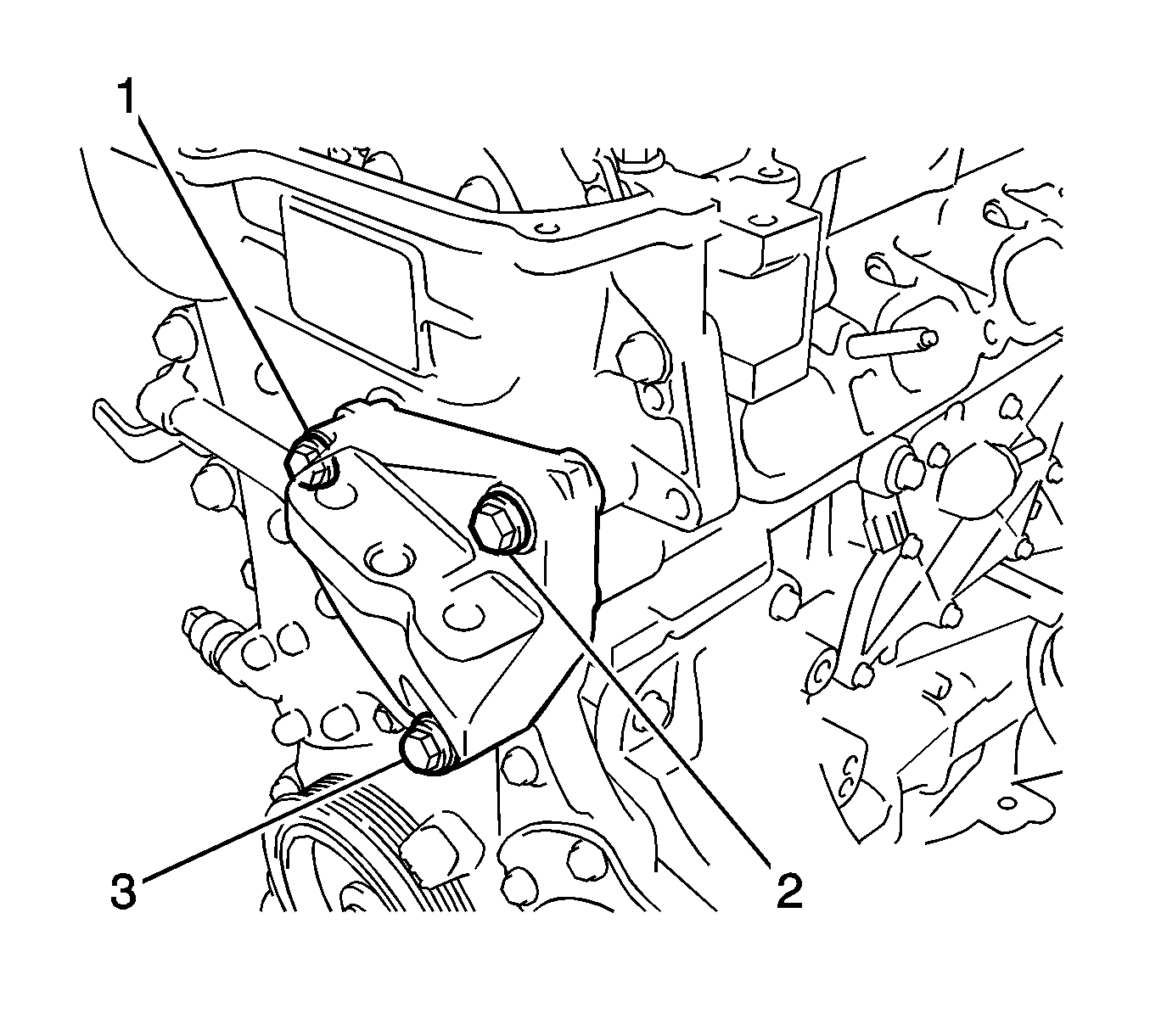
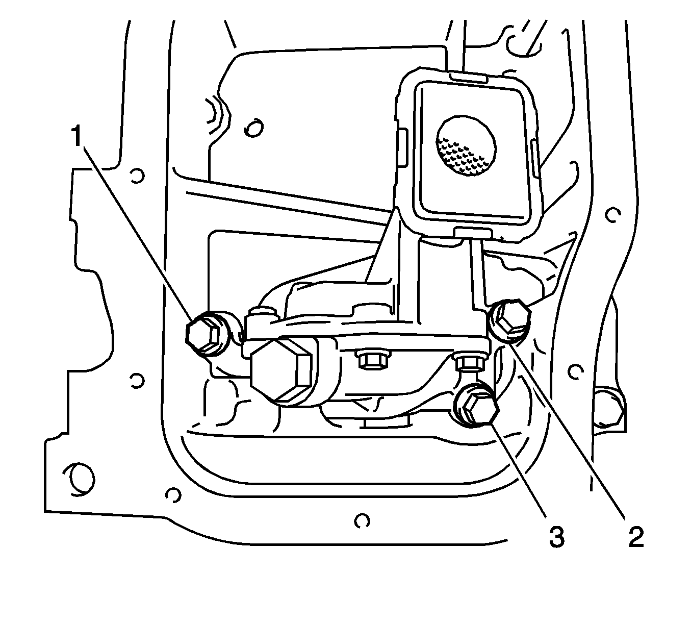
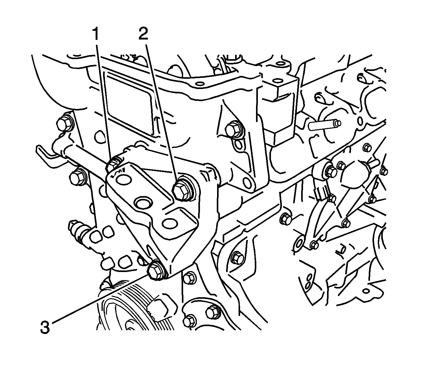
- Remove the 3 bolts (1-3) and engine mounting bracket.
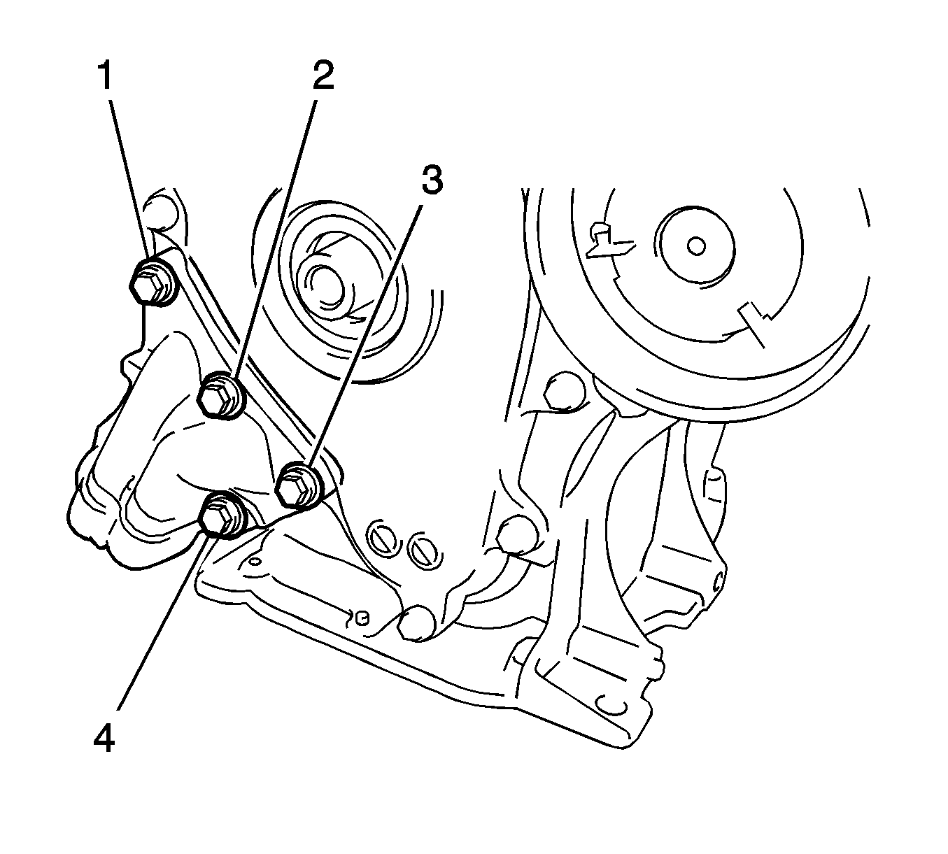
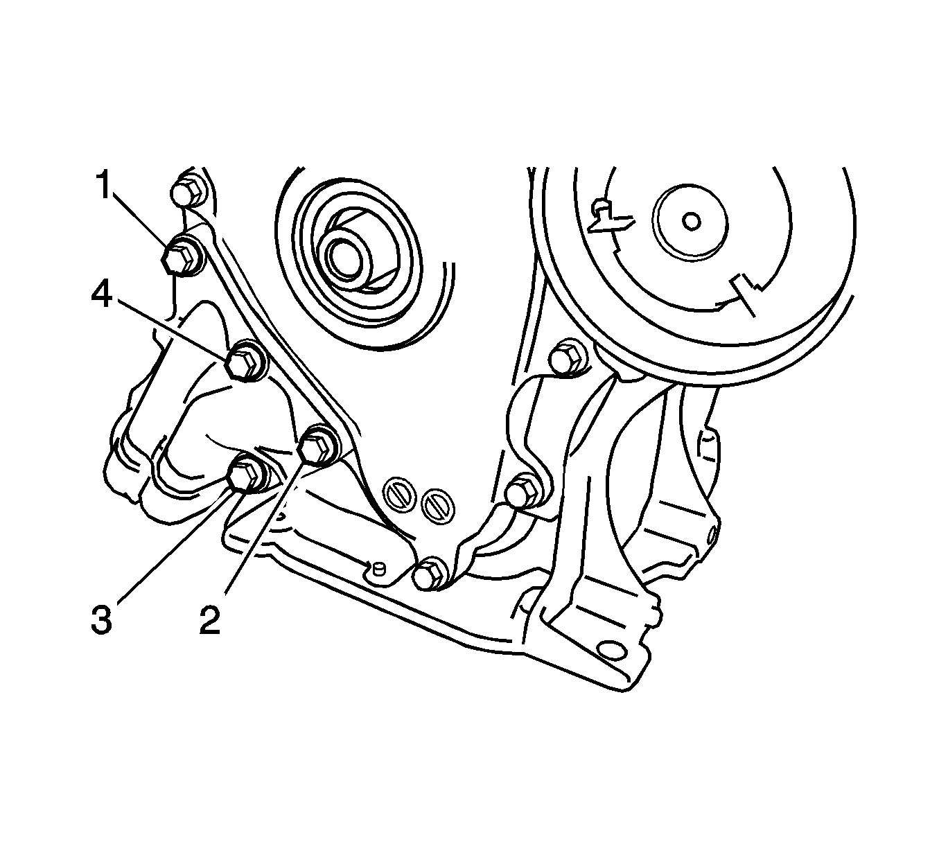
- Remove the 4 bolts (1-4) and oil filter bracket.
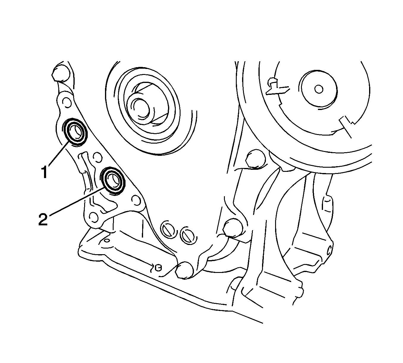
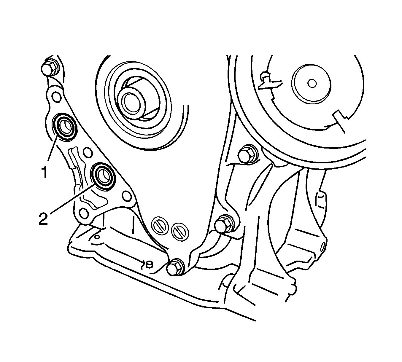
- Remove the 2 O-rings (1-2).
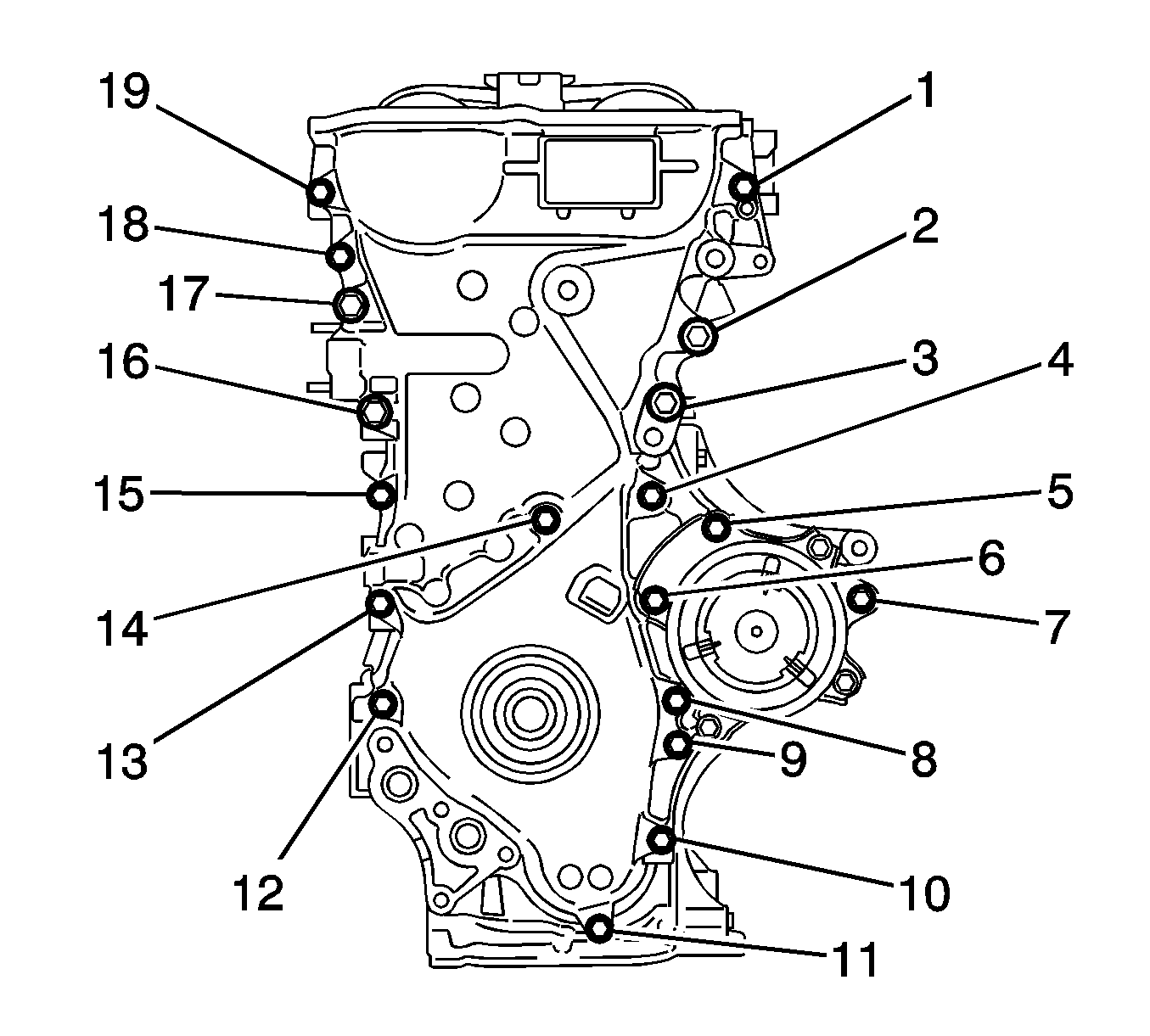
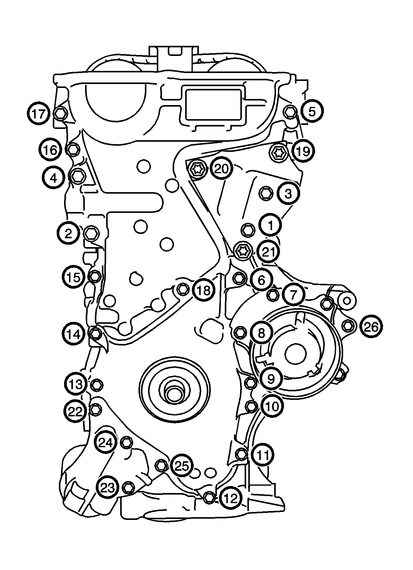
- Remove the 19 bolts (1-19).
- Remove the timing chain cover by prying between the timing chain cover and cylinder head or cylinder block with a screwdriver.
- Remove the 3 O-rings (1-3).
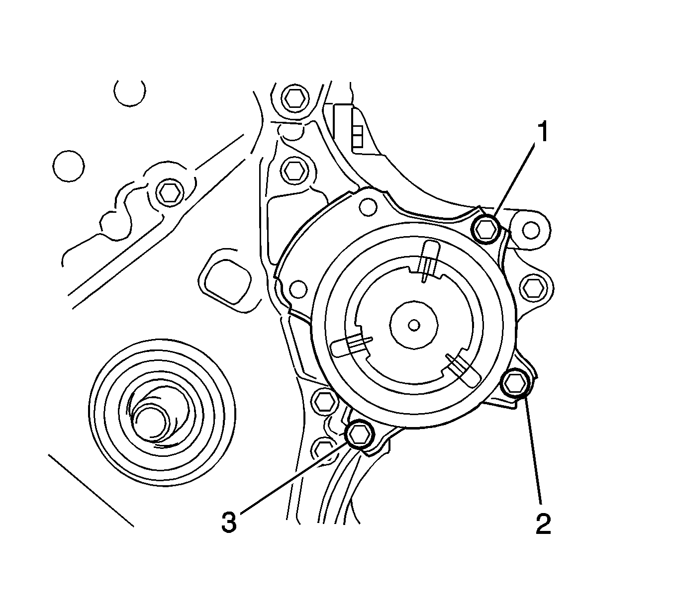
- Remove the 3 bolts (1-3) and water pump.
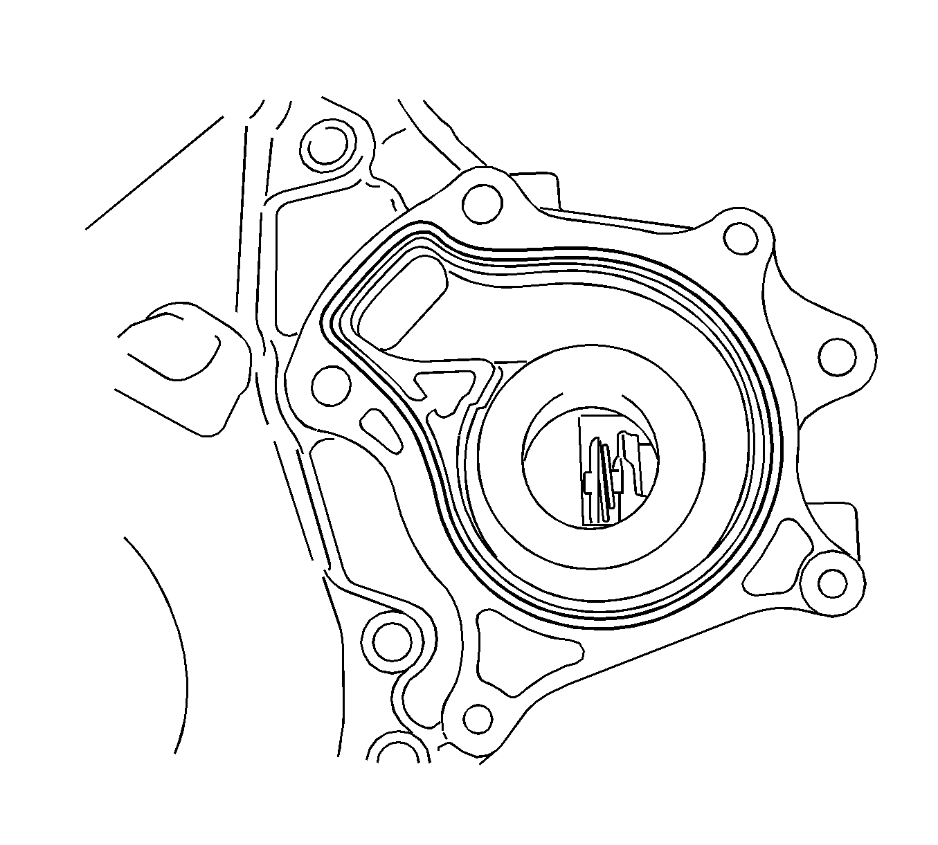
- Remove the gasket.
- Place the timing chain cover on wooden blocks (1).
- Using a screwdriver, pry out the oil seal.
- Remove the chain tensioner slipper.
- Remove the chain vibration damper.
- Remove the chain assembly.
- Remove the 2 bolts (1) and chain vibration damper.
- Hand tighten the crank pulley bolt.
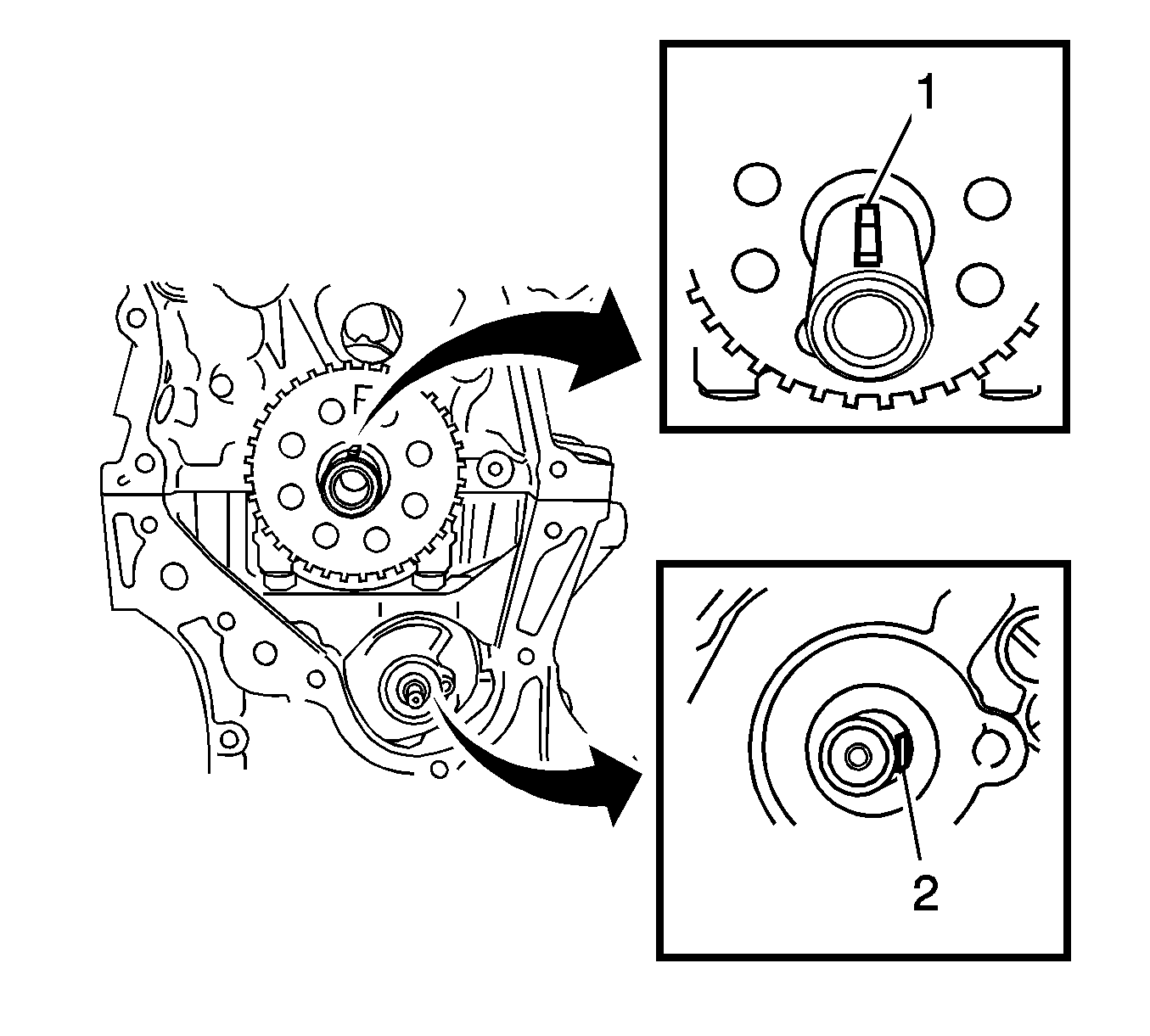
- Turn the crankshaft 90 degrees clockwise to align the adjusting hole (1) of the oil pump drive shaft sprocket with the groove of the oil pump.
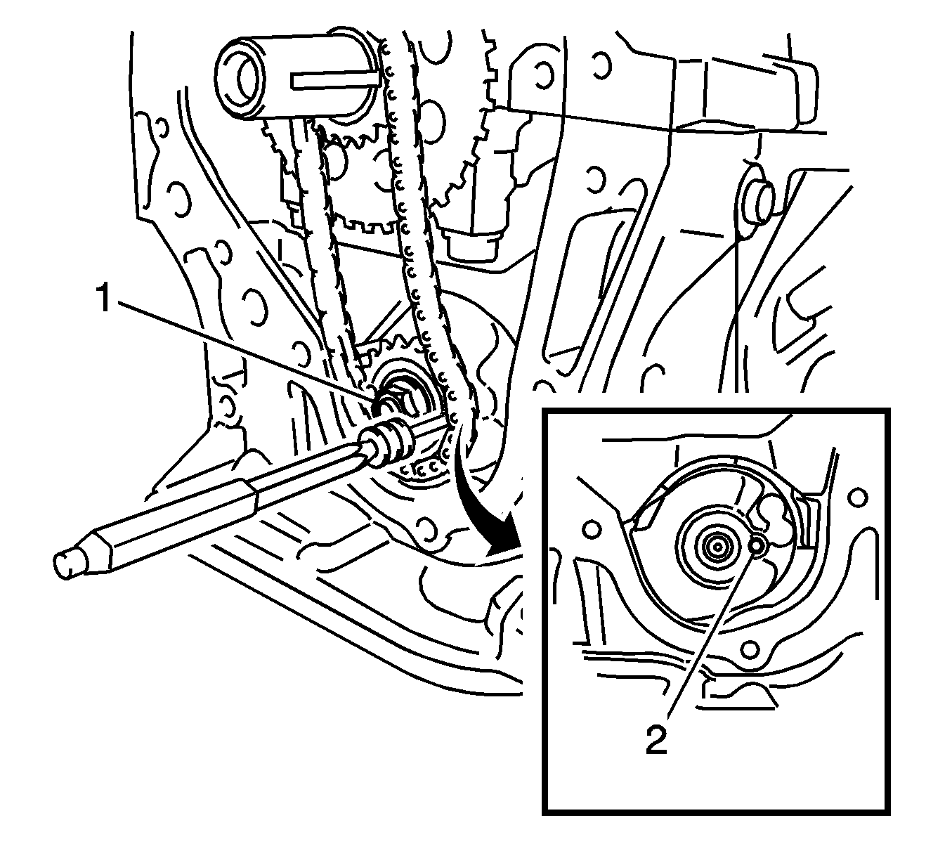
- Remove the crank pulley bolt.
- Insert a pin punch (3 mm) into the adjusting hole (2) of the oil pump drive shaft sprocket (1) to lock the gear in position, and then remove the nut.
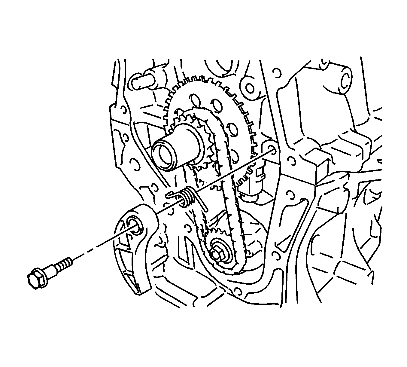
- Remove the bolt, chain tensioner plate, and spring.
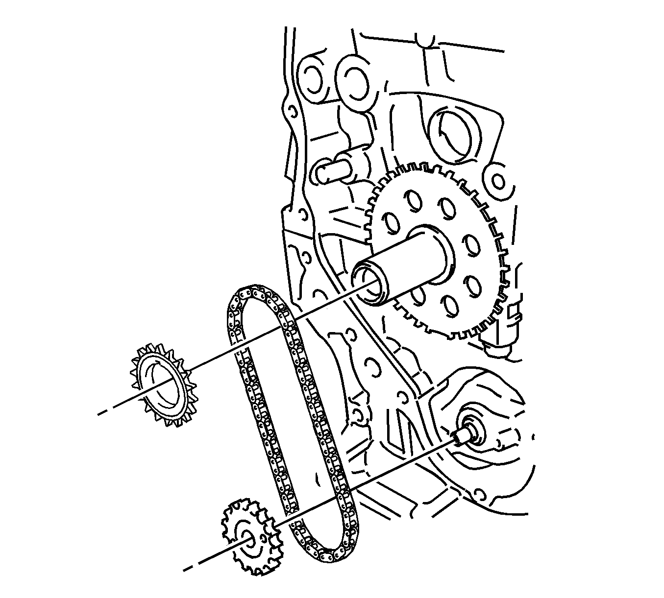
- Remove the crankshaft timing sprocket, oil pump drive shaft gear, and chain assembly.
- Remove the crankshaft position sensor plate.
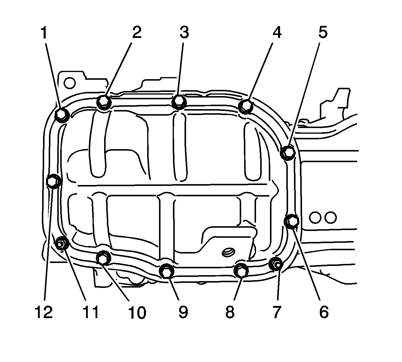
- Remove the 10 bolts (1-6, 8-10, 12) and 2 nuts (7, 11).
- Insert the blade of oil pan seal cutter between the crankcase and oil pan. Cut through the sealer and remove the oil pan.
- Remove the 3 bolts (1, 2, 3) and oil pump.
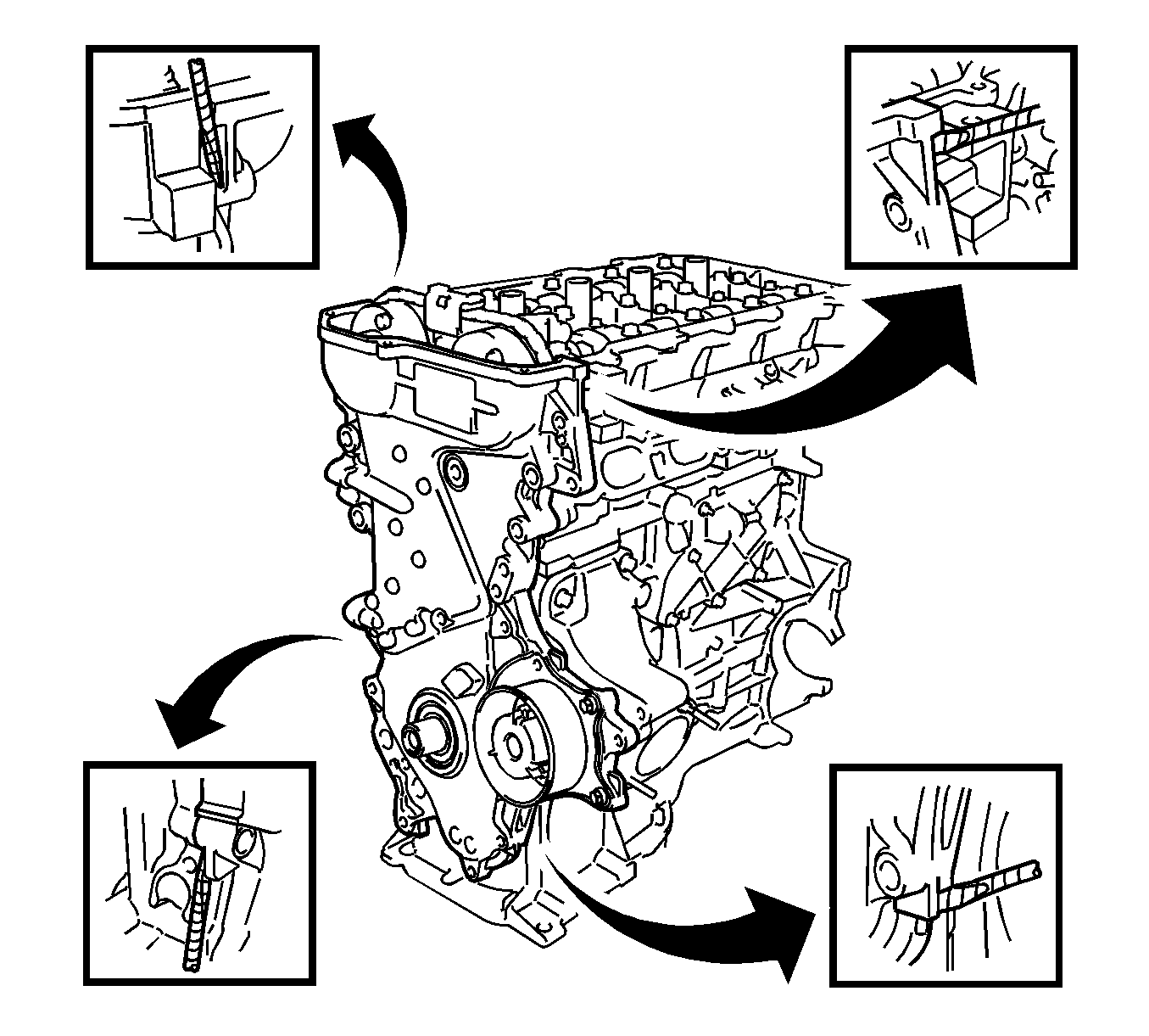
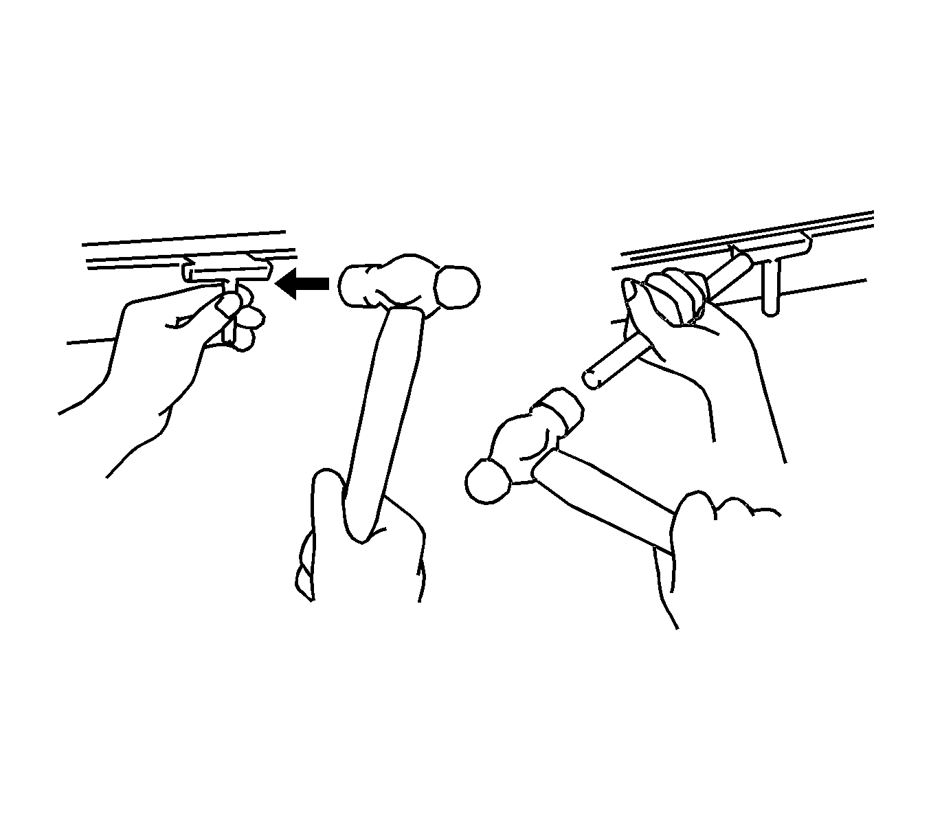
Note: Tape the screwdriver tip before use.
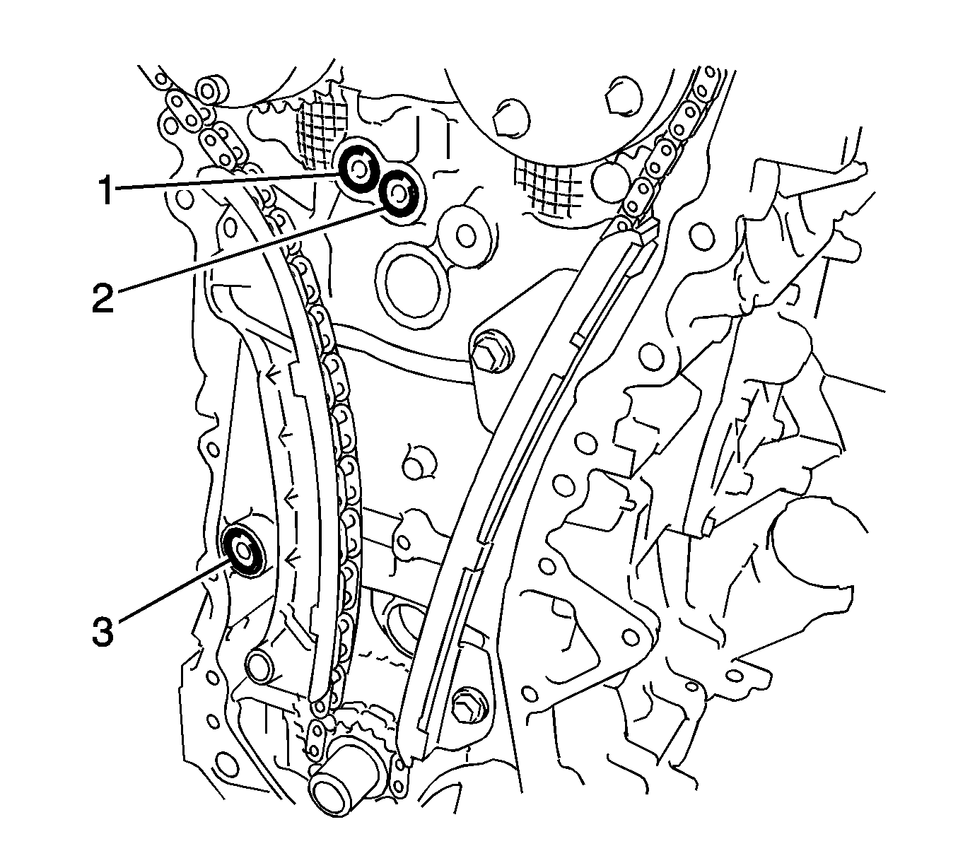
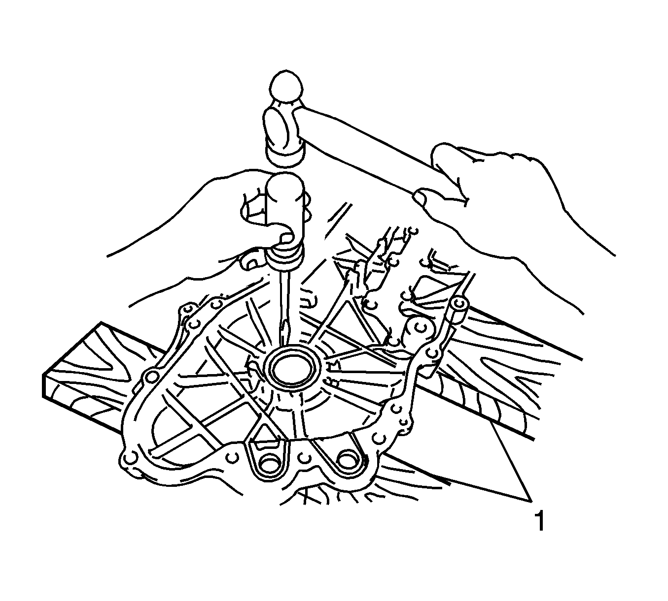
Note: Tape the screwdriver tip before use.
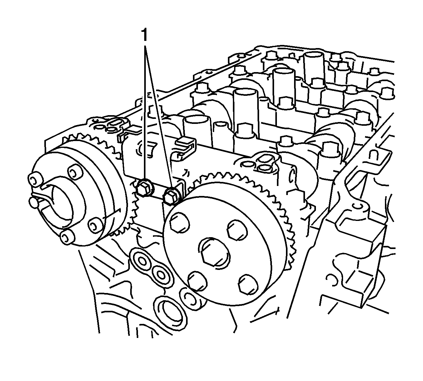
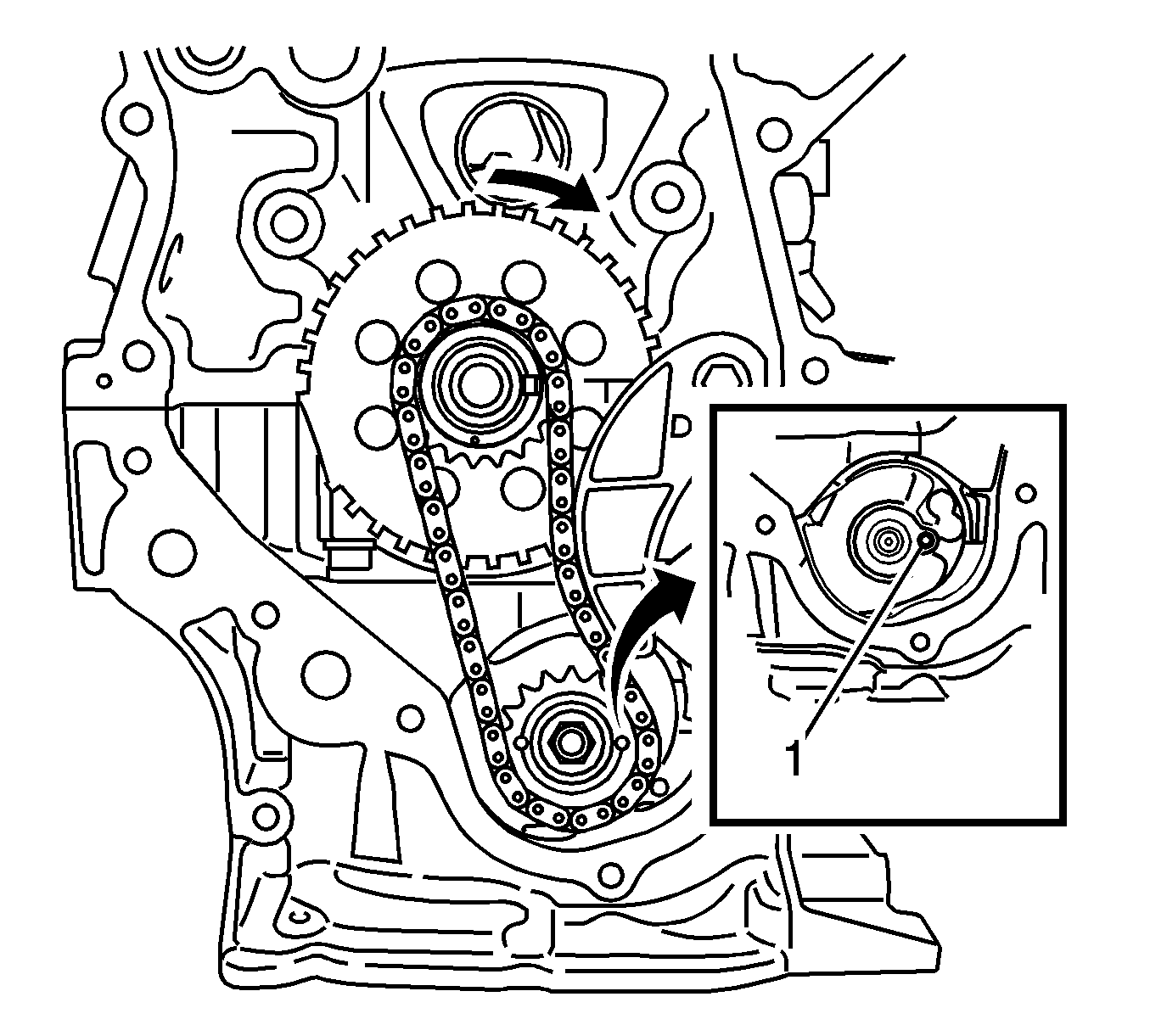
Note: Do not rotate the crankshaft more than 90 degrees. If the crankshaft is rotated too much without the timing chain installed, the valves may hit the pistons and cause damage.
Note: Be careful not to damage the contact surfaces of the crankcase, chain cover, and oil pan.
Installation Procedure
- Install the oil pump with the 3 bolts (1-3) and tighten to 21 N·m (16 lb ft).
- Remove any old sealing material and be careful not to drop any oil on the contact surfaces of the cylinder block and oil pan.
- Apply a continuous bead of sealant (1), diameter: 4.0 mm (0.157 in), as shown in the illustration, Three Bond 1217B, or equivalent, GM part number 12378521 (Canadian part number 88901148).
- Install the No. 2 oil pan with the 10 bolts (1-6, 8-10, 12) and 2 nuts (7, 11) and tighten to 10 N·m (7 lb ft).
- Install the crankshaft position sensor plate.
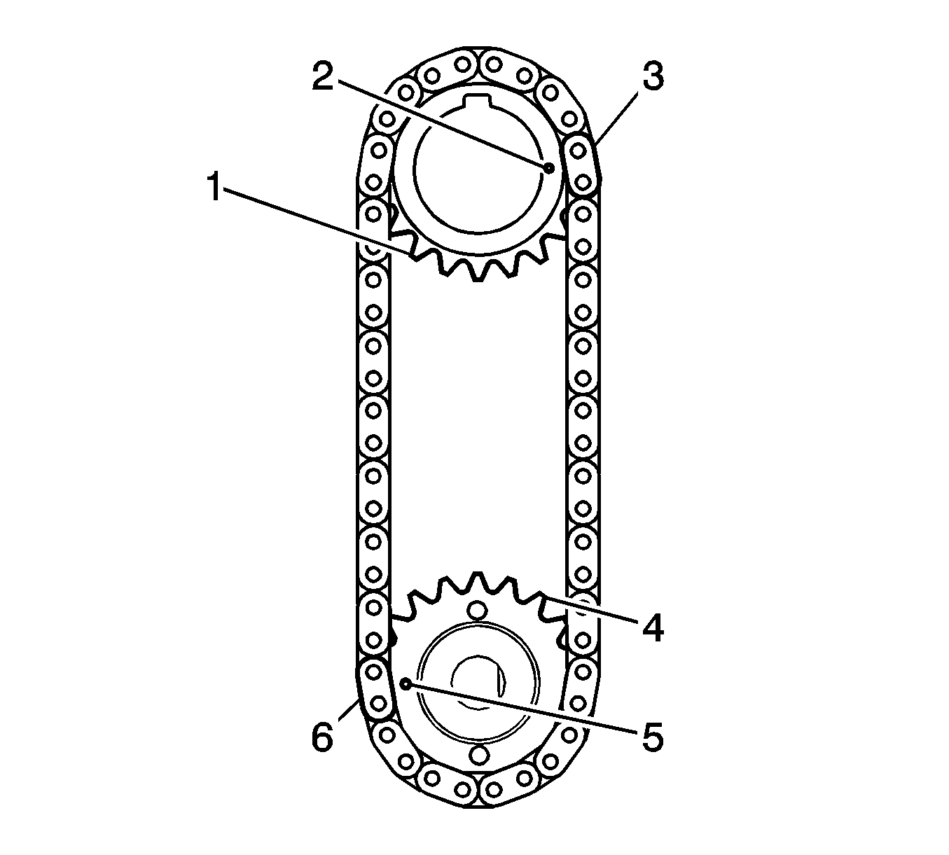
- Set the crankshaft key (1).
- Turn the drive shaft (2) so that the cutout faces right horizontal position.
- Align the yellow mark links (3, 6) with the timing marks (2, 5) of each gear.
- Install the sprockets onto the crankshaft and oil pump shaft with the chain on the gears.
- Hand tighten the oil pump drive shaft sprocket with the nut.
- Insert the damper spring into the adjusting hole, and then install the chain tensioner plate with the bolt and tighten to 10 N·m (7 lb ft).
- Align the adjusting hole of the oil pump drive shaft sprocket (1) with the groove of the oil pump.
- Insert a pin punch (3 mm) into the adjusting hole (2) of the oil pump drive shaft gear to lock the gear in position, and then tighten the nut (1) to 28 N·m (21 lb ft).
- Install the chain vibration damper with the 2 bolts (1) and tighten to 10 N·m (7 lb ft).
- Install the chain sub-assembly.
- Install the chain tensioner slipper.
- Apply MP grease to the lip of the oil seal.
- Remove any old sealant material and be careful not to drop any oil on the contact surfaces of the timing chain cover sub-assembly, cylinder head, and cylinder block.
- Install the 3 new O-rings (1-3).
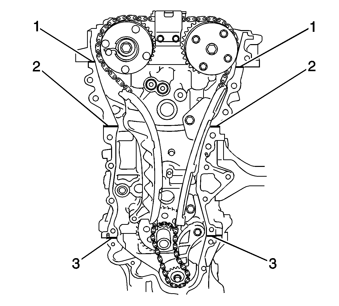
- Apply Three Bond 1217B, or equivalent, GM part number 12378521 (Canadian part number 88901148) to the parting lines of the camshaft housing (1), cylinder head (2) and lower crankcase (3)
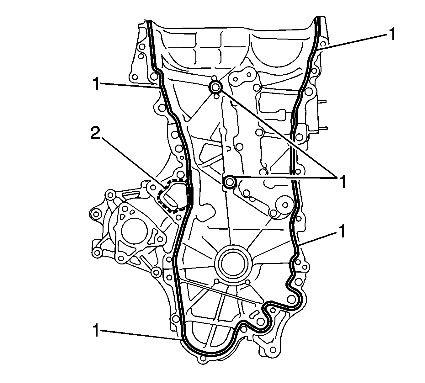
- Apply sealant to the timing chain cover in a continuous line as follows:
- Hand install the timing chain cover subassembly with the 19 bolts.
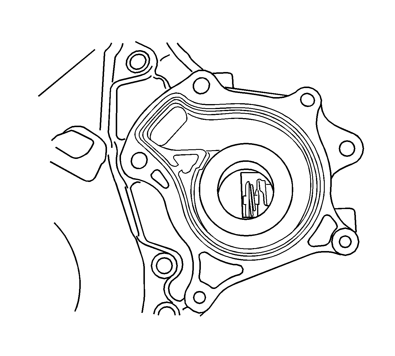
- Install a new gasket.
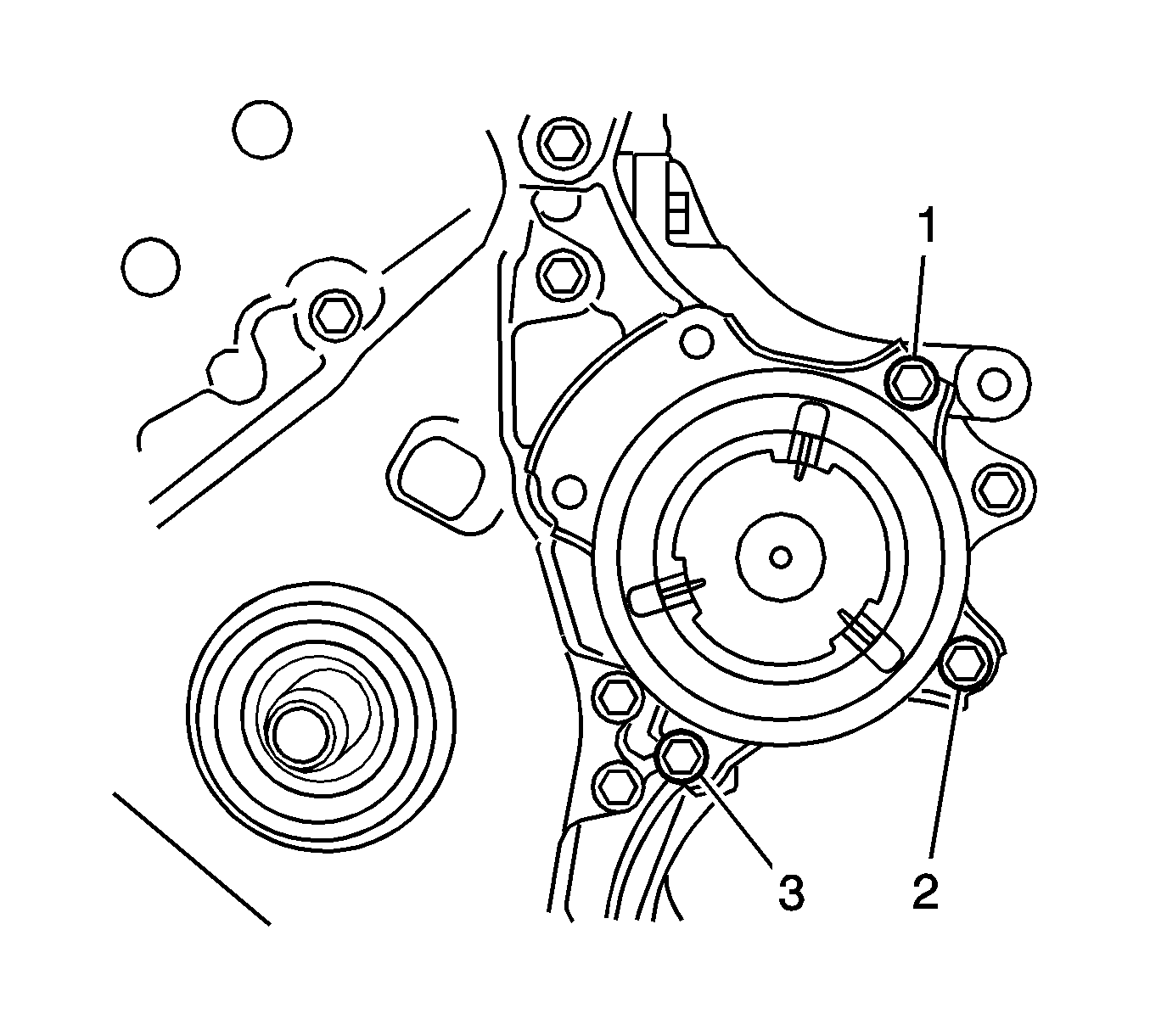
- Install the water pump with the 3 bolts (1, 2, 3) and tighten to 24 N·m (18 lb ft).
- Install the mounting bracket within 10 minutes after installing the timing chain cover assembly.
- Hand tighten the engine mounting bracket with the 3 bolts (1, 2, 3).
- Install 2 new O-rings (1, 2).
- Install the oil filter bracket within 10 minutes after installing the chain cover.
- Temporarily tighten the oil filter bracket with the 4 bolts (1-4).
- Apply Three Bond 1324 or equivalent to the threads of the bolt 5.
- Install the chain cover within 3 minutes and tighten the bolts within 15 minutes after applying the sealant.
- Torque the bolts in the above sequence.
- Fully tighten the timing chain cover sub-assembly with the 26 bolts.
- Install the crankshaft pulley.
- Install the chain tensioner assembly.
- Install the cylinder head cover. Refer to Camshaft Cover Replacement.
- Install the radio setting condenser.
- Install the thermostat.
- Install the inlet water.
- Install the inlet water hose.
- Install the water by-pass hoses.
- Install the water by-pass pipe.
- Install the ventilation hose.
- Install the exhaust manifold. Refer to Engine Flywheel Installation.
- Install the oil level dipstick assembly.
- Install the ignition coil assembly.
- Install the fuel injector assembly.
- Install the delivery pipe spacer.
- Install the fuel delivery pipe assembly.
- Install the fuel tube assembly.
- Install the intake manifold. Refer to Intake Manifold Replacement.
- Remove the engine stand.
- Install the engine assembly with transaxle. Refer to Engine Replacement.
Caution: Refer to Fastener Caution in the Preface section.

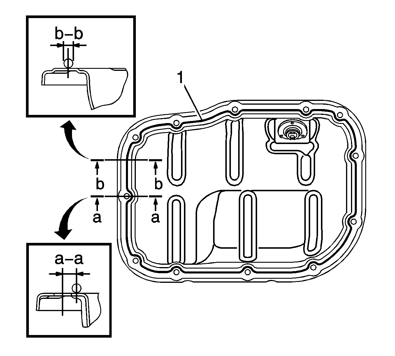
Note:
• Remove any oil from the contact surfaces. • Install the oil pan within 3 minutes after applying seal packing. • Do not start the engine for at least 2 hours after installing the oil pan.



Note:
• Remove any oil from the contact surfaces. • Install the chain cover within 3 minutes after applying sealant. • Do not start the engine for at least 2 hours after installing the timing chain cover sub-assembly.
Note:
• When the contact surfaces are wet, wipe them with oil-free cloth before applying sealant. • Install the timing chain cover sub-assembly within 3 minutes and tighten the bolts within 15 minutes after applying sealant. • Do not start the engine for at least 2 hours after installing.
Continuous Line Area (1)
| • | Sealant Diameter - 3.0 mm (0.118 in) |
| • | Application Position form Inside Seal Line - 2.5 mm (0.098 in) |
| • | Sealant - Three Bond 1207B or equivalent |
Dashed Line Area (2)
| • | Sealant Diameter - 4.0 mm (0.156 in) |
| • | Application Position form Inside Seal Line - 3.0 mm (0.118 in) |
| • | Sealant - Three Bond 1207B or equivalent |
Note: Remove any oil from the contact surfaces.
Note:
• When the contact surfaces are wet, wipe them with oil-free cloth before applying sealant. • Do not start the engine for at least 2 hours after installing
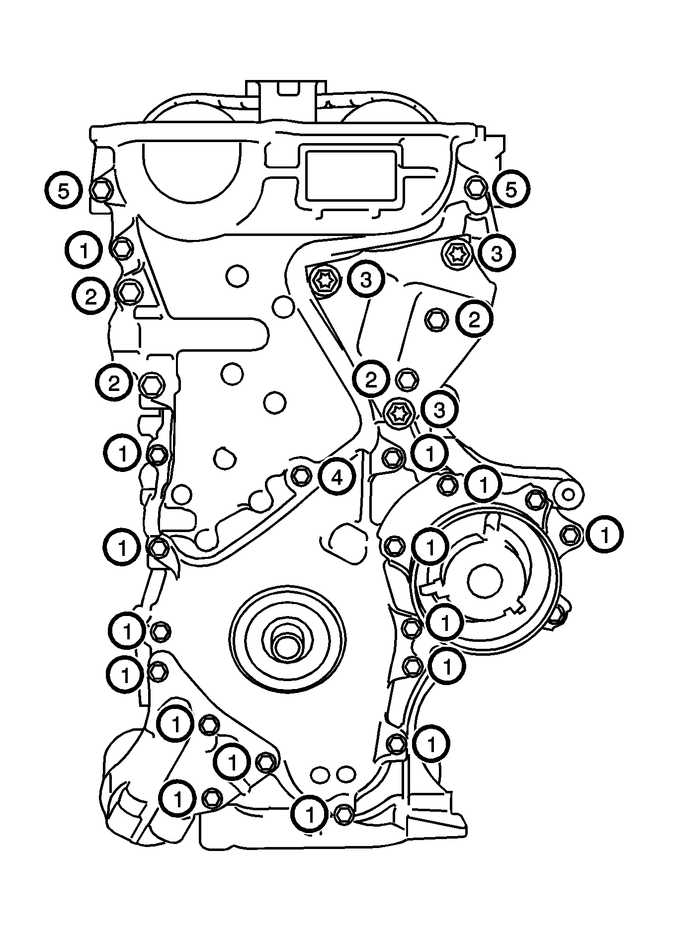
| • | bolts 1 and 5 to 26 N·m (19 lb ft) |
| • | bolts 2 and 3 to 51 N·m(37 lb ft) |
| • | bolt 4 to 10 N·m (7 lb ft) |
