Removal Procedure
- Discharge the fuel system pressure.
- Disconnect the cable from negative battery terminal. Refer to Battery Negative Cable Disconnection and Connection.
- Remove the windshield wiper motor and link assembly. Refer to Windshield Wiper Motor Replacement.
- Remove the outer cowl top panel.
- Remove the suspension tower damper assembly, with front strut bar.
- Remove the right front wheel.
- Remove the left engine under cover.
- Remove the right engine under cover.
- Remove the engine cover. Refer to Engine Cover Replacement.
- Drain the engine coolant. Refer to Cooling System Draining and Filling.
- Drain the engine oil. Refer to Engine Oil and Oil Filter Replacement.
- Remove the catalytic converter assembly. Refer to Catalytic Converter Replacement.
- Remove the front exhaust pipe assembly. Refer to Front Pipe Replacement.
- Remove the v-ribbed belt. Refer to Drive Belt Replacement.
- Remove the generator assembly. Refer to Generator Replacement.
- Disconnect the radiator hose.
- Disconnect the outlet heater water hose.
- Disconnect the inlet heater water hose.
- Separate the radiator reserve tank assembly.
- Remove the air cleaner cap with hose.
- Remove the throttle body assembly.
- Remove the ignition coil assembly. Refer to Ignition Coil Replacement.
- Remove the spark plug. Refer to Spark Plug Replacement.
- Remove the cylinder head cover. Refer to Camshaft Cover Replacement.
- Remove the engine oil level dipstick.
- Remove the engine oil level dipstick guide.
- Remove the fuel main tube.
- Remove the fuel delivery pipe sub-assembly.
- Remove the camshaft timing oil control valve assembly.
- Remove the intake manifold. Refer to Intake Manifold Replacement.
- Remove the intake manifold insulator.
- Remove the exhaust manifold converter. Refer to Exhaust Manifold Replacement.
- Remove the right engine mount.
- Remove the idler pulley.
- Remove the oil pan.
- Set the cylinder to TDC/compression.
- Remove the crankshaft pulley.
- Remove the chain tensioner assembly.
- Remove the transverse engine mounting bracket.
- Remove the v-ribbed belt tensioner assembly.
- Remove the crankshaft position sensor.
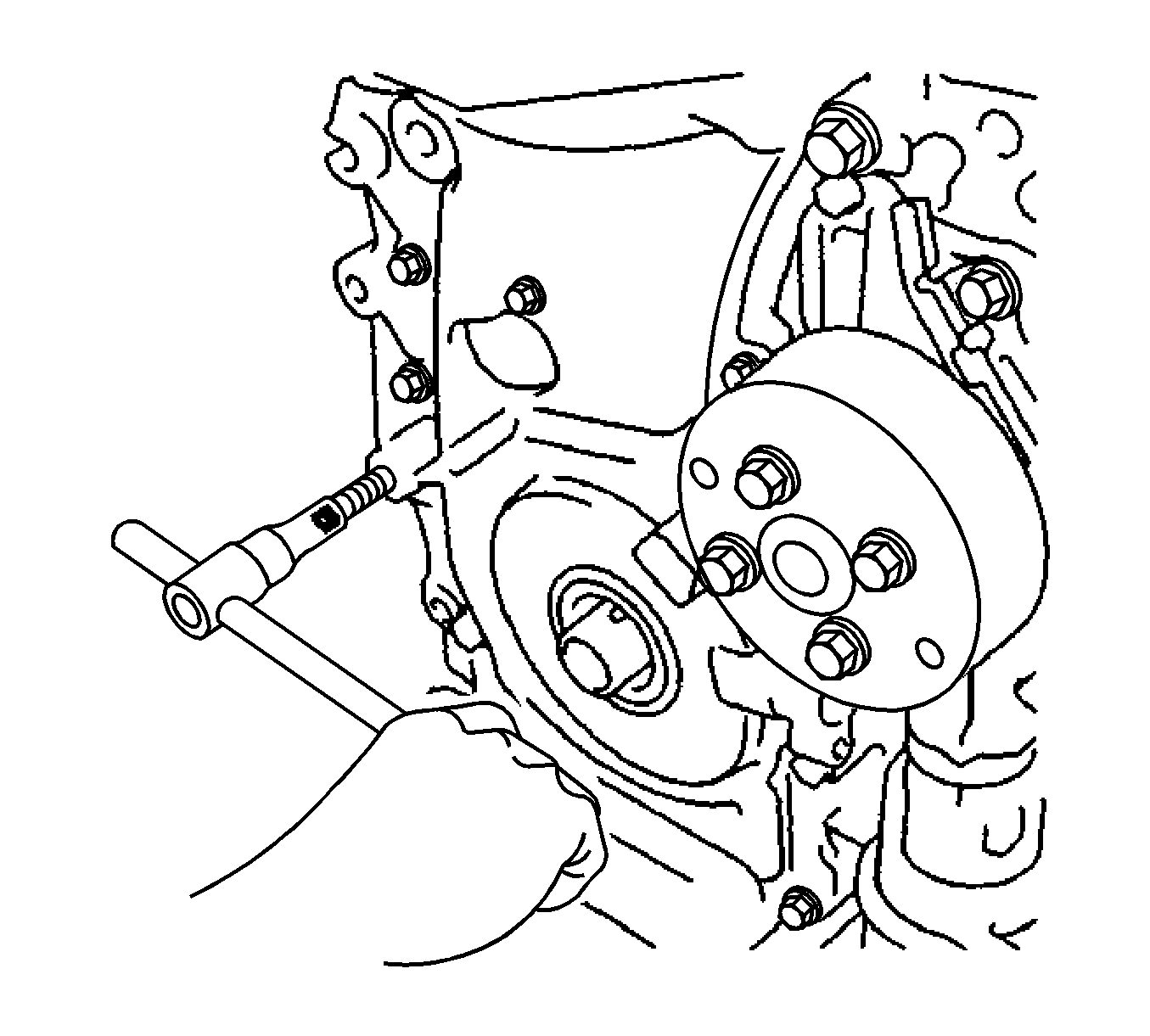
- Using an E10 TORX® socket, remove the stud bolt for the V-ribbed belt tensioner.
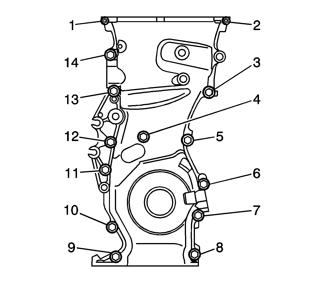
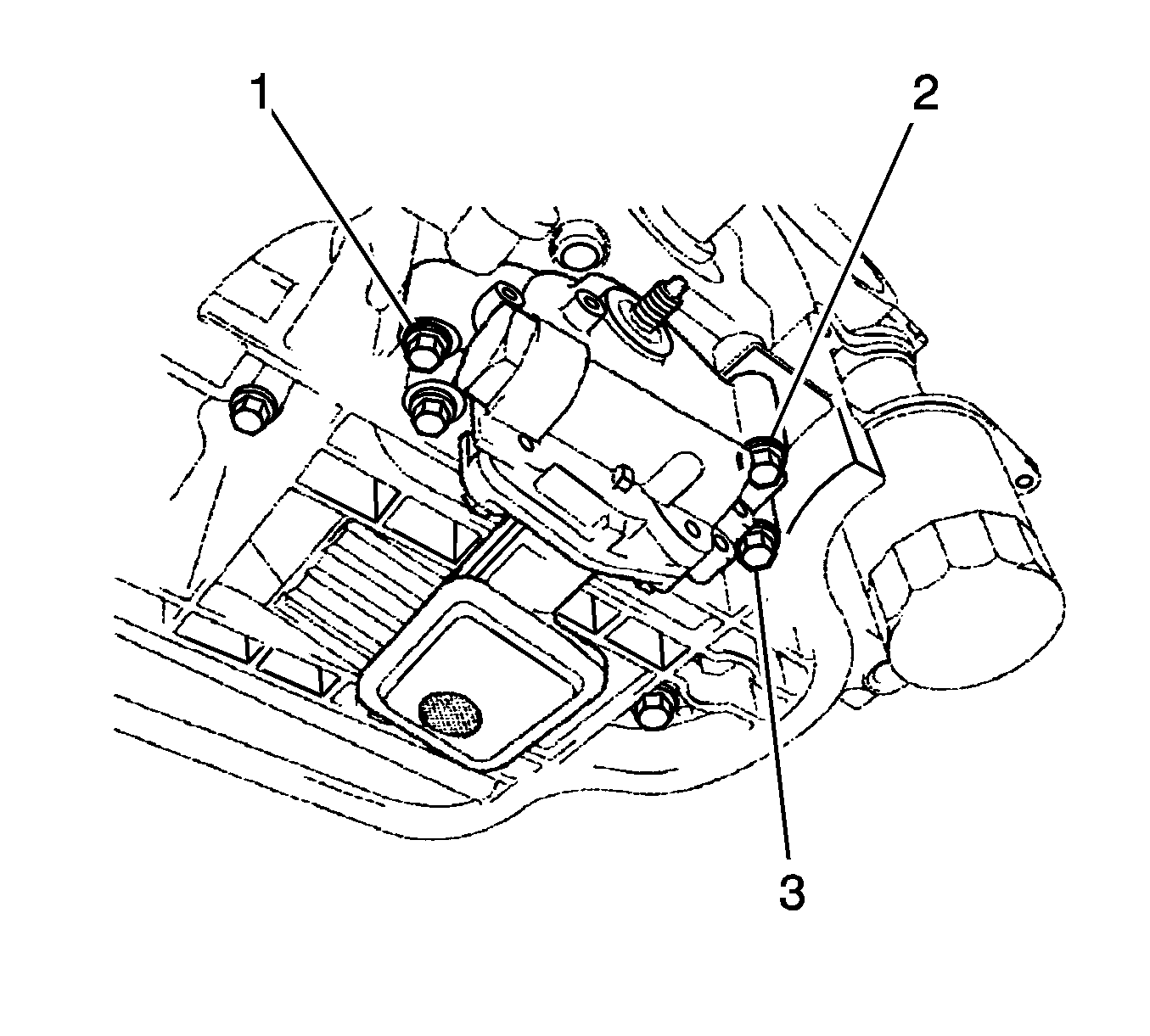
- Remove the 12 bolts (3-14) and 2 nuts (1, 2).
- Remove the timing chain cover by prying the portions between the timing chain cover, cylinder head and cylinder block with a screwdriver.
- Remove the No. 1 crankshaft position sensor plate.
- Remove the timing chain guide.
- Remove the chain tensioner slipper.
- Remove the No. 1 chain vibration damper.
- Remove the chain sub-assembly.
- Remove the crankshaft timing sprocket.
- Remove the No. 2 chain sub-assembly.
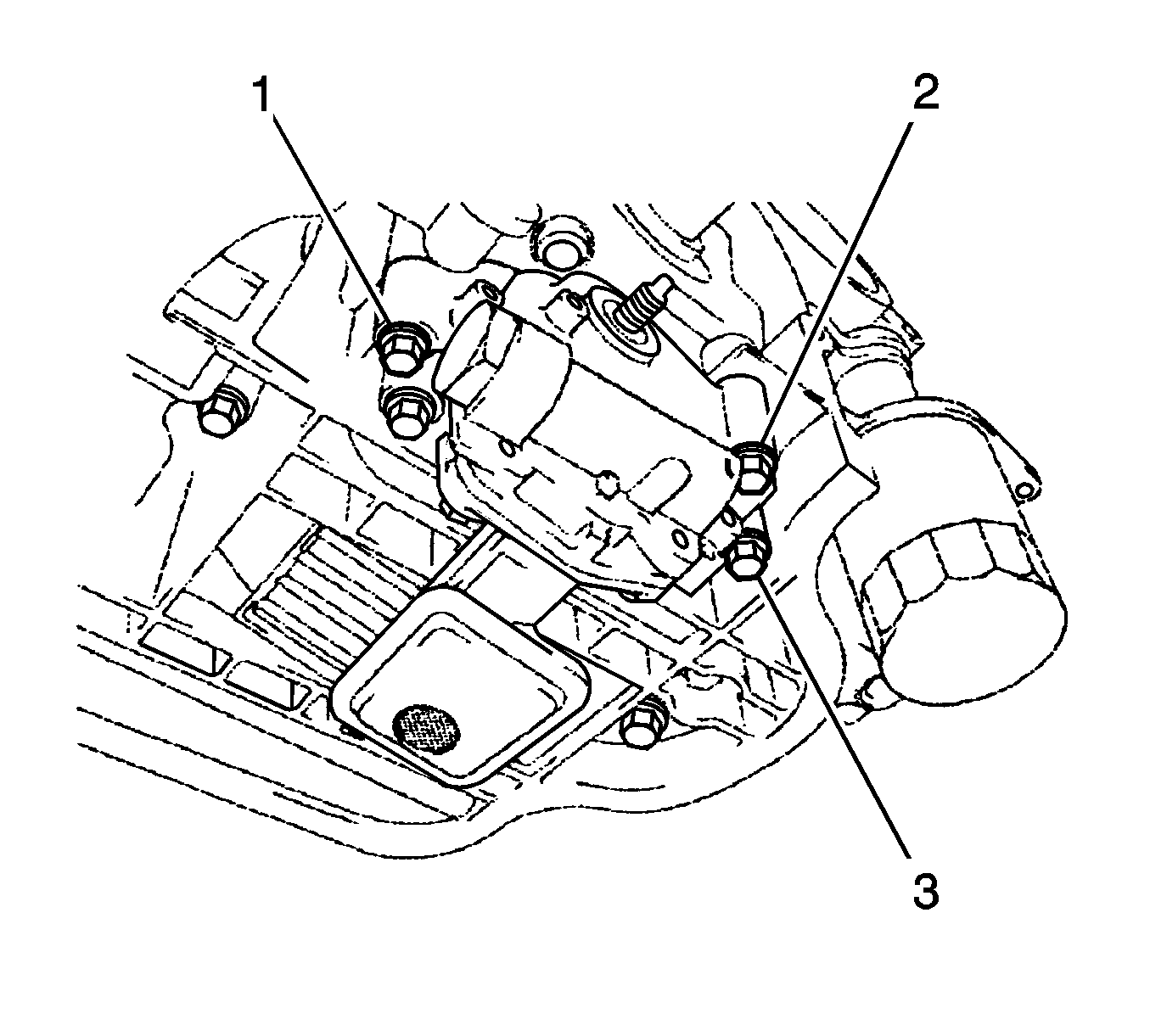
- Remove the 3 bolts (1, 2, 3), oil pump and gasket.
Warning: Refer to Battery Disconnect Warning in the Preface section.
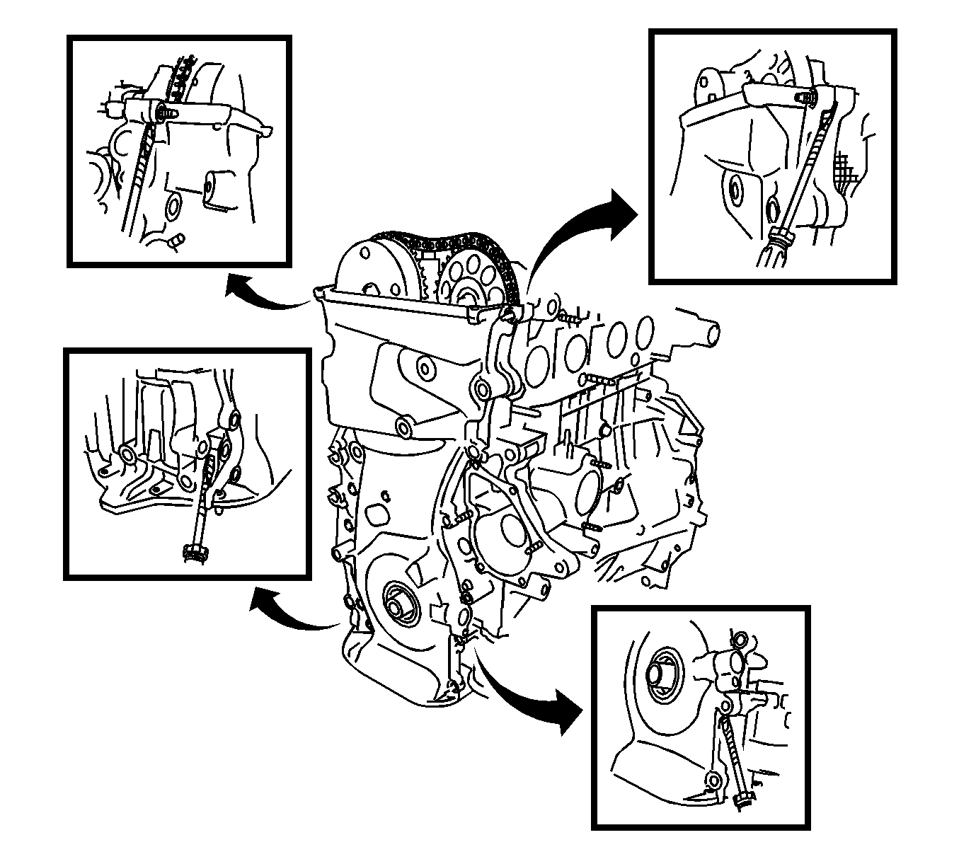
Note: Tape the screwdriver tip before use.
Disassembly Procedure
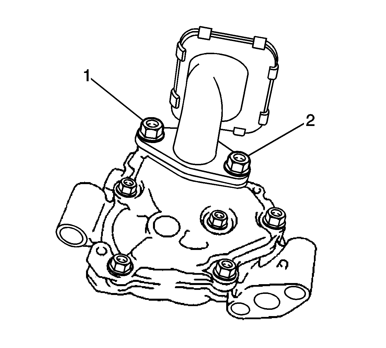
- Remove the 2 nuts (1, 2), oil pump strainer and gasket.
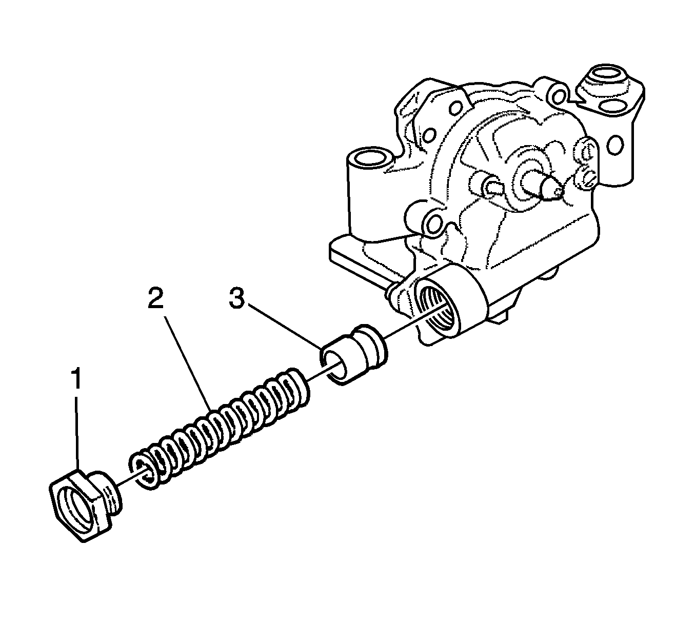
- Using a 27 mm socket wrench, remove the plug (1).
- Remove the valve spring (2) and relief valve (3).
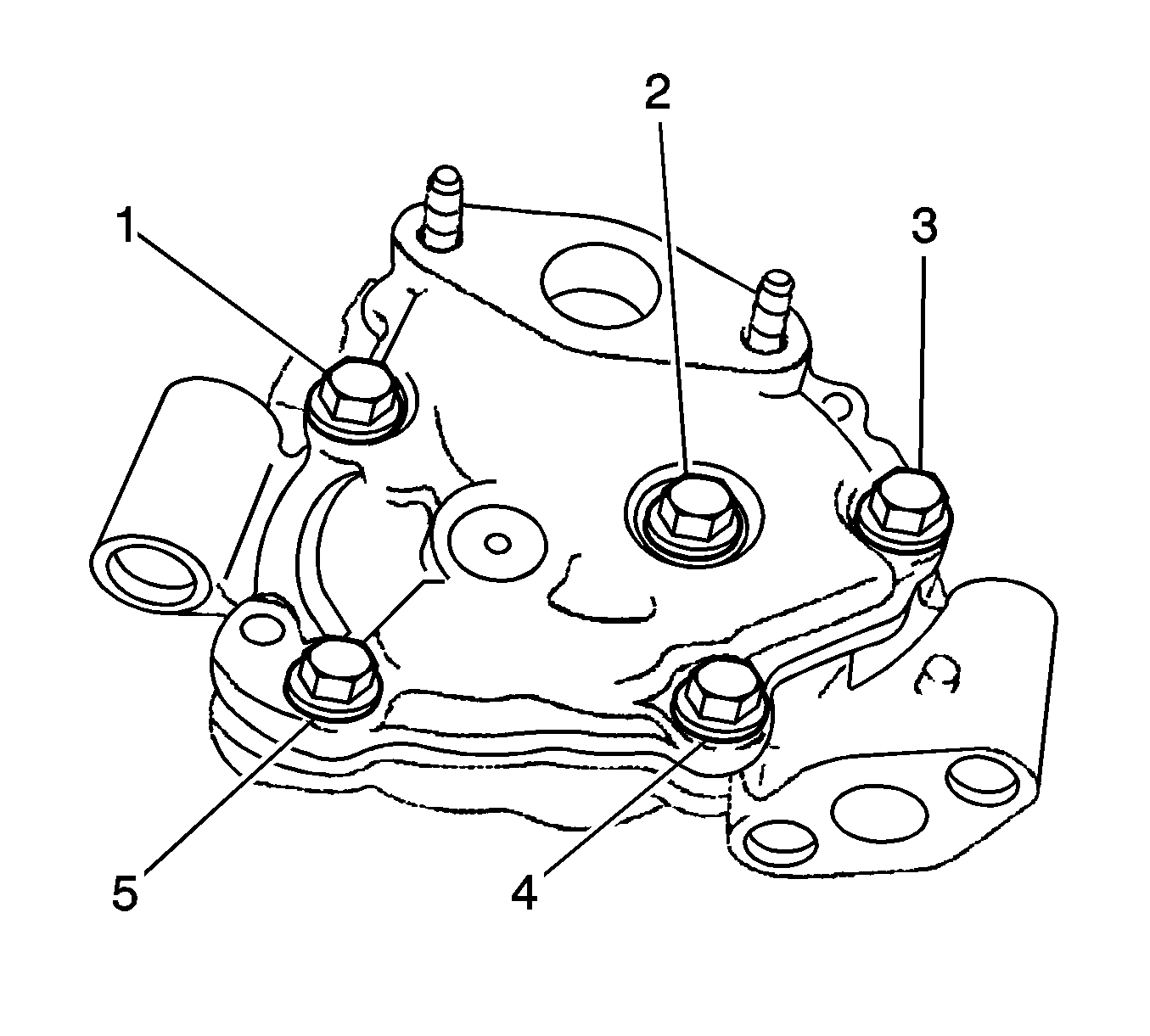
- Remove the 5 bolts (1-5) and oil pump cover.
- Remove the oil pump drive and driven rotors from the oil pump.
Inspection Procedure
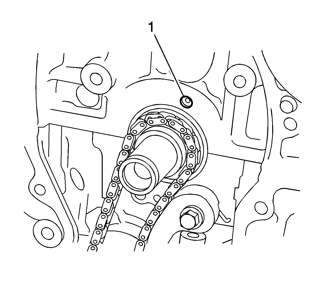
- Check the oil jet (1) for damage or clogging. If necessary, repair the cylinder block.
- Check the relief valve.
- Coat the valve with engine oil, and then check that the valve falls smoothly into the valve hole by its own weight.
- Check the side clearance.
- Using a feeler gauge and precision straightedge, measure the clearance between the rotors and precision straightedge.
- Check the tip clearance.
- Using a feeler gauge (1), measure the clearance between the drive and driven rotor tips.
- Check the body clearance.
- Using a feeler gauge, measure the clearance between the driven rotor and pump body.
- Inspect No. 2 chain sub-assembly.
- Inspect chain tensioner plate.
- Measure the chain tensioner plate wear.
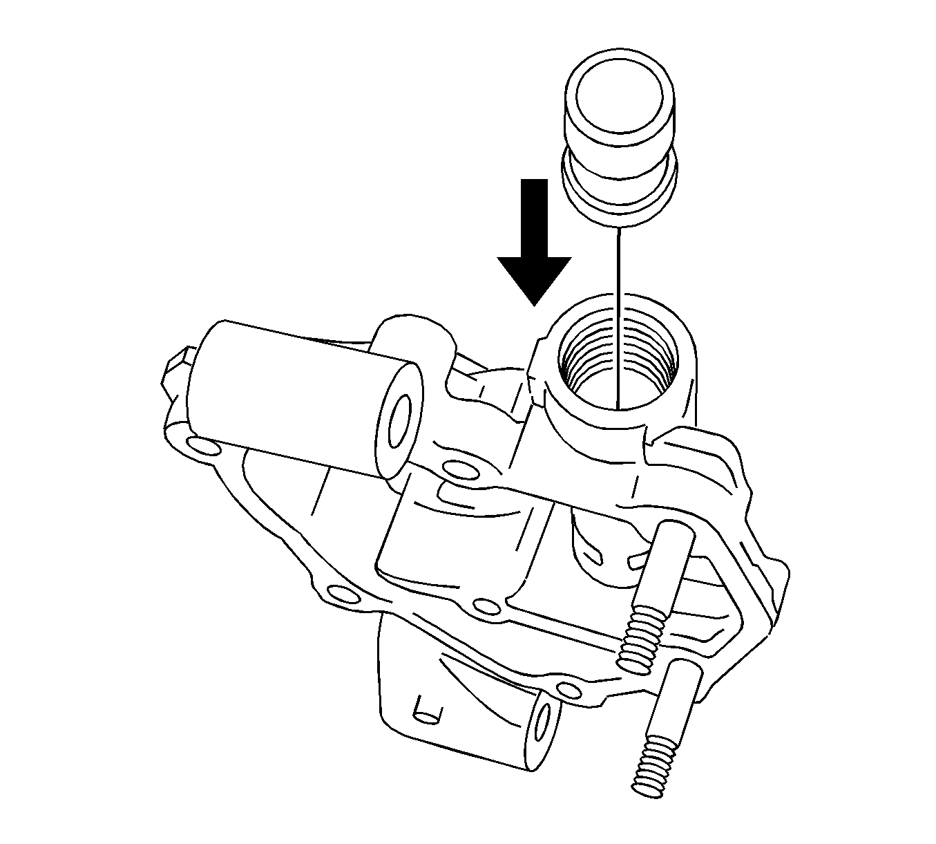
If it does not, replace the relief valve. If necessary, replace the oil pump assembly.
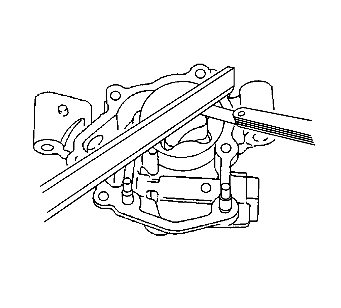
If the side clearance is greater than the maximum, replace the oil pump assembly.
Specification
| • | Standard Clearance: 0.030 to 0.085 mm (0.0012 to 0.0034 in.) |
| • | Maximum Clearance: 0.160 mm (0.0063 in.) |
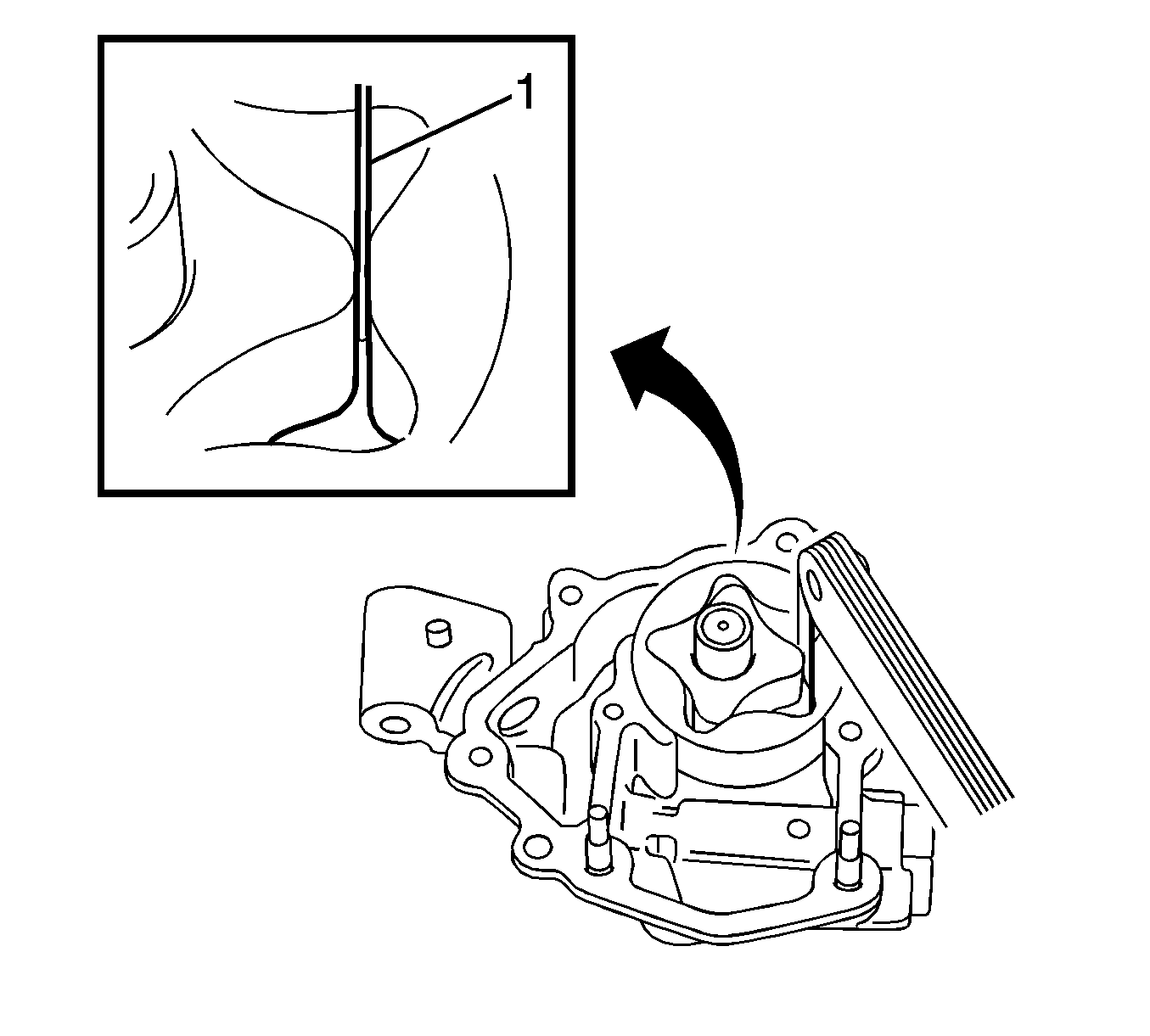
If the tip clearance is greater than the maximum, replace the oil pump assembly.
Specification
| • | Standard Clearance: 0.080-0.160 mm (0.0031-0.0063 in) |
| • | Maximum Clearance: 0.35 mm (0.0138 in) |
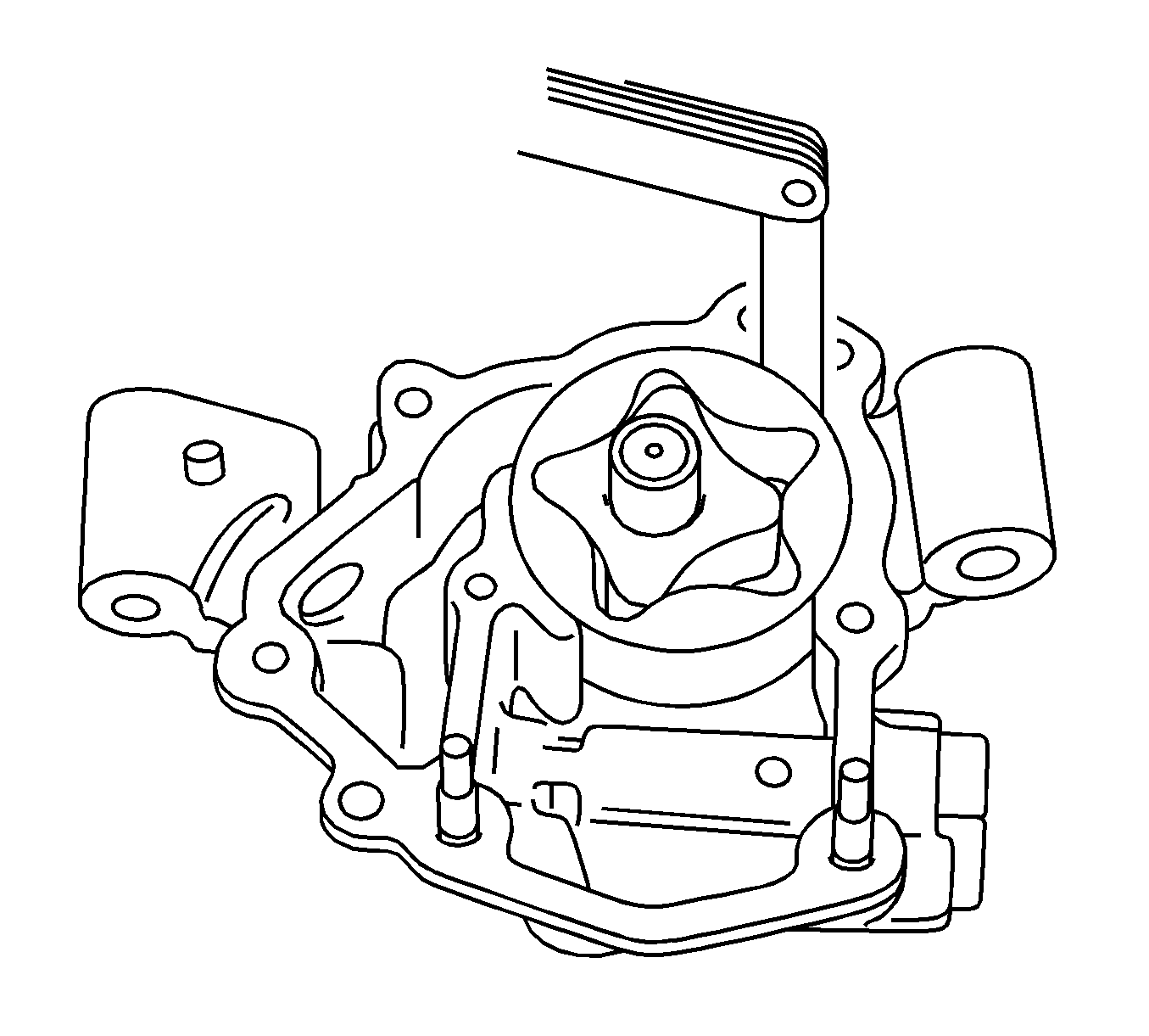
If the body clearance is greater than the maximum, replace the oil pump assembly.
Specification
| • | Standard Clearance: 0.100-0 0.170 mm (0.0039-0.0067 in) |
| • | Maximum Clearance: 0.325 mm (0.0128 in) |
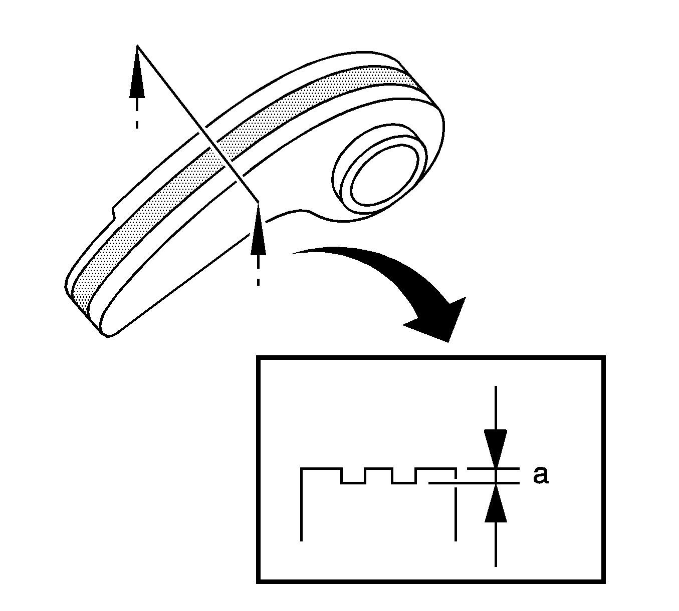
If the wear (a) is greater than the maximum, replace the chain tensioner plate.
Specification
Maximum wear: 0.5 mm (0.020 in.)
Reassembly Procedure
- Coat the drive rotor and driven rotor with engine oil.
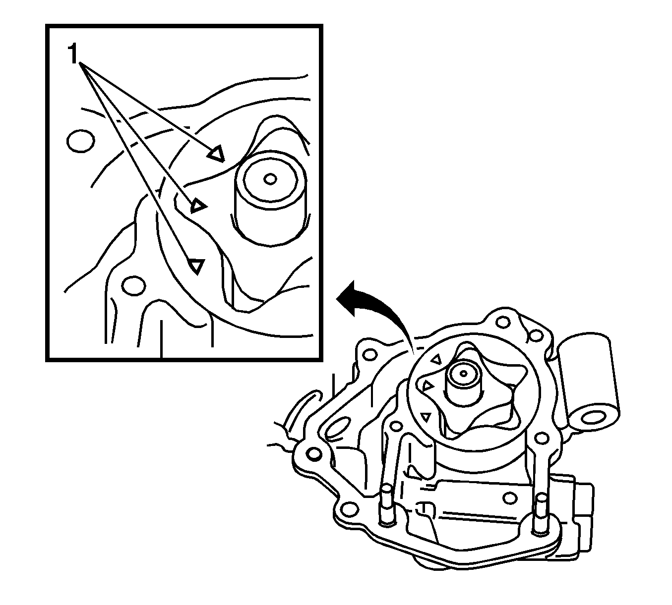
- Place the drive and driven rotors into the oil pump with the marks (1) facing the pump cover side.
- Install the oil pump cover with the 5 bolts (1-5) and tighten to 8.8 N·m (78 lb in).
- Coat the relief valve with engine oil.
- Insert the relief valve (3) and spring (2) into the pump body hole.
- Using a 27 mm socket wrench, install the plug (1) and tighten to 49 N·m (36 lb ft).
- Install a new gasket and the oil strainer with the 2 nuts (1, 2) and tighten to 8.8 N·m (78 lb in).
Caution: Refer to Fastener Caution in the Preface section.


Installation Procedure
- Install a new gasket and the oil pump with the 3 bolts (1, 2, 3) and tighten to 19 N·m (14 lb ft).
- Install the No. 2 chain sub-assembly.
- Install the crankshaft timing sprocket.
- Install the No. 1 chain vibration damper.
- Install the chain sub-assembly.
- Install the chain tensioner slipper.
- Install the timing chain guide.
- Install the crankshaft position sensor plate.
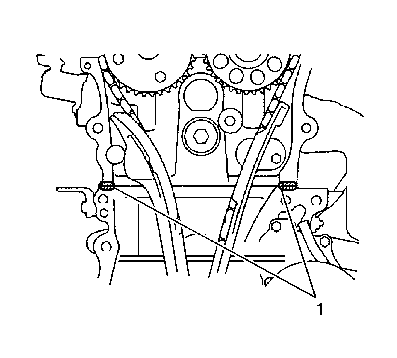
- Remove any old sealing material and be careful not to drop any oil on the contact surfaces of the timing chain cover, cylinder head and cylinder block.
- Apply Three Bond 1217B, or equivalent, GM part number 12378521 (Canadian part number 88901148) to the timing chain cover.
- Install the timing chain cover with the 12 bolts (2, 3, 4) and 2 nuts (1) and tighten.
- Using an E10 TORX® socket, install the stud bolt for the V-ribbed belt tensioner and tighten to 22 N·m (16 lb ft).
- Install the chain tensioner assembly.
- Install the v-ribbed belt tensioner assembly.
- Install the transverse engine mounting bracket.
- Install the crankshaft pulley.
- Install the oil pan.
- Install the crankshaft position sensor.
- Install the idler pulley.
- Install the right engine mount.
- Install the exhaust manifold converter. Refer to Exhaust Manifold Replacement.
- Install the intake manifold insulator.
- Install the intake manifold. Refer to Intake Manifold Replacement.
- Install the camshaft timing oil control valve assembly.
- Install the fuel delivery pipe sub-assembly.
- Connect the fuel main tube.
- Install the engine oil level dipstick guide.
- Install the engine oil level dipstick.
- Install the cylinder head cover. Refer to Camshaft Cover Replacement.
- Install the spark plug. Refer to Spark Plug Replacement.
- Install the ignition coil assembly. Refer to Ignition Coil Replacement.
- Install the throttle body assembly.
- Install the air cleaner cap with hose.
- Install the radiator reserve tank assembly.
- Connect the inlet heater water hose.
- Connect the outlet heater water hose.
- Install the radiator hose.
- Install the generator assembly. Refer to Generator Replacement.
- Install the v-ribbed belt. Refer to Drive Belt Replacement.
- Install the front exhaust pipe assembly. Refer to Front Pipe Replacement.
- Install the catalytic converter assembly. Refer to Catalytic Converter Replacement.
- Connect the cable to negative battery terminal.
- Add the engine oil. Refer to Engine Oil and Oil Filter Replacement.
- Add the engine coolant. Refer to Cooling System Draining and Filling.
- Inspect the fuel leak.
- Inspect the coolant leak.
- Inspect the oil leak.
- Inspect the exhaust gas leak.
- Inspect the ignition timing.
- Inspect the engine idle speed.
- Install the suspension tower damper assembly (with front strut bar).
- Install the outer cowl top panel.
- Install the windshield wiper motor and link assembly. Refer to Windshield Wiper Motor Replacement
- Install the engine cover. Refer to Engine Cover Replacement.
- Install the left engine under cover.
- Install the right engine under cover.
- Install the right front wheel.
Note:
• Remove any oil from the contact surfaces. • Install the chain cover within 3 minutes of applying sealant. • Do not add engine oil for at least 2 hours after installing the chain cover.
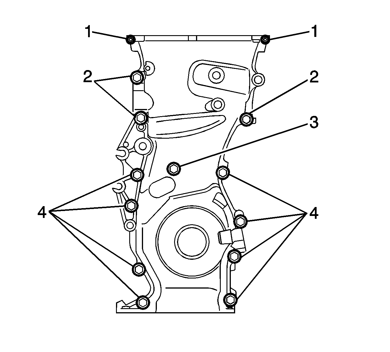
| • | Bolt 3 to 9.0 N·m (80 lb in). |
| • | Bolts 4 to 25 N·m (18 lb ft). |
| • | Bolts 2 to 55 N·m (41 lb ft). |
| • | Nuts 1 to 11 N·m (8 lb ft). |
