Special Tools
J-8614-A Pinion Flange Holder and Remover
Removal Procedure
- Discharge the fuel system pressure. Refer to
Fuel Pressure Relief.
- Disconnect the cable from the negative battery terminal. Refer to
Battery Negative Cable Disconnection and Connection.
- Remove the windshield wiper motor and link assembly. Refer to
Windshield Wiper Motor Replacement.
- Remove the outer cowl top panel.
- Remove the suspension tower damper assembly with front strut bar.
- Remove the right front wheel.
- Remove the left engine under cover.
- Remove the right engine under cover.
- Remove the engine cover. Refer to
Engine Cover Replacement.
- Drain the engine coolant. Refer to
Cooling System Draining and Filling.
- Drain the engine oil. Refer to
Engine Oil and Oil Filter Replacement.
- Remove the catalytic converter. Refer to
Catalytic Converter Replacement.
- Remove the front exhaust pipe assembly. Refer to
Front Pipe Replacement.
- Remove the V-ribbed belt. Refer to
Drive Belt Replacement.
- Remove the generator assembly. Refer to
Generator Replacement.
- Separate the radiator reserve tank assembly.
- Remove the air cleaner with hose.
- Remove the throttle body assembly.
- Remove the ignition coil assembly. Refer to
Ignition Coil Replacement.
- Remove the spark plug. Refer to
Spark Plug Replacement.
- Remove the cylinder head cover. Refer to
Camshaft Cover Replacement.
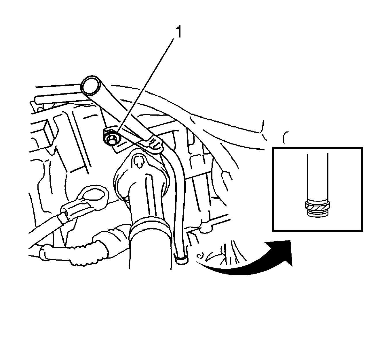
- Remove the bolt (1) and engine oil level dipstick guide.
- Remove the O-ring from the engine oil level dipstick guide.
- Remove the engine oil level dipstick guide.
- Disconnect the fuel main tube.
- Remove the fuel delivery pipe.
- Remove the camshaft timing oil control valve assembly.
- Remove the intake manifold. Refer to
Intake Manifold Replacement.
- Remove the exhaust manifold heat insulator.
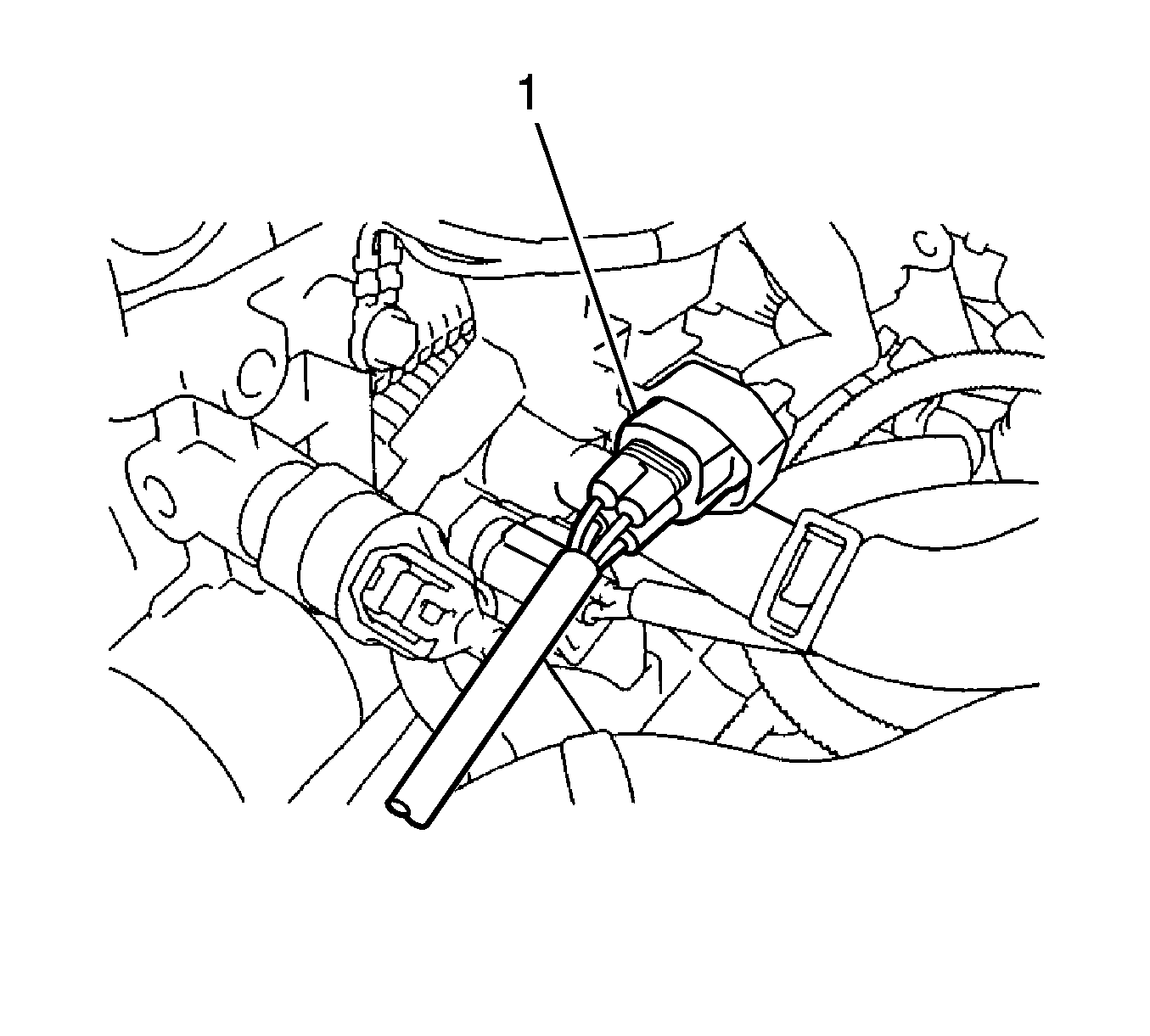
- Disconnect the air-fuel ratio sensor connector (1).
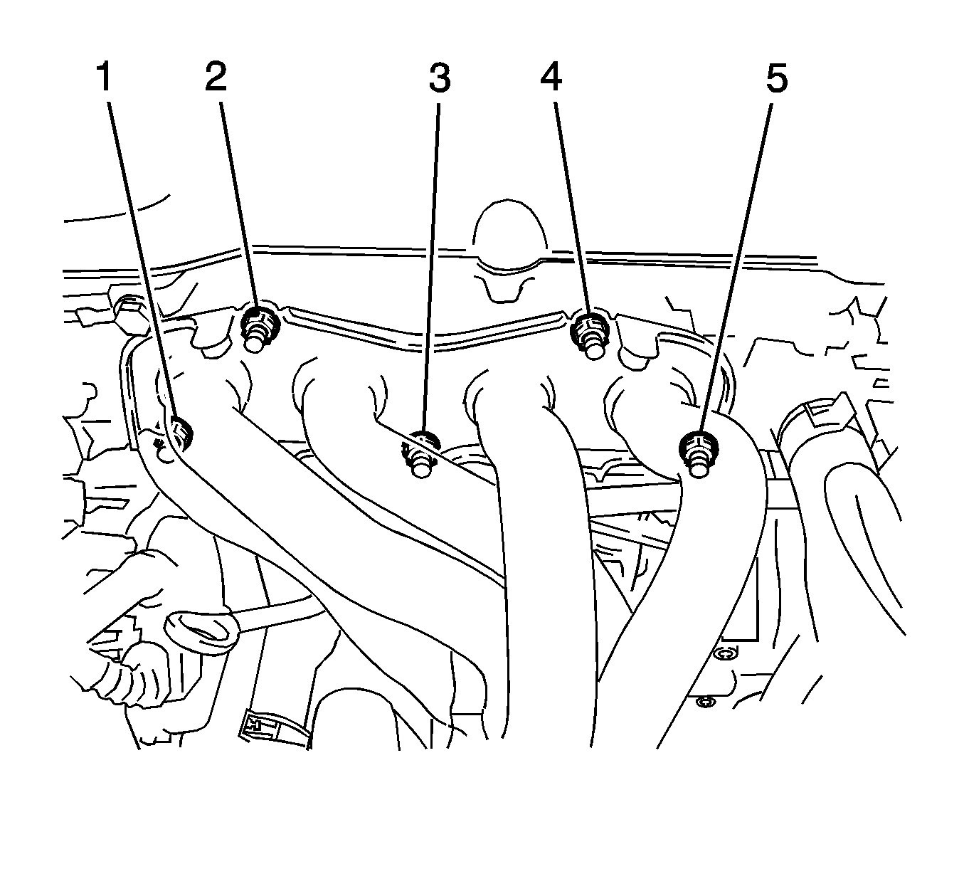
- Remove the 5 nuts (1-5), exhaust manifold converter, and gasket.
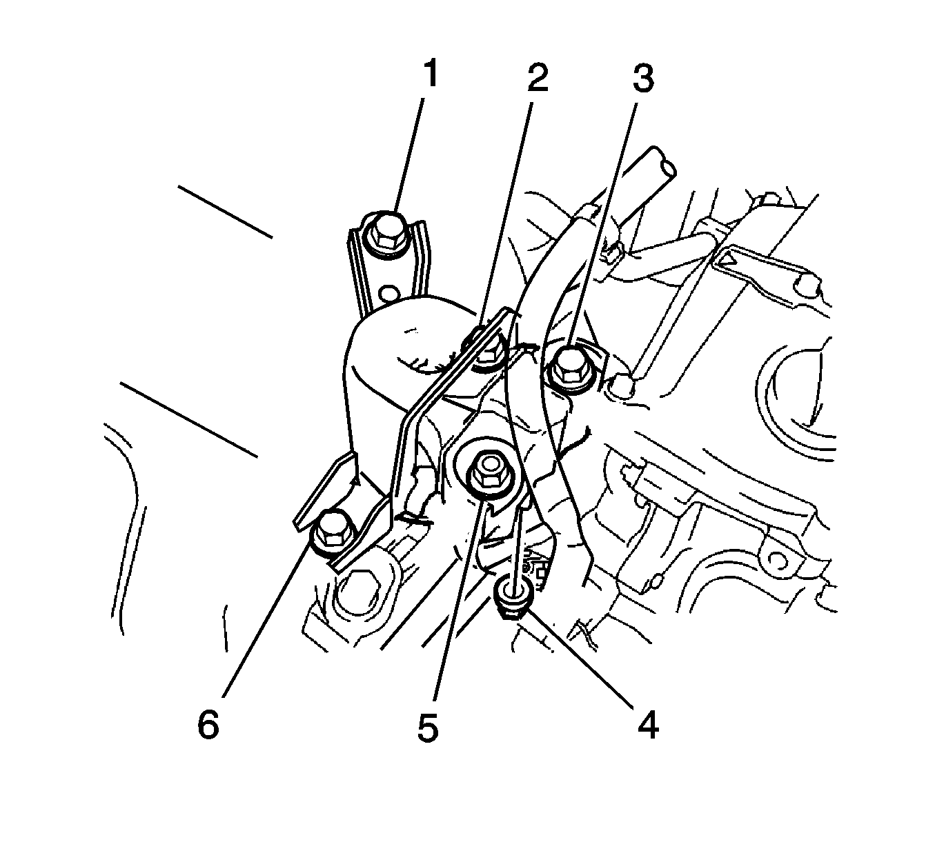
Note: Do not apply excessive force to the return tube when removing the right engine mounting insulator sub-assembly.
Note: Keep clearance by lowering the engine using the engine support fixture when removing the front engine mounting insulator.
- Install the engine support fixture. Refer to
Engine Support Fixture.
- Remove the 4 bolts (1, 2, 3, 6) and 2 nuts (4, 5), then remove the right engine mounting insulator.
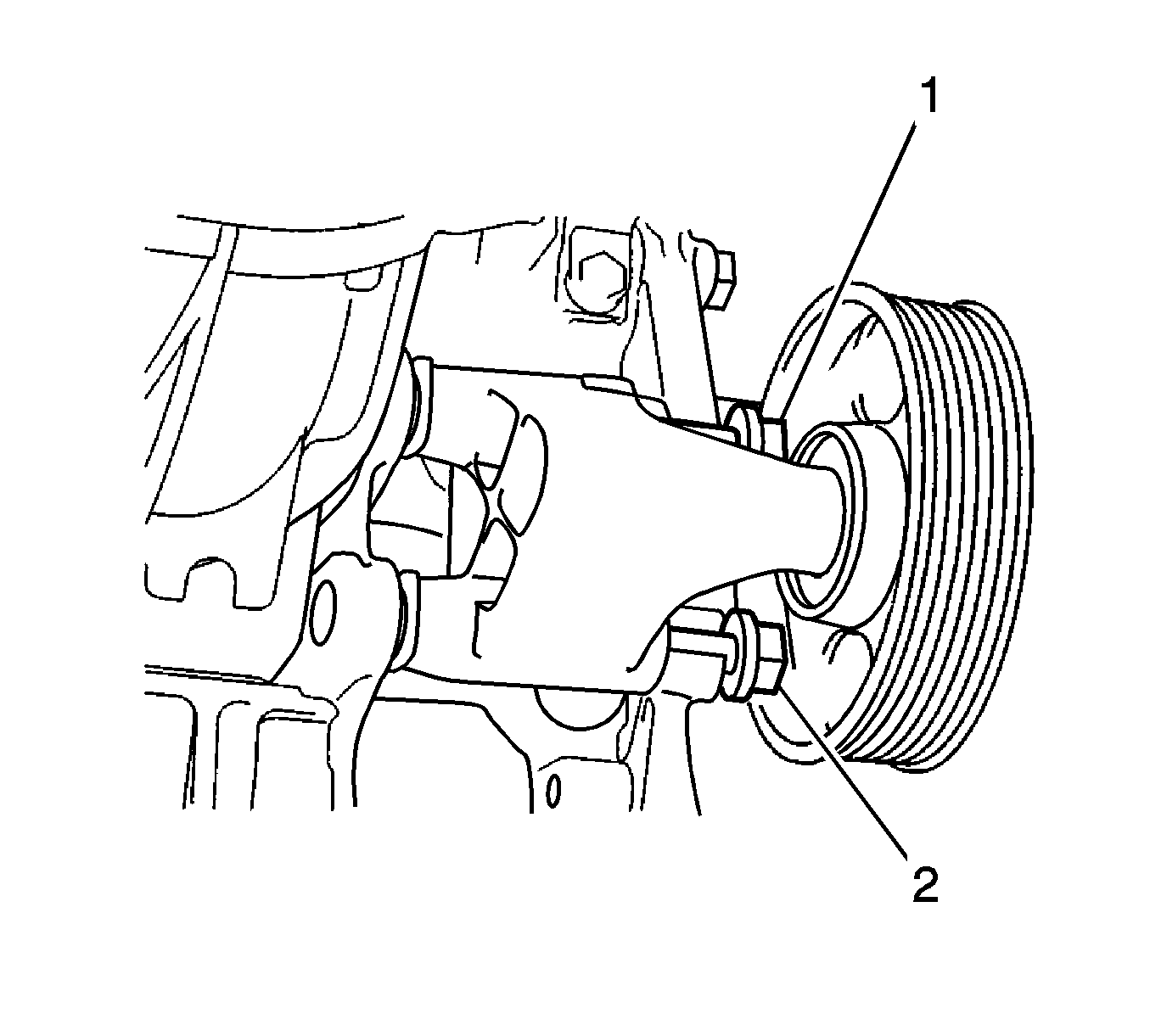
- Loosen the 2 bolts (1, 2) and remove the idler pulley.
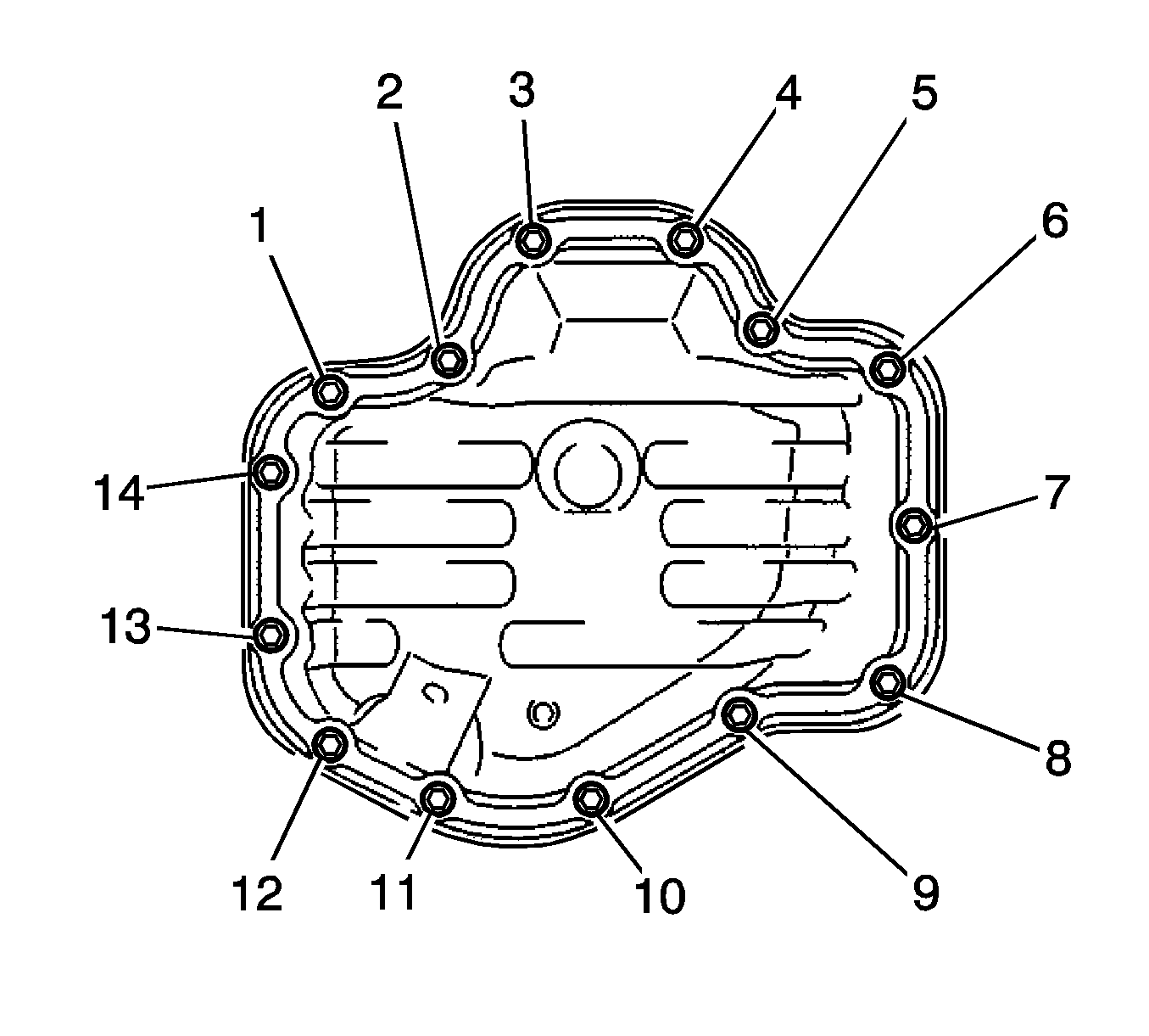
- Remove the 12 bolts (2-11) and 2 nuts (1, 12).
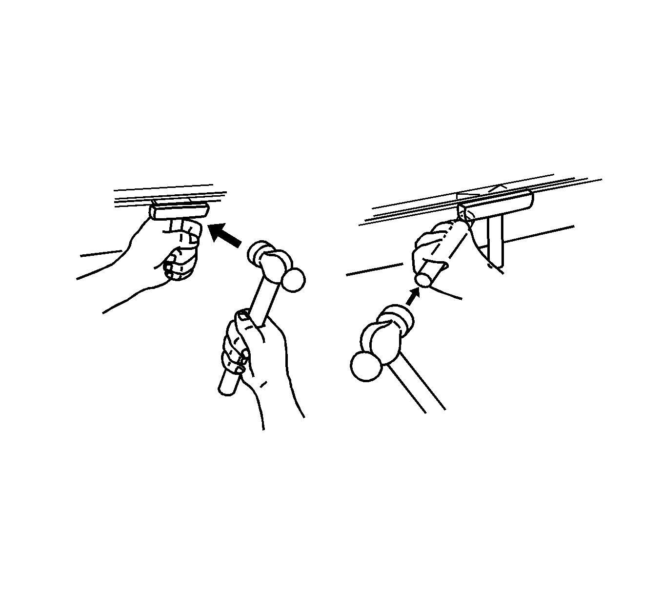
Note: Be careful not to damage the contact surface of the crankcase, chain cover or oil pan.
- Insert the blade of oil pan seal cutter between the crankcase, chain cover and oil pan, then cut through the applied sealer and remove the oil pan.
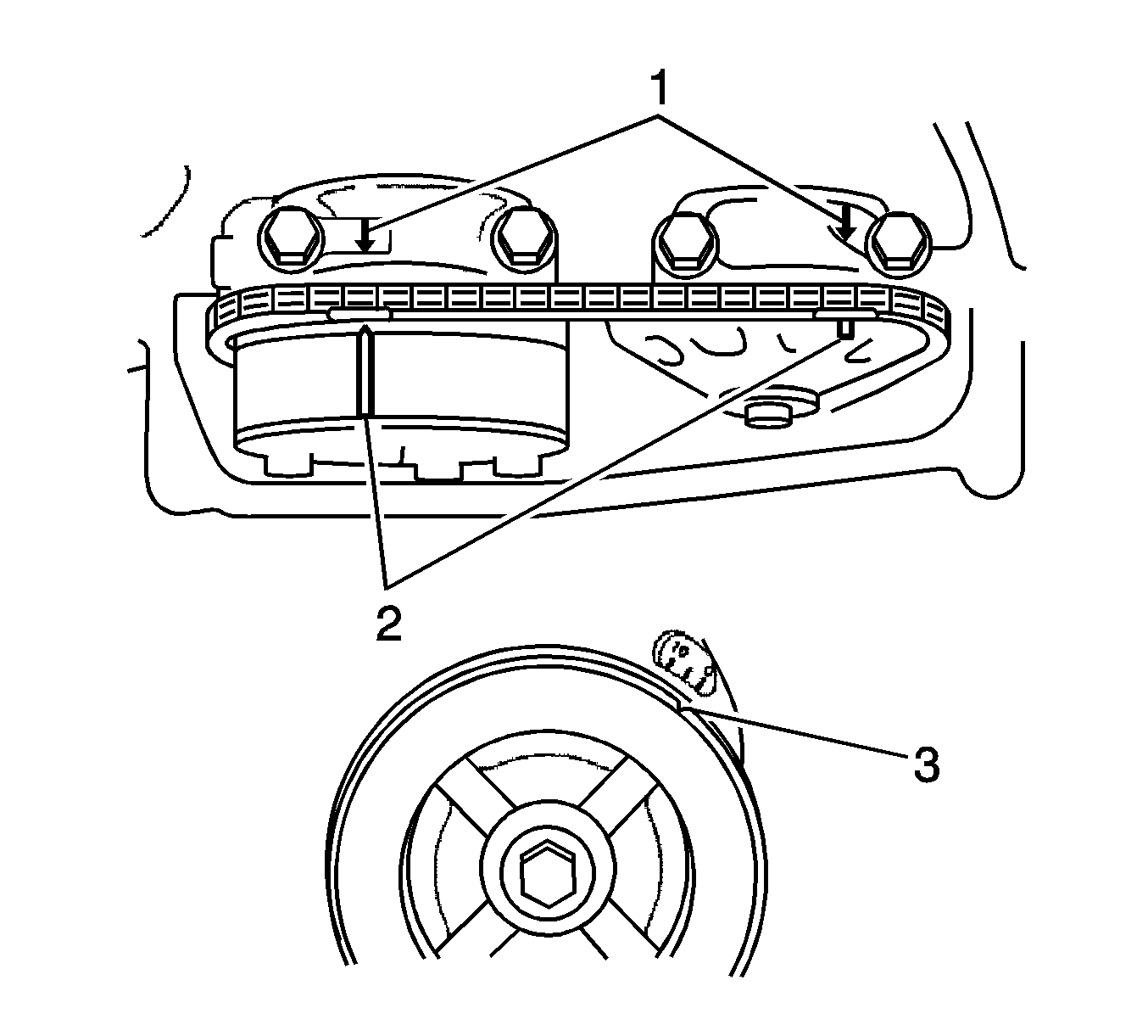
- Set No. 1 cylinder to TDC/compression.
| • | Turn the crankshaft pulley until the groove (3) and the timing mark 0 on the timing chain cover are aligned. |
| • | Check that each timing mark (2) on the camshaft timing gear and sprocket is aligned with the timing marks located on the camshaft bearing caps (1) as shown in the illustration. If not, turn the crankshaft by 1 revolution (360°)
to align the timing marks as above. |
- Remove the crankshaft pulley.
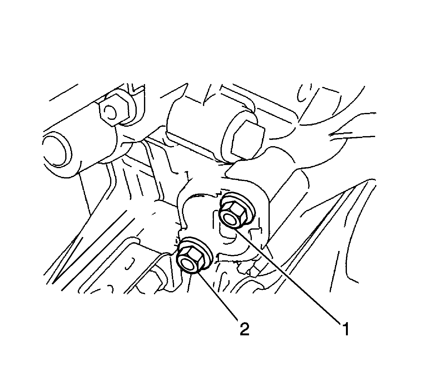
Note: Do not turn the crankshaft without the chain tensioner assembly installed.
- Remove the 2 nuts (1, 2) and the chain tensioner assembly, and gasket.
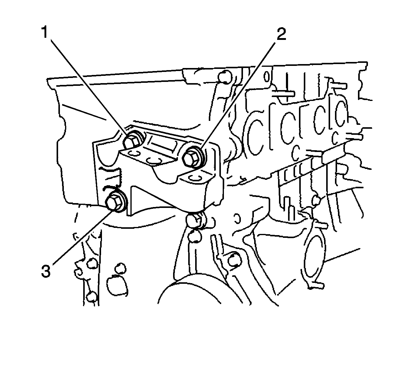
- Remove the 3 bolts (1, 2, 3) and transverse engine mounting bracket.
Note: Do not lift the engine more than necessary.
- Lift the engine upward.
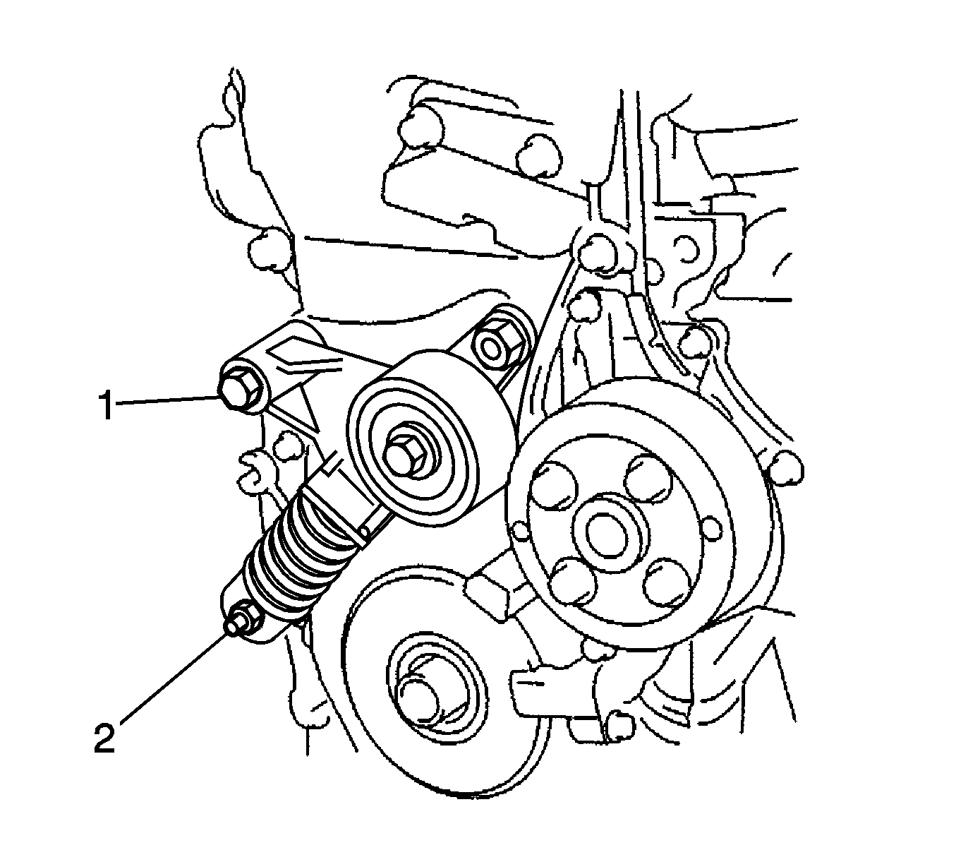
- Remove the bolt (1), nut (2) and V-ribbed belt tensioner assembly.
- Remove the crankshaft position sensor.
- Remove the timing chain cover assembly. Refer to
Timing Chain Housing Removal.
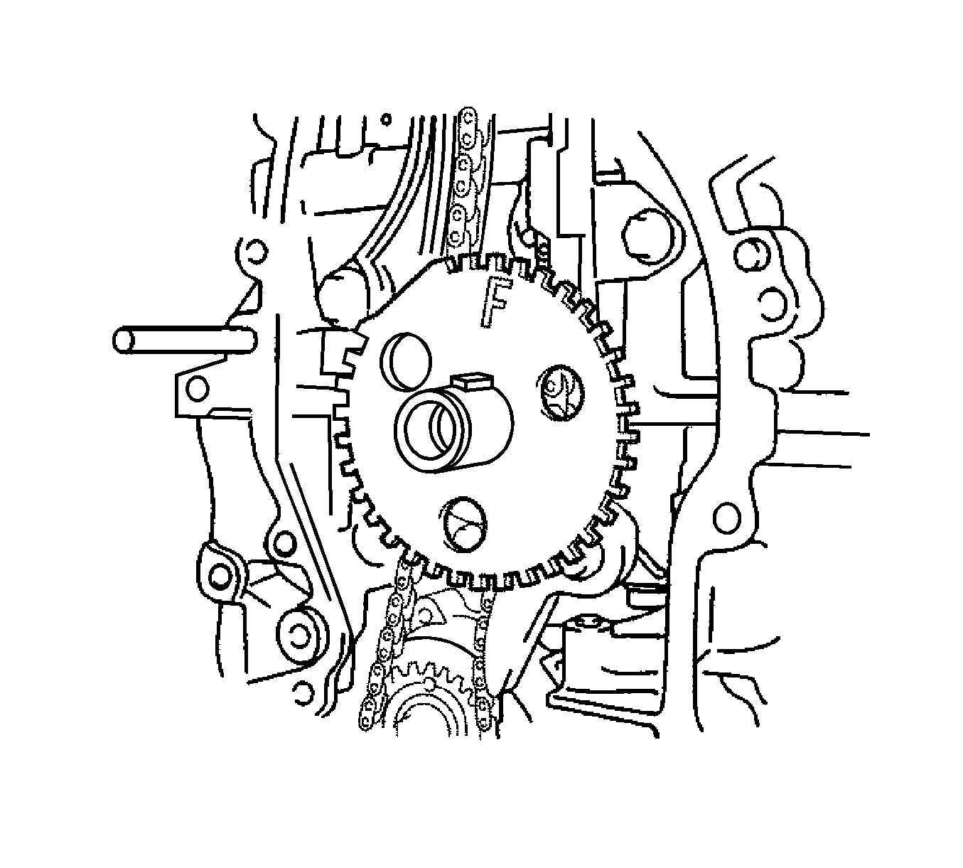
- Remove the crankshaft position sensor plate.
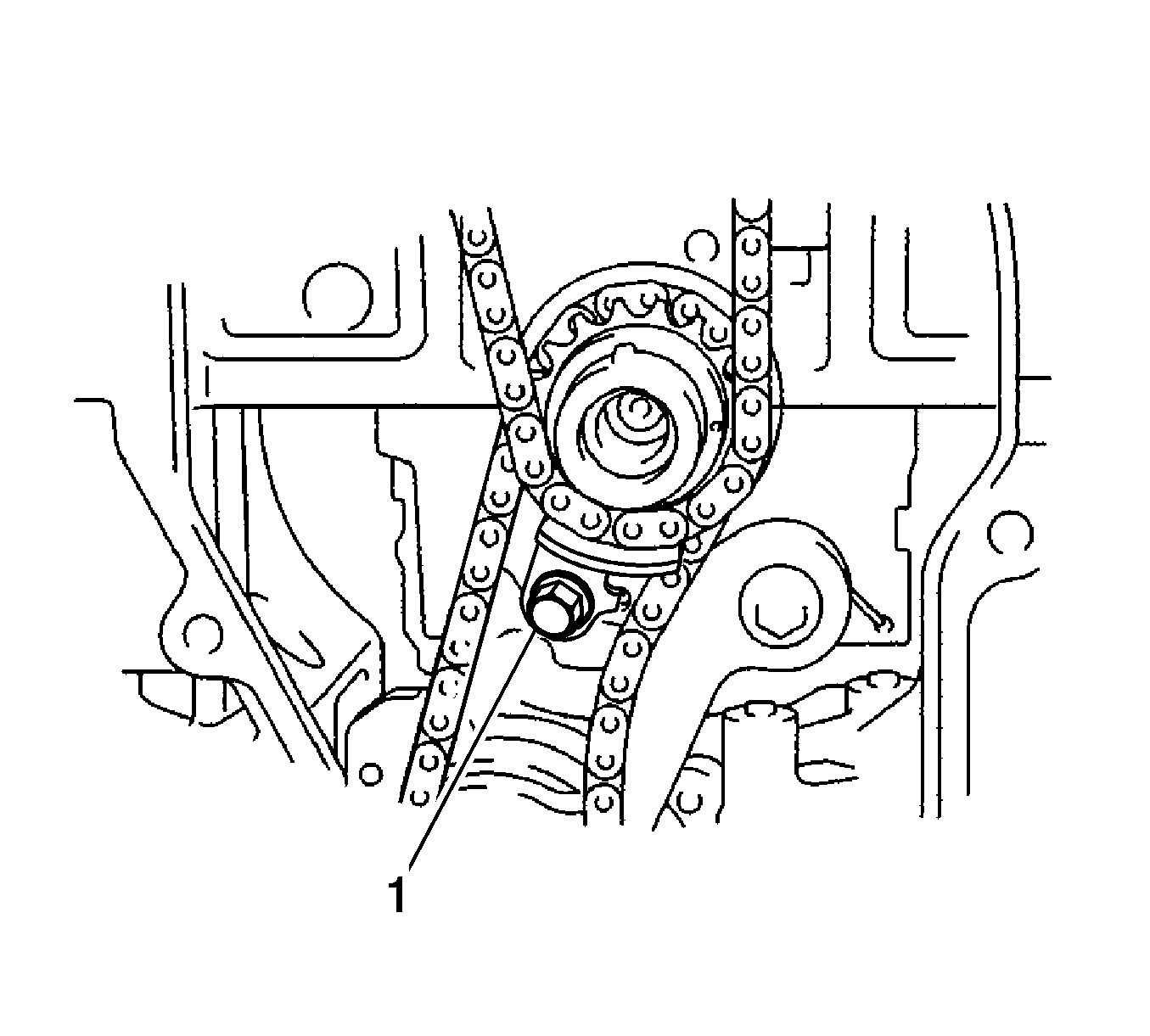
- Remove the bolt (1) and timing chain guide.
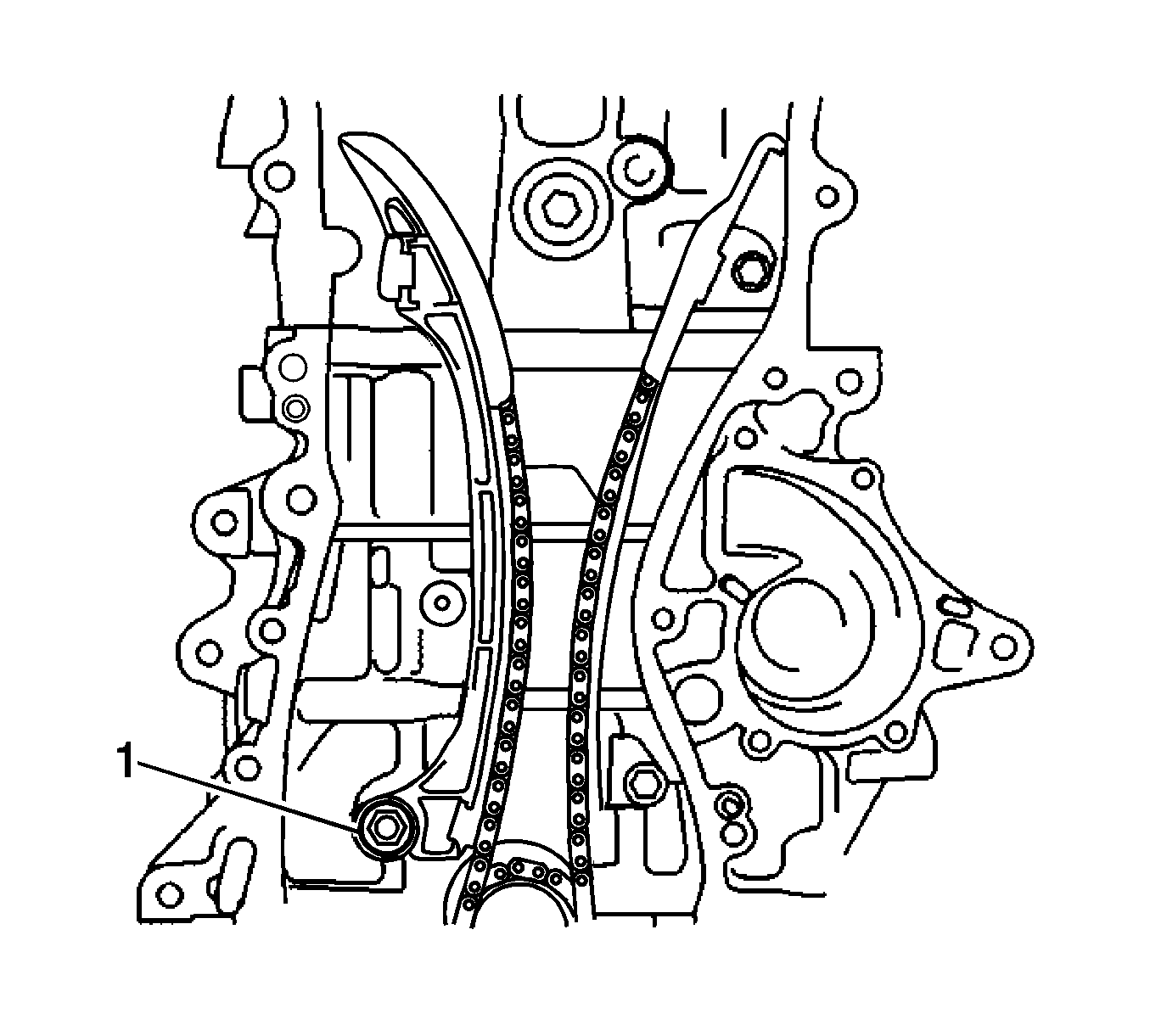
- Remove the bolt (1) and chain tensioner slipper.
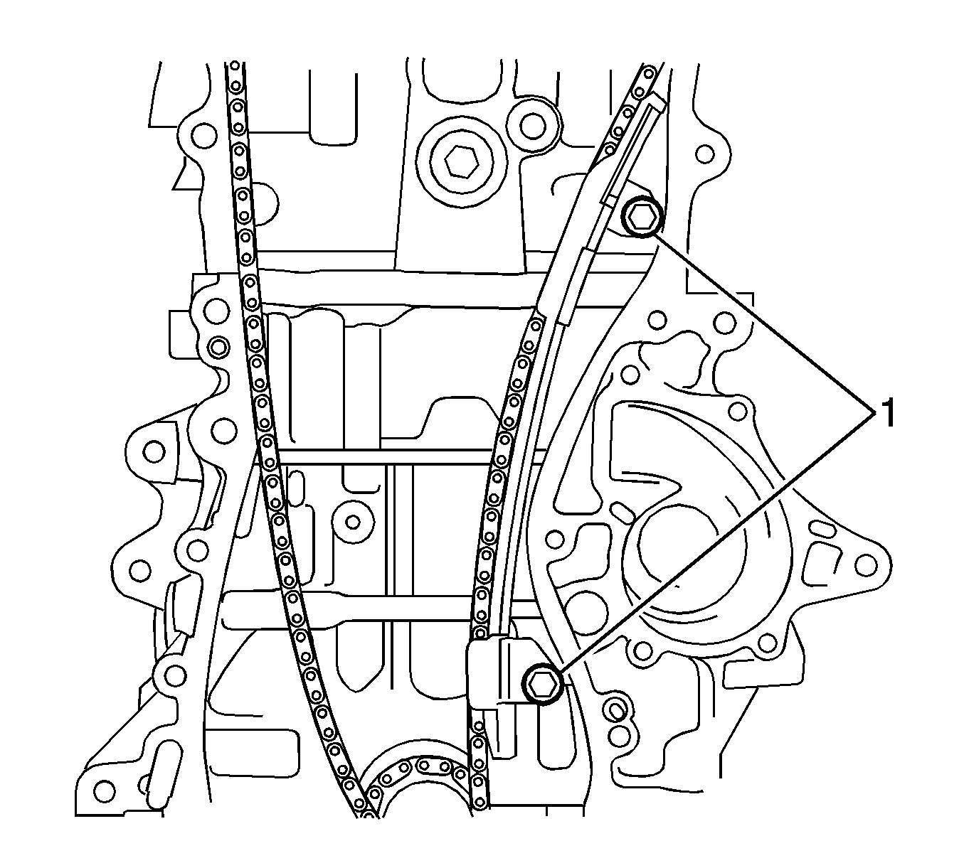
- Remove the 2 bolts (1) and the chain vibration damper.
- Remove the chain sub-assembly.
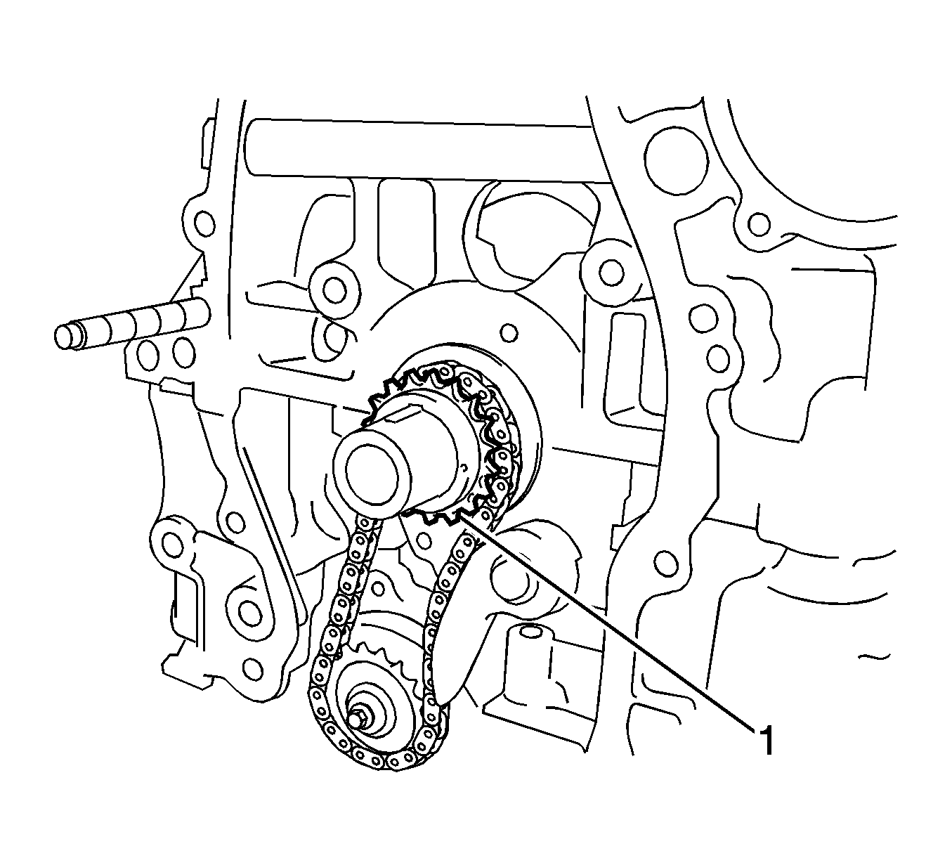
- Remove the crankshaft timing gear (1) from the crankshaft.
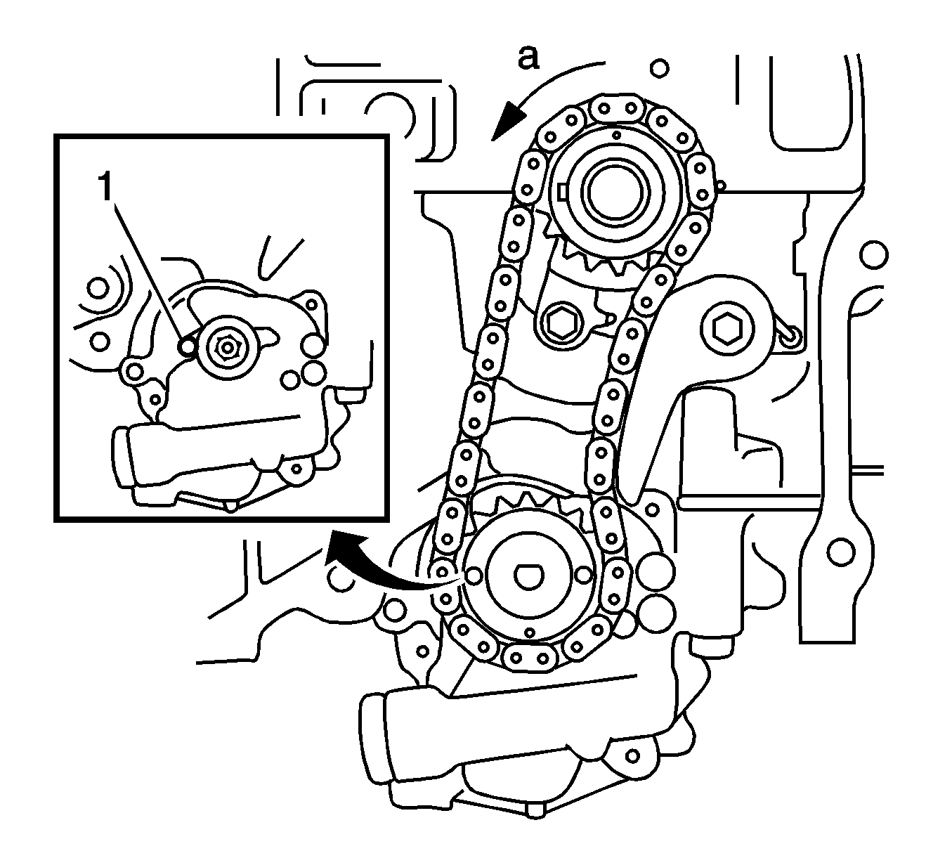
- Turn the crankshaft 90 degrees counterclockwise to align the adjusting hole (1) on the oil pump drive shaft sprocket with the groove on the oil pump.
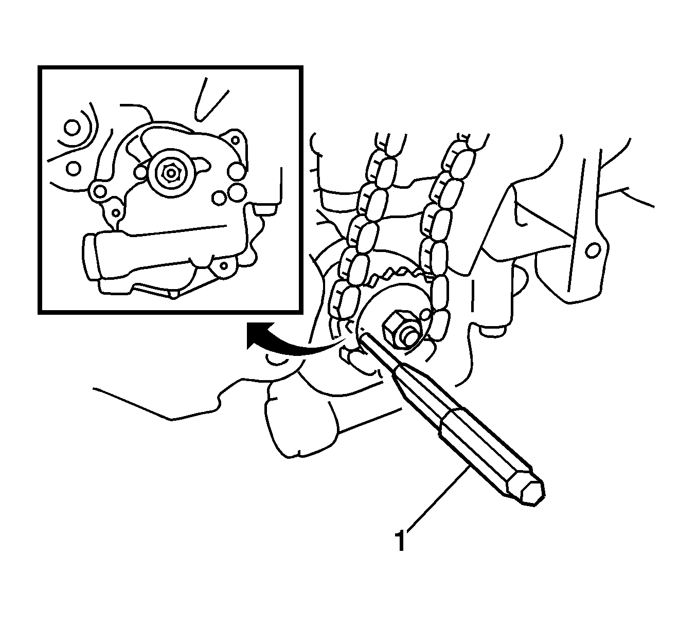
- Insert a 4 mm diameter bar (1) into the adjusting hole of the oil pump drive shaft sprocket to lock the gear in position, and then remove
the nut.
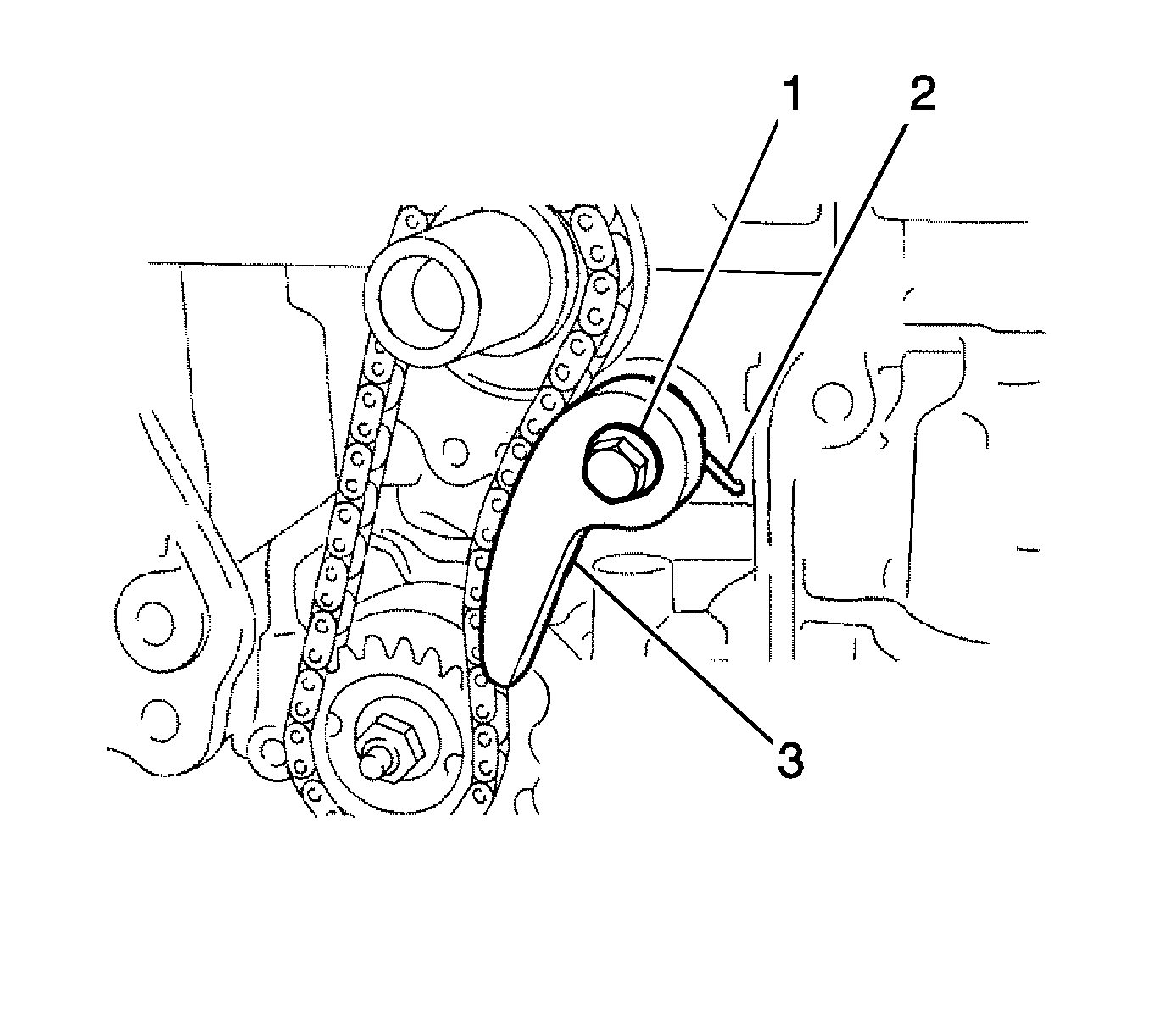
- Remove the bolt (1), chain tensioner plate (3) and spring (2).
- Remove the oil pump drive sprocket, oil pump drive shaft sprocket and oil pump drive chain.
- Disconnect the No. 1 radiator hose.
- Disconnect the outlet heater water hose.
- Disconnect the inlet heater water hose.
- Disconnect the engine wiring as follows:
| 58.1. | Disconnect the radio setting condenser connector. |
| 58.2. | Disconnect the engine oil pressure switch connector. |
| 58.3. | Disconnect the engine coolant temperature sensor connector. |
| 58.4. | Disconnect the camshaft position sensor connector. |
| 58.5. | Remove the bolt and ground cable. |
- Remove the intake camshaft. Refer to
Intake Camshaft and Valve Lifter Replacement.
- Remove the exhaust camshaft. Refer to
Exhaust Camshaft and Valve Lifter Replacement.
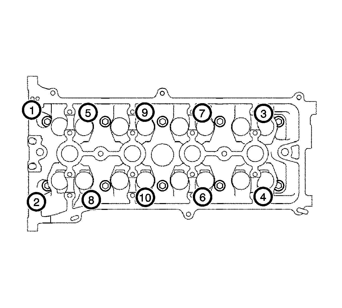
Note: Head warpage or cracking could result from removing the bolts in the wrong order.
- In several steps, uniformly loosen and remove the 10 cylinder head bolts and 10 plate washers with a 10 mm bi-hexagon wrench in the sequence shown in the illustration.
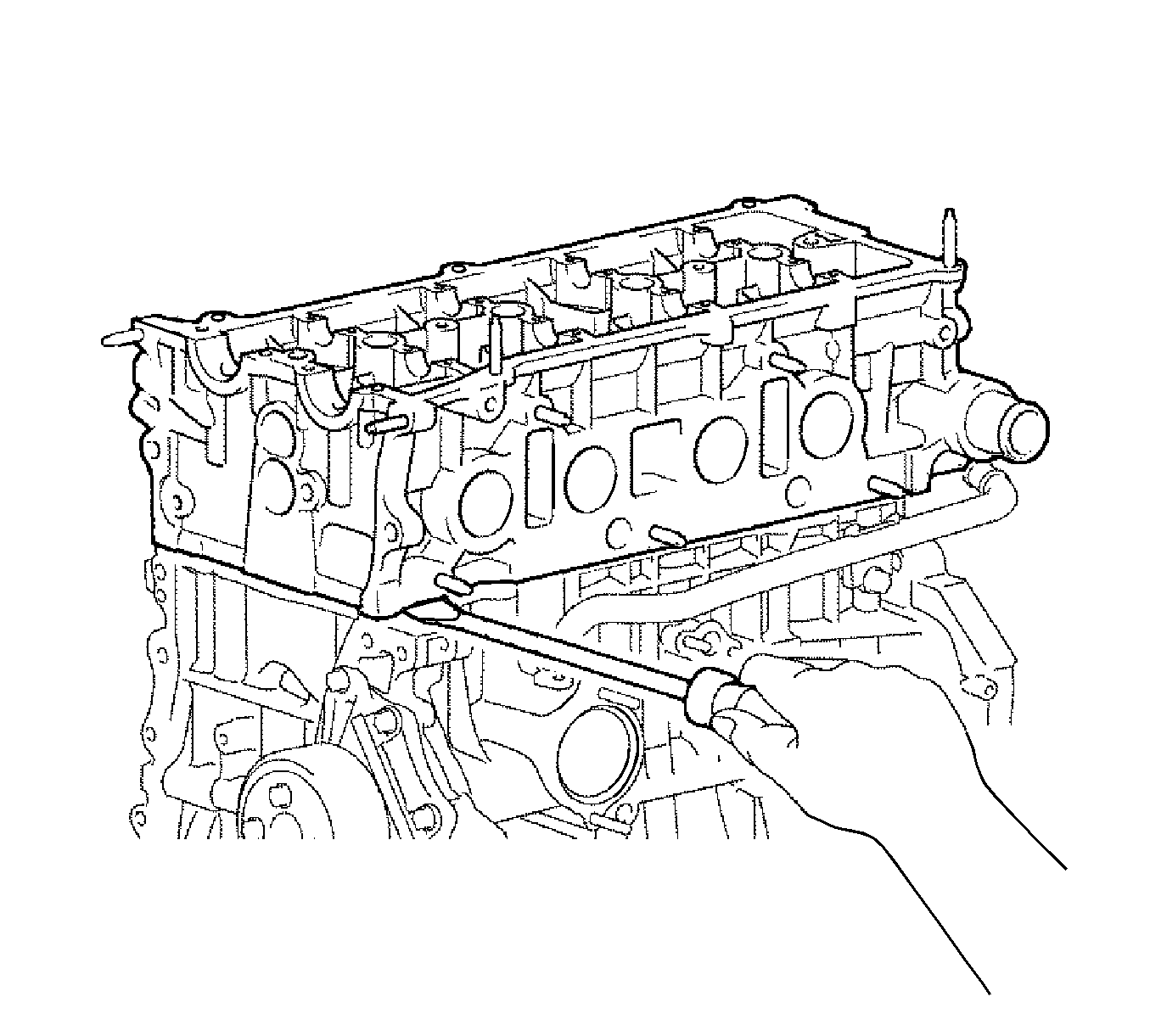
Note: Be careful not to damage the contact surfaces between the cylinder head and cylinder block.
- Using a screwdriver with its tip wrapped with tape, pry between the cylinder head and cylinder block, and remove the cylinder head.
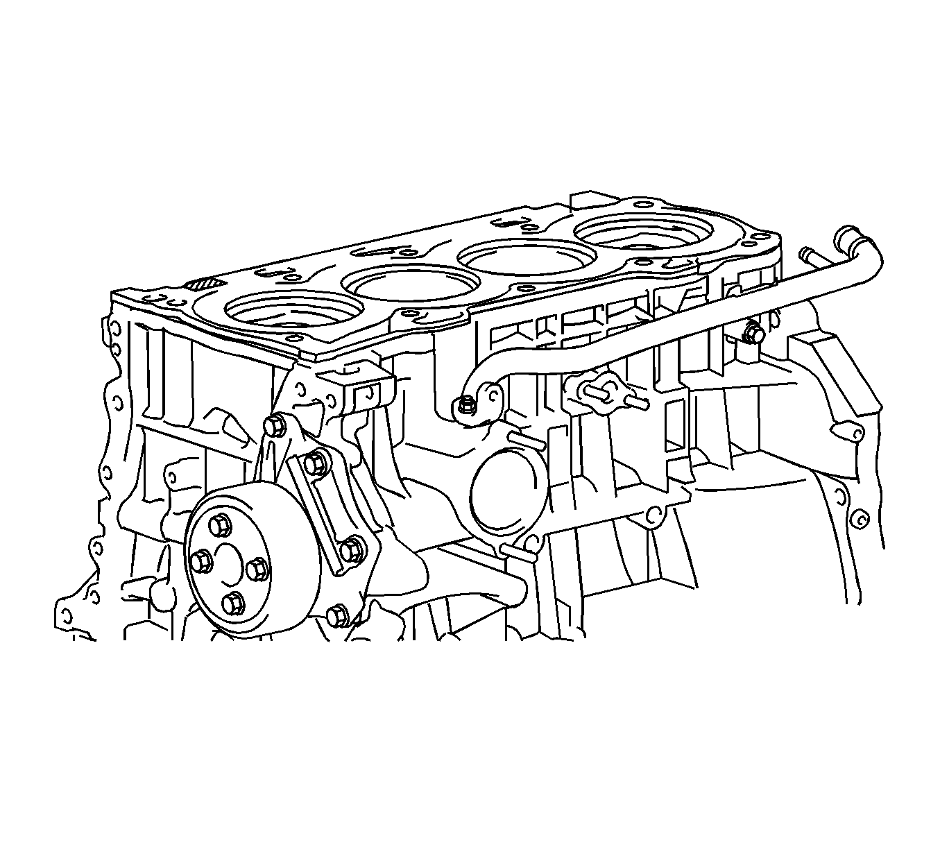
- Remove cylinder head gasket.
Installation Procedure
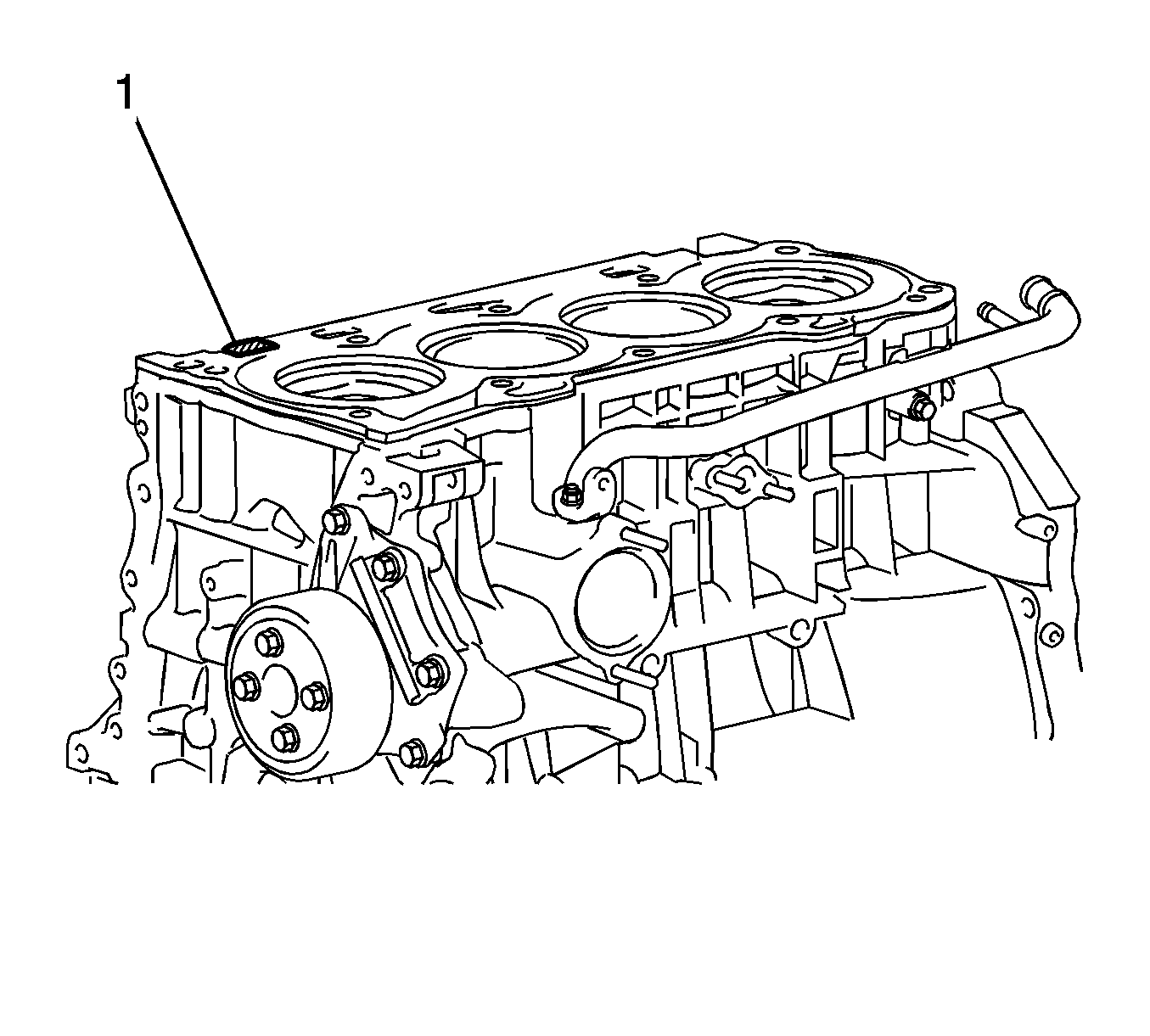
Note: Remove any oil from the contact surface. Be careful of the installation direction.
- Place a new cylinder head gasket on the cylinder block surface with the Lot No. stamp (1) facing upward.
- Install the cylinder head sub-assembly.
Note: Place the cylinder head gently in order to avoid damaging the cylinder head gasket.
- Place the cylinder head on the cylinder head gasket.
Caution: Refer to Fastener Caution in the Preface section.
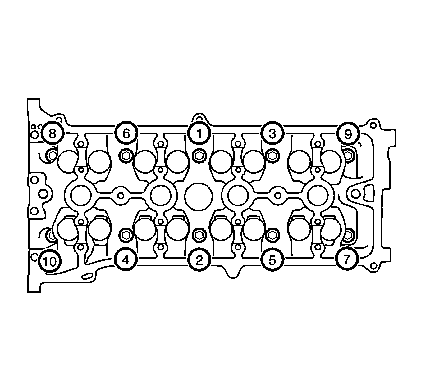
Note: The cylinder head bolts are tightened in 2 successive steps. Apply a light coat of engine oil to the threads and under the heads of the cylinder head set bolts. Using several steps, uniformly install and tighten the 10 cylinder
head set bolts and plate washers with a 10 mm bi-hexagon wrench in the order shown in the illustration.
- Install the cylinder head bolts and tighten to
70 N·m (52 lb ft).
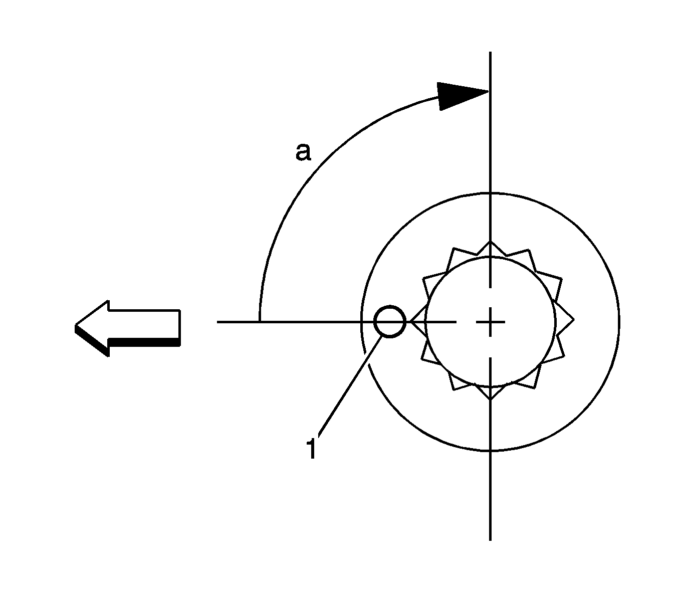
- Mark the front of the cylinder head bolts with paint (1).
- Further tighten the cylinder head bolts by 90 degrees as shown in the illustration.
- Check that the paint mark is now at a 90 degrees angle (a) to the front.
- Install the intake camshaft. Refer to
Intake Camshaft and Valve Lifter Replacement.
- Install the exhaust camshaft. Refer to
Exhaust Camshaft and Valve Lifter Replacement.
- Connect the inlet heater water hose.
- Connect the outlet heater water hose.
- Connect the radiator hose.
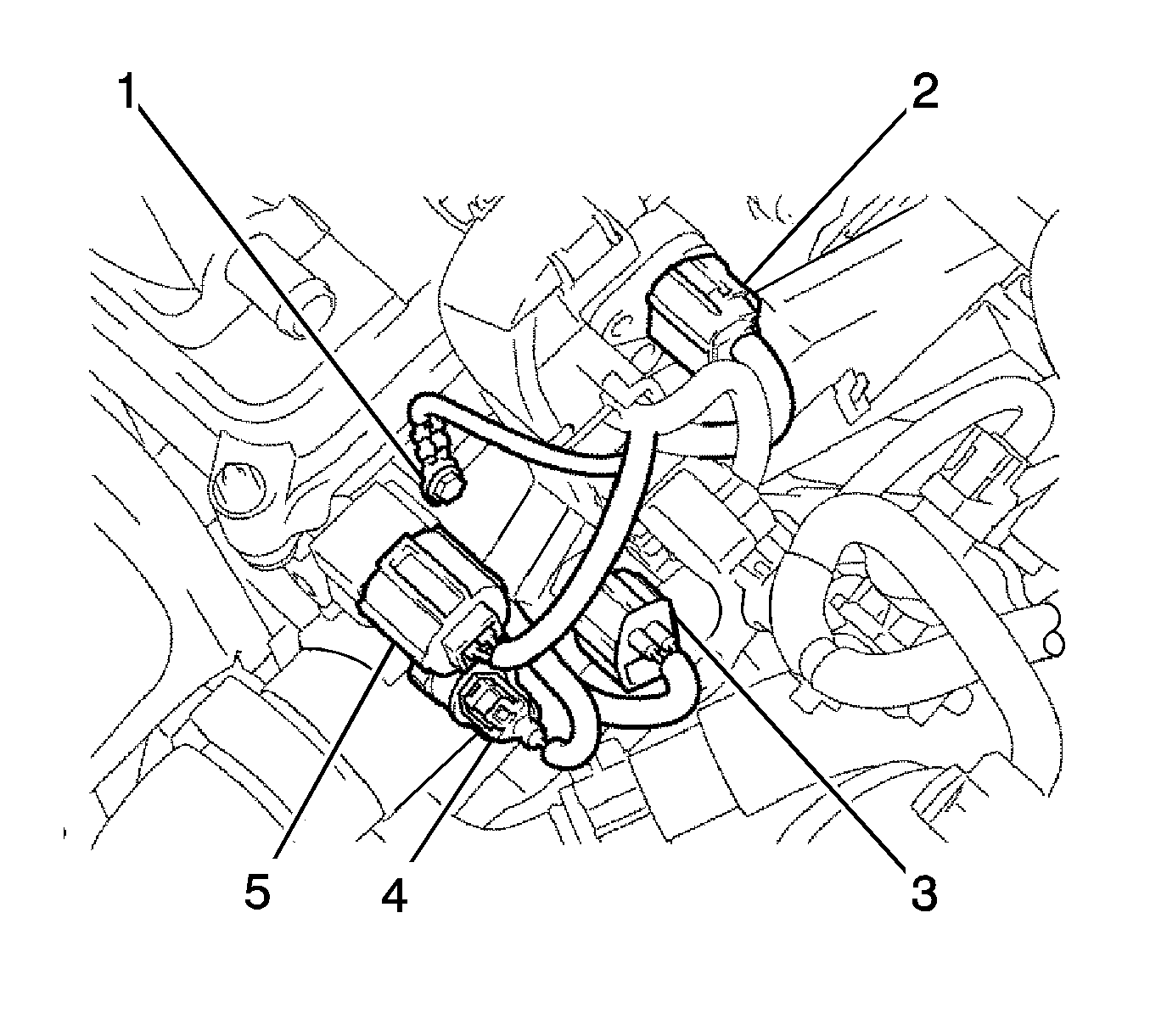
- Connect engine wire.
| • | Connect the ground cable with the bolt (1) and tighten to
8.4 N·m (74 lb in). |
| • | Connect the camshaft position sensor connector. |
| • | Connect the engine coolant temperature sensor connector. |
| • | Connect the engine oil pressure switch connector. |
| • | Connect the radio setting condenser connector. |
| • | Connect the heater water inlet hose. |
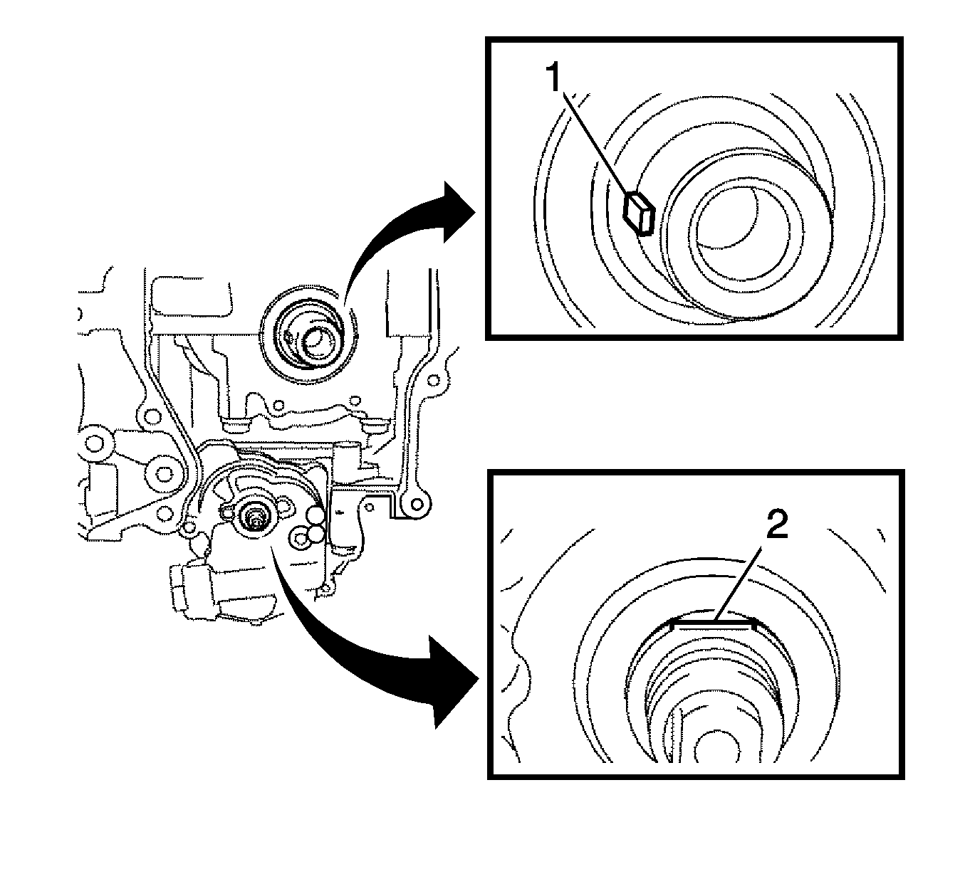
- Set the crankshaft key (1) in the left horizontal position.
- Turn the cutout of the oil pump drive shaft (2) so that it faces upward.
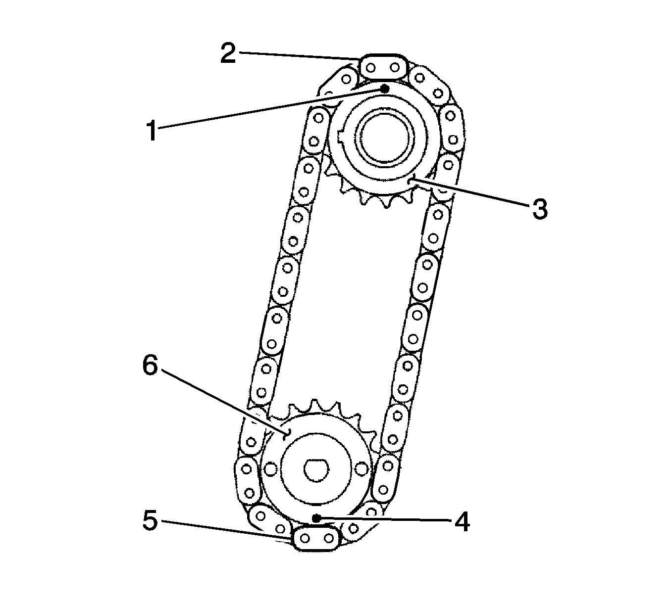
- Align the yellow mark links (2, 5) with the timing marks of each gear (1, 4) as shown in the illustration.
- Install the sprockets onto the crankshaft and oil pump shaft with the chain wrapped on the gears.
- Temporarily tighten the oil pump drive shaft sprocket with the nut.
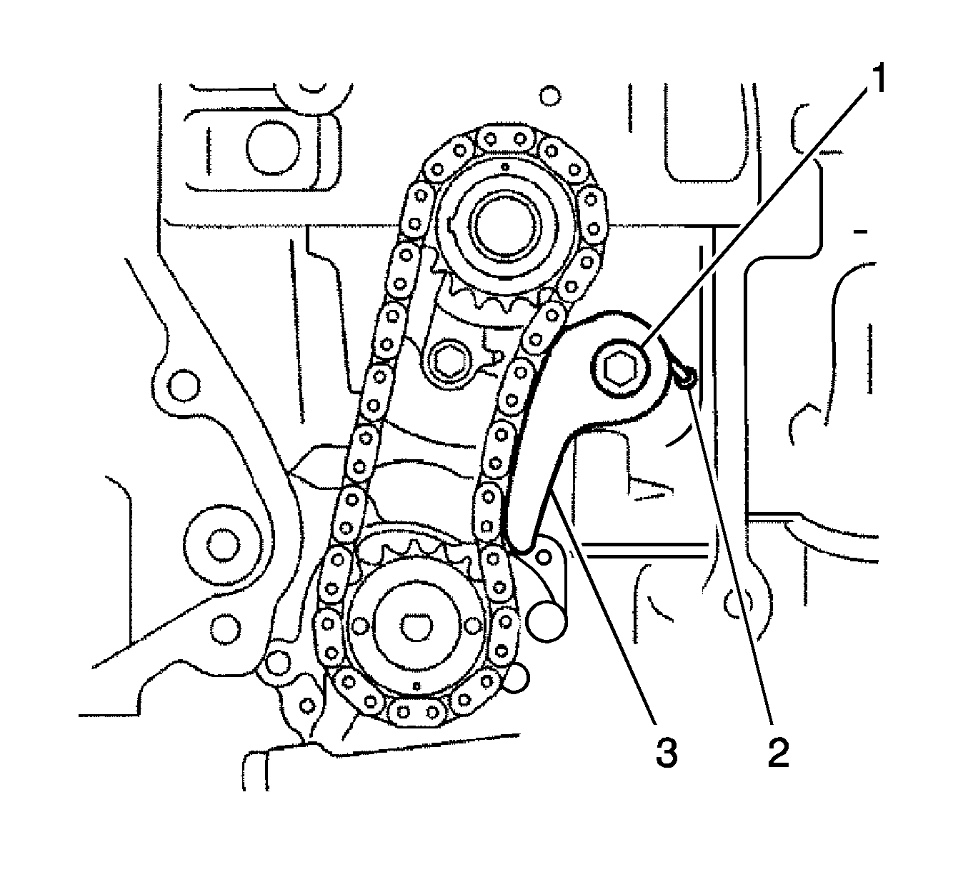
- Insert the damper spring (2) into the adjusting hole, and then install the chain tensioner plate (3) with the bolt (1) and tighten
to
12 N·m (9 lb ft).

- Align the adjusting hole on the oil pump drive shaft sprocket with the groove on the oil pump.
- Insert a 4 mm diameter bar (1) into the adjusting hole on the oil pump drive shaft gear to lock the gear in position, and then tighten the nut to
30 N·m (22 lb ft).

- Install the crankshaft timing gear (1) to the crankshaft.
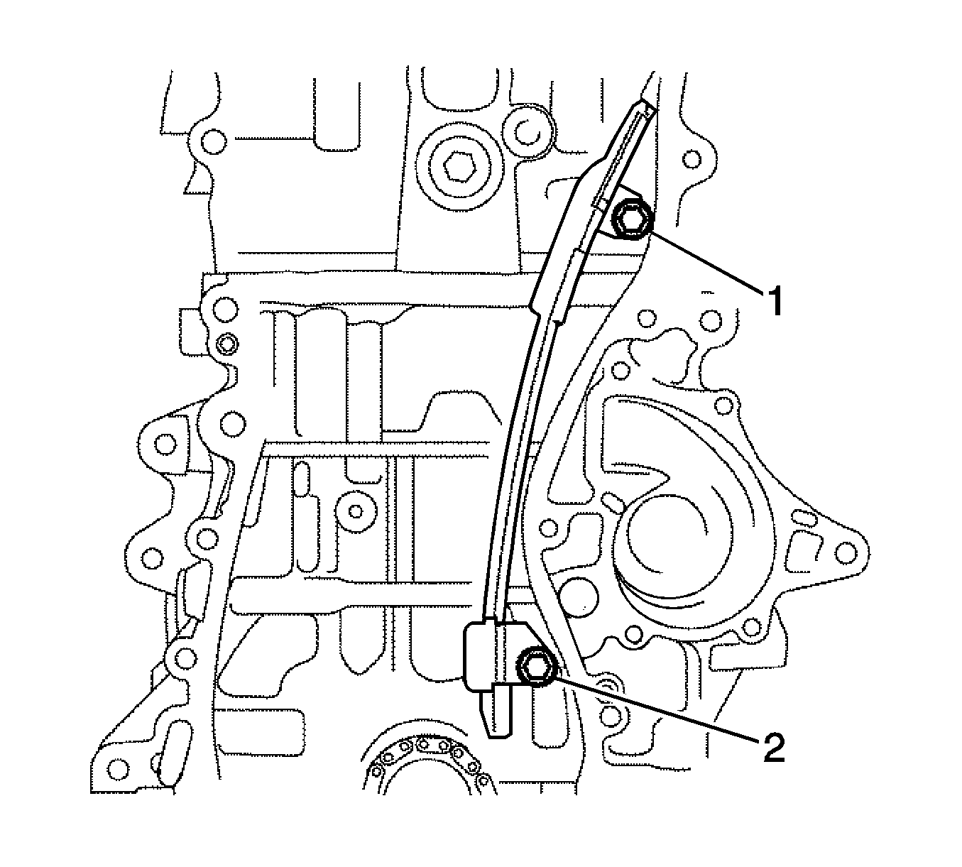
- Install the chain vibration damper with the 2 bolts (1, 2) and tighten to
9.0 N·m (80 lb in).
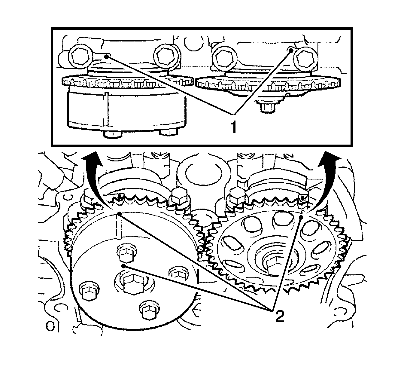
- Set the No. 1 cylinder to TDC/compression.
- Turn the camshafts with a wrench (using the hexagonal lobe) to align the timing marks on the camshaft timing gear (2) with the timing marks located on the bearing caps (1) as shown in the illustration.
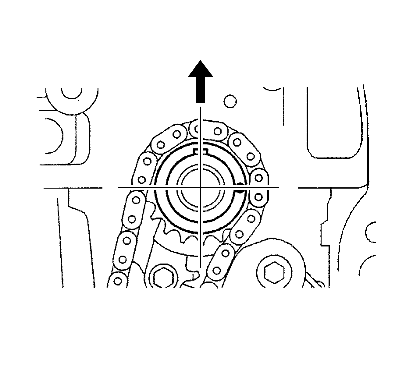
- Using the crankshaft pulley bolt, turn the crankshaft to position the key on the crankshaft upward.
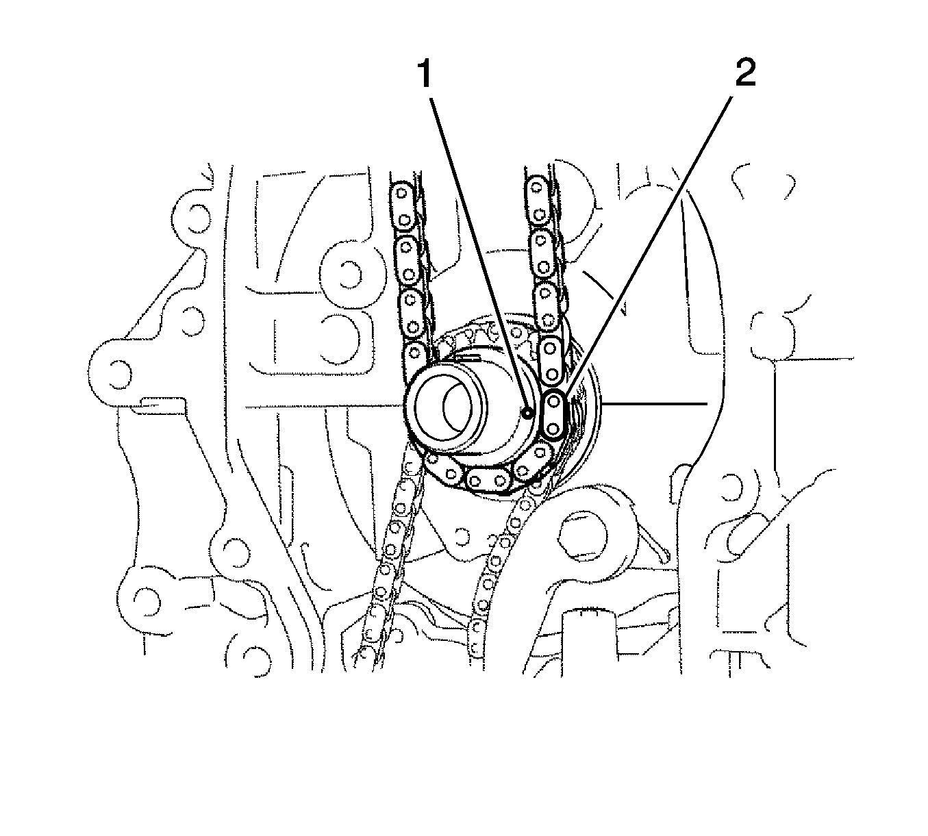
- Install the chain onto the crankshaft timing sprocket with the gold or orange mark link (2) aligned with the timing mark (1) on the crankshaft.
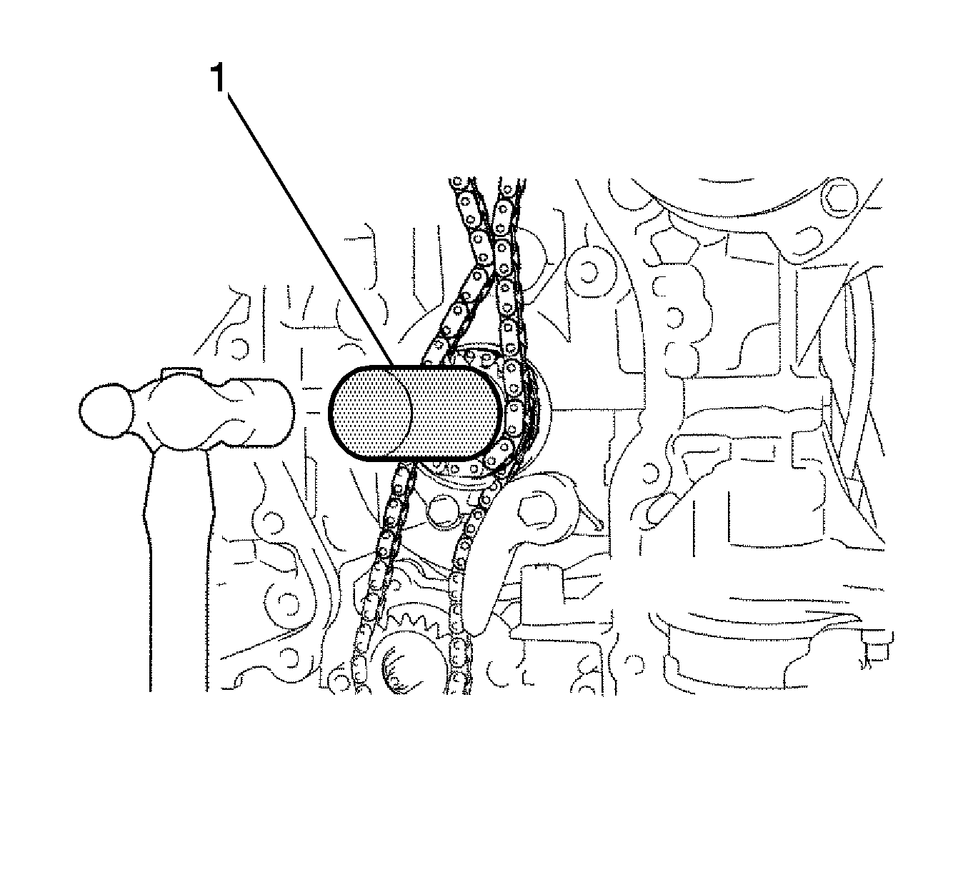
- If necessary, tap in the crankshaft timing sprocket with a suitable tool (1).
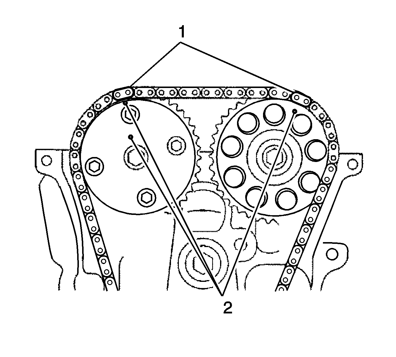
- Align the gold or yellow links (1) with the timing marks located on the camshaft timing gear (2) , then install the chain.
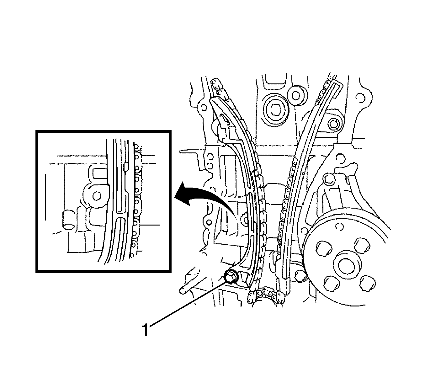
- Install the chain tensioner slipper with the bolt (1) and tighten to
19 N·m (14 lb ft).

- Install the timing chain guide with the bolt (1) and tighten to
9.0 N·m (80 lb in).
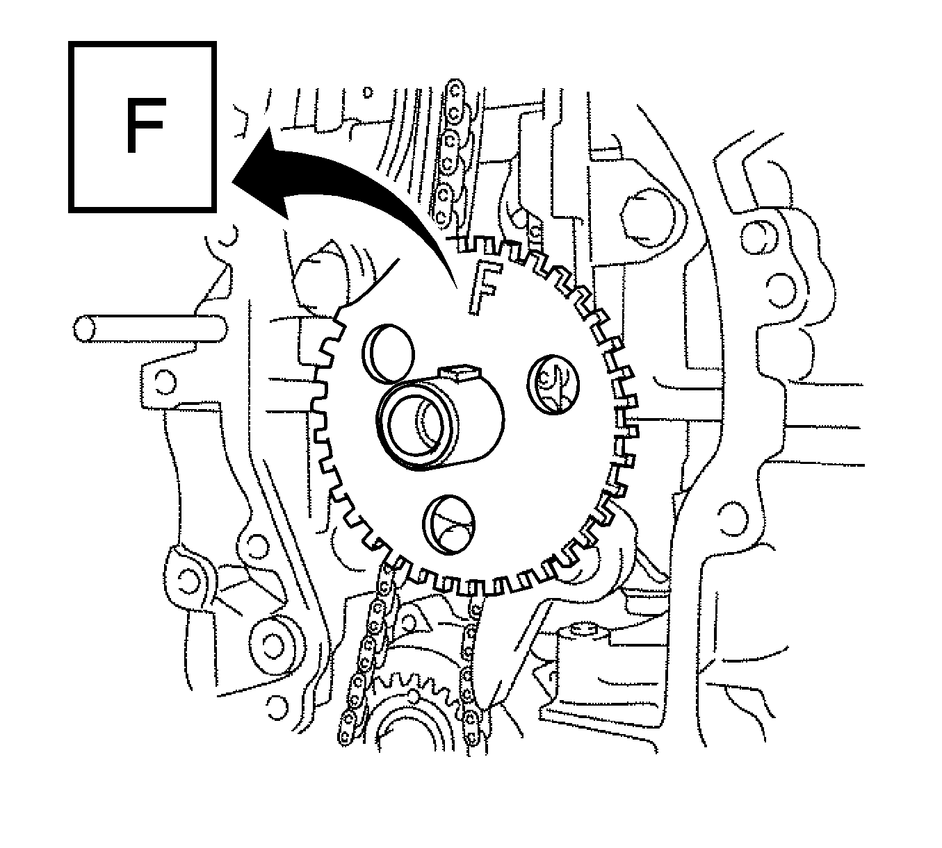
- Install the crankshaft position sensor plate. Install the sensor plate with the "F" mark facing forward.
- Install the timing chain or belt cover sub-assembly. Refer to
Timing Chain Housing Installation.
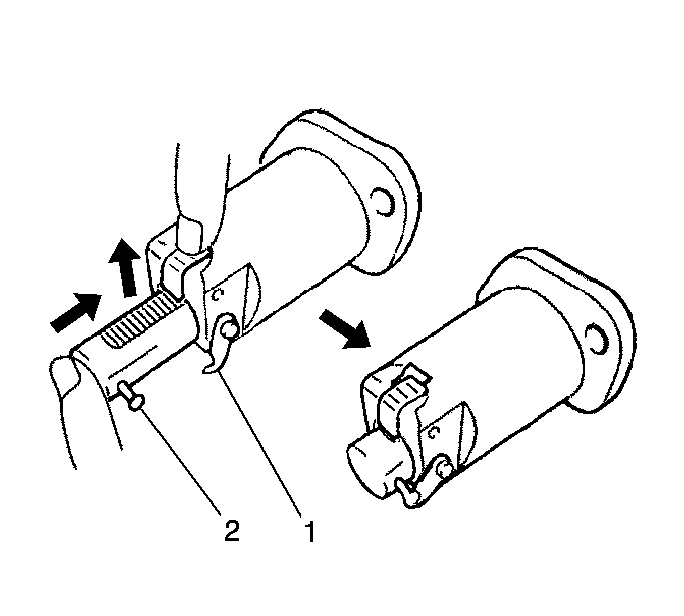
- Release the ratchet pawl, then fully push in the plunger and set the hook (1) to the pin (2) so that the plunger is in the position shown
in the illustration.
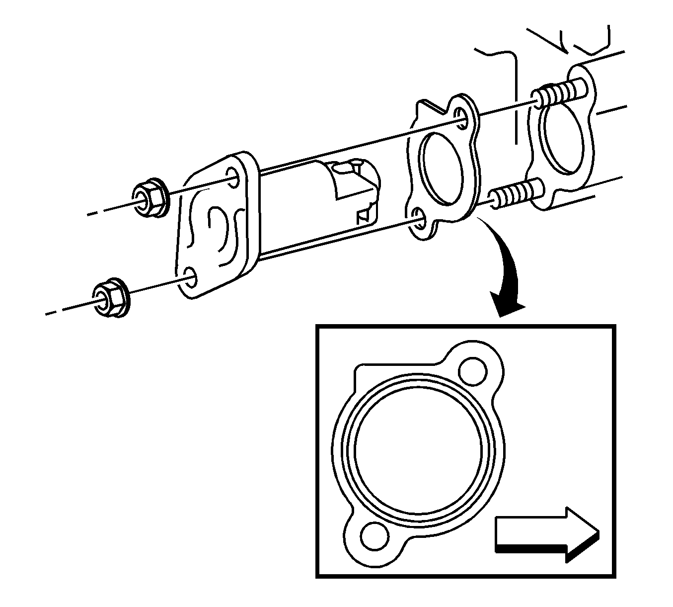
Note: When installing the chain tensioner, set the hook again if the hook releases the plunger.
- Install a new gasket and the chain tensioner with the 2 nuts and tighten to
9.0 N·m (80 lb in).
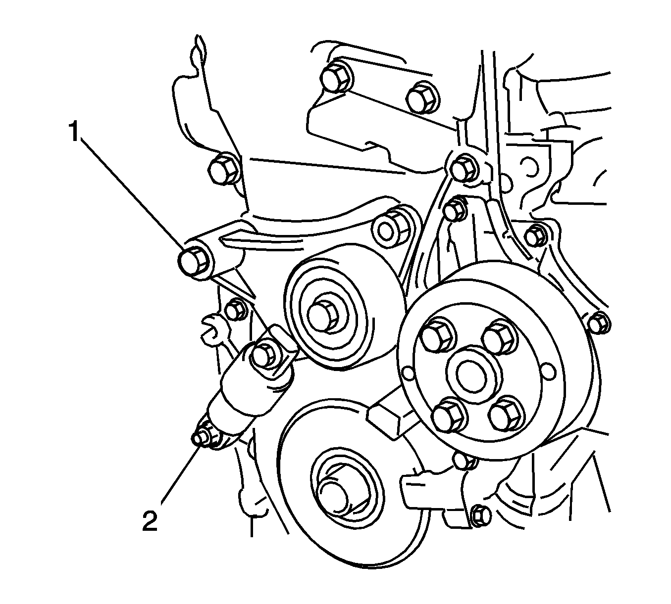
Note: Do not lift the engine more than necessary.
- Except the spring type V-ribbed belt tensioner--Install the V-ribbed tensioner assembly with the bolt (1) and nut (2) and tighten to
60 N·m (44 lb ft).
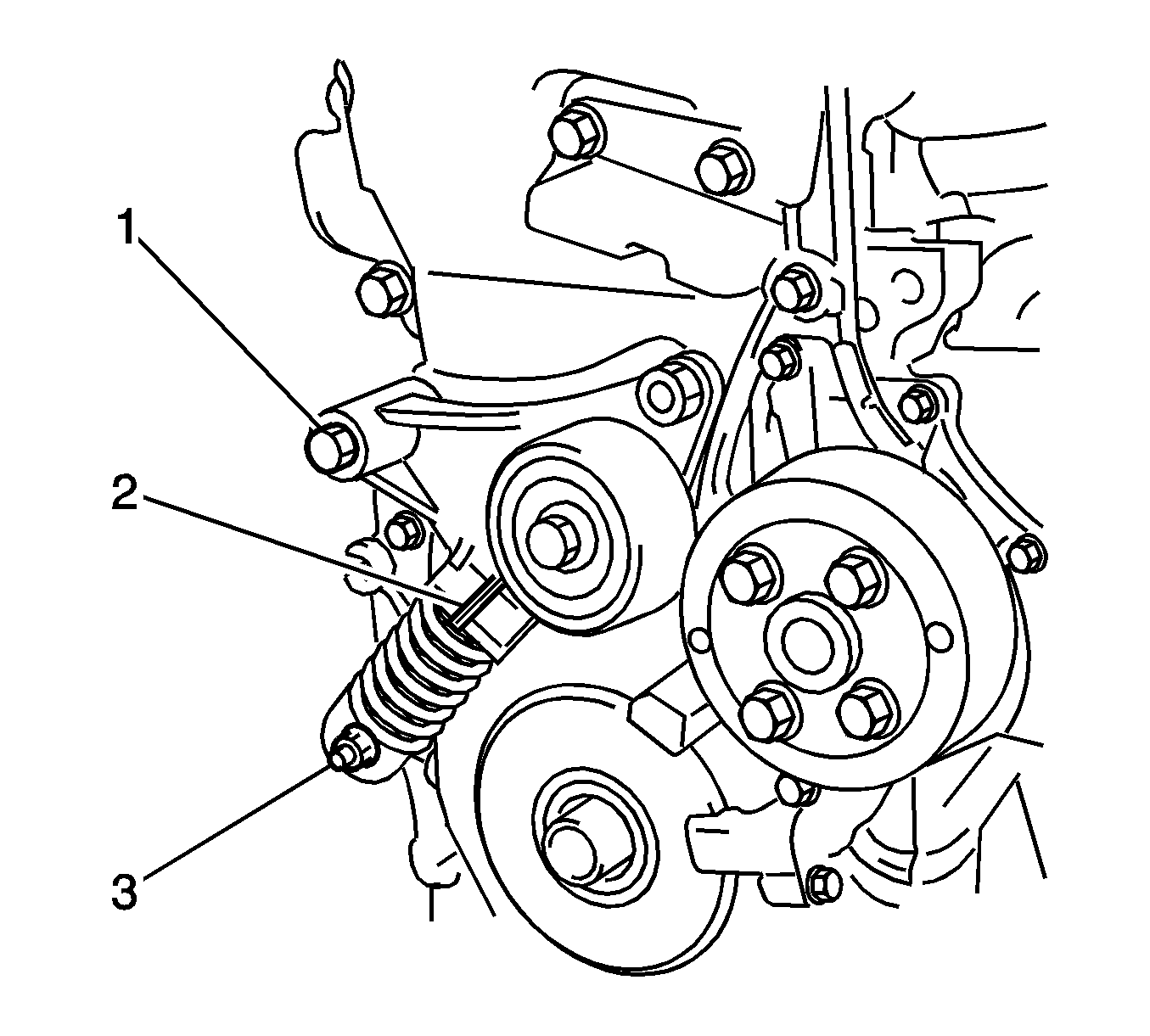
Note: When replacing the V-ribbed belt tensioner with a new one, do not pull out the pin. Do not lift the engine more than necessary.
- Spring type V-ribbed belt tensioner--Install the V-ribbed belt tensioner to the engine by first tightening the bolt (1) and then tightening the nut (1) to
60 N·m (44 lb ft).

- Install the engine transverse engine mounting bracket with the 3 bolts (1, 2, 3) and tighten to
55 N·m (41 lb ft).
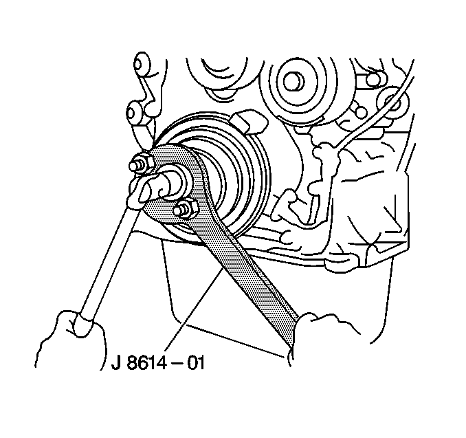
- Install the crankshaft pulley.
- Using the
J-8614-A holder and remover
, fix the pulley in place and tighten the bolt to
180 N·m (133 lb ft).
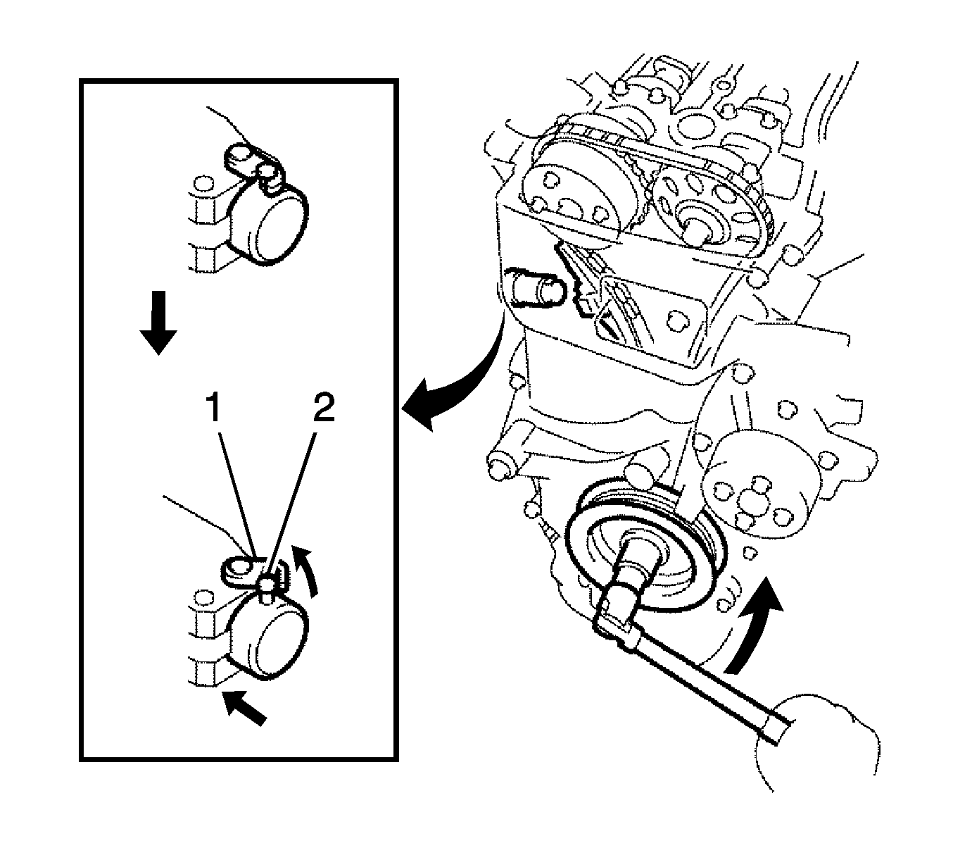
- Turn the crankshaft counterclockwise, then disconnect the plunger knock pin (2) from the hook (1).
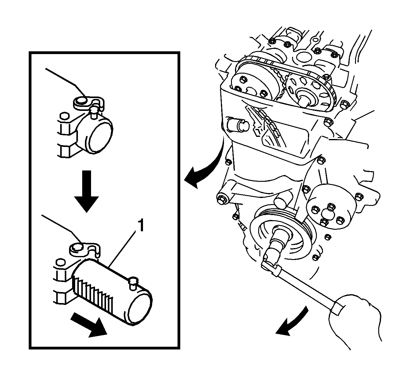
- Turn the crankshaft clockwise, then check that the plunger (1) is extended.
- Remove any old packing material and be careful not to drop any oil on the contact surfaces of the cylinder block and oil pan.
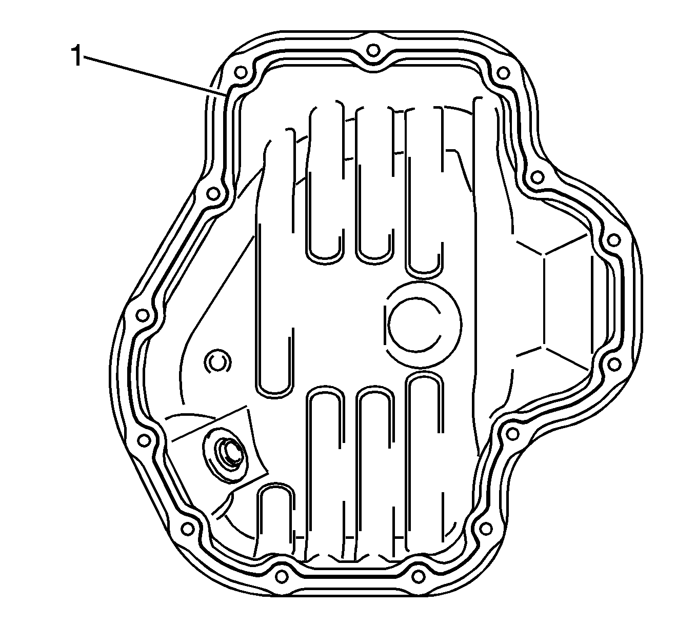
Note: Remove any oil from the contact surfaces. Install the oil pan within 3 minutes of applying seal packing. Do not add engine oil for at least 2 hours after installing the oil pan.
- Apply a continuous bead of sealant, diameter 4.0-4.5 mm (0.158-0.177 in), as shown in the illustration, Three Bond 1217B or equivalent GM part number 12378521 (Canadian part number 88901148).
- Install the oil pan (1) onto the cylinder block.
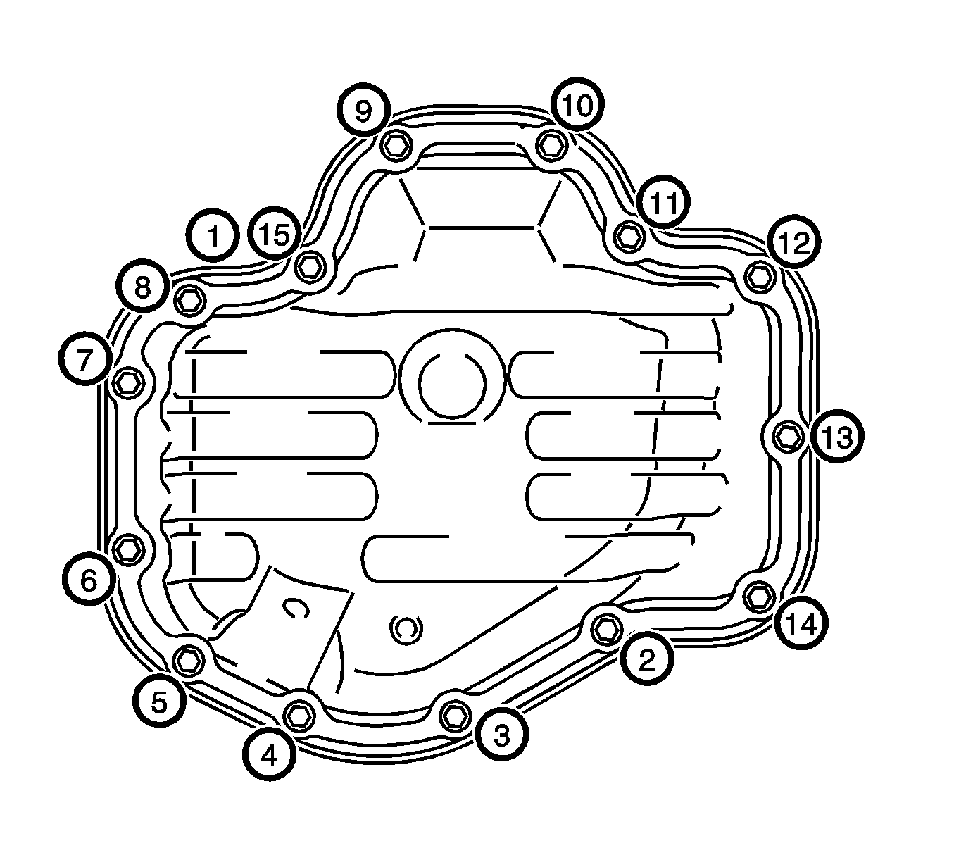
- Uniformly tighten the 12 bolts and 2 nuts in the sequence shown in the illustration to
9.0 N·m (80 lb ft).
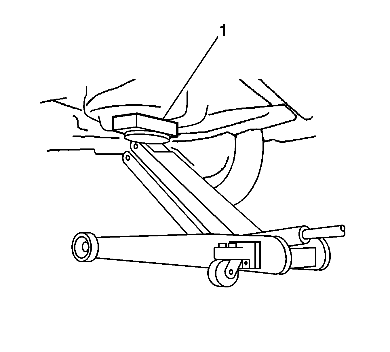
- Place a wooden block (1) between a floor jack and the engine, then support the engine using the floor jack.
- Remove the engine support fixture.
- Install the crankshaft position sensor.

- Install the idler pulley sub-assembly with the 2 bolts (1, 2) and tighten to
50 N·m (37 lb ft).
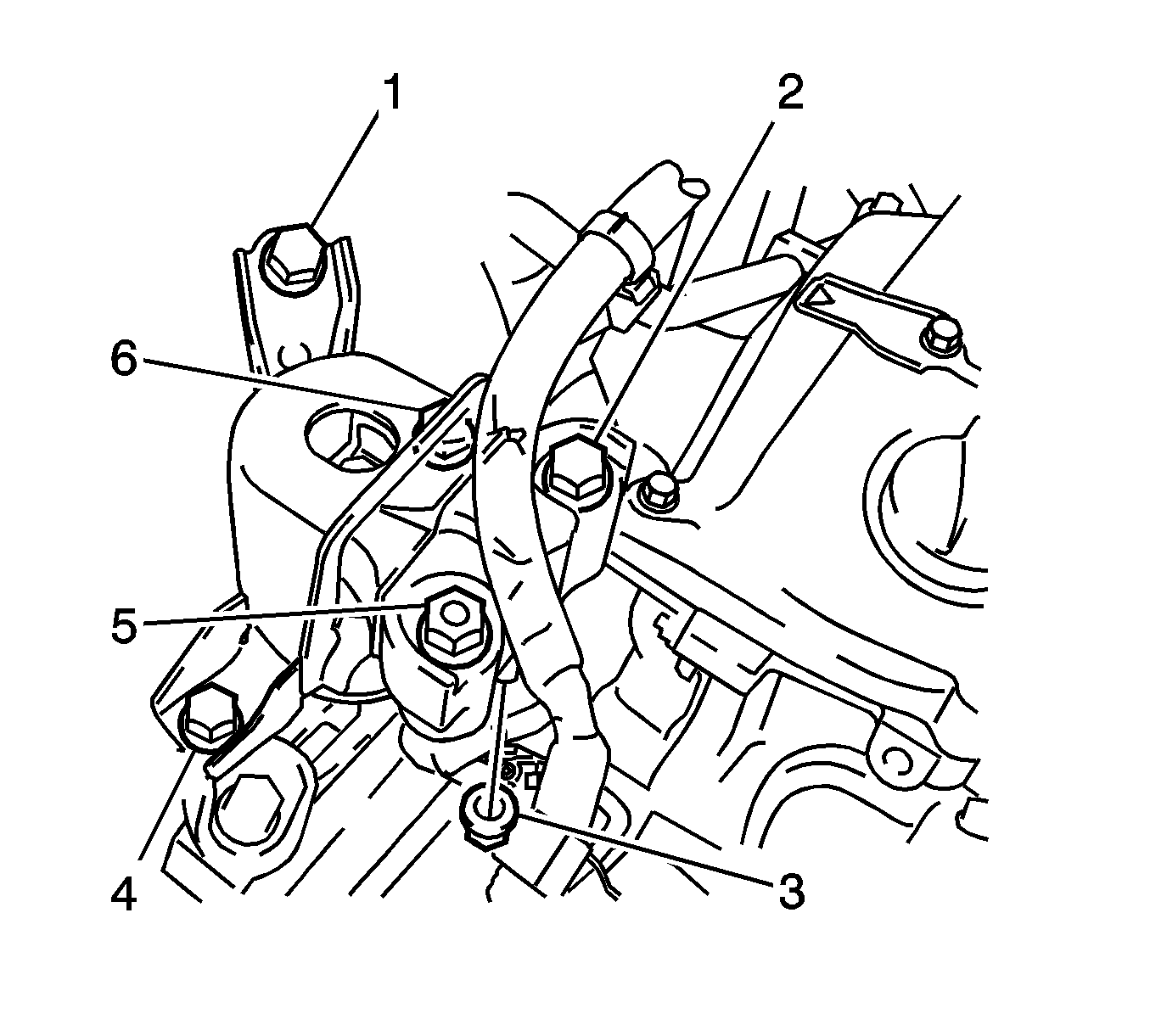
- Install the right engine mounting insulator sub-assembly with the 4 bolts (1, 2, 4, 6) and 2 nuts (3, 5) and tighten.
| • | Bolts 1, 4 and 6 to
52 N·m (38 lb ft) |
| • | Bolt 2 to
95 N·m (70 lb ft) |
| • | Nut 5 to
95 N·m (70 lb ft) |
| • | Nut 3 to
52 N·m (38 lb ft) |
- Install the exhaust manifold converter assembly. Refer to
Exhaust Manifold Replacement.
- Install the intake manifold. Refer to
Intake Manifold Replacement.
- Install the camshaft timing oil control valve assembly.
- Install the fuel delivery pipe assembly.
- Connect the fuel main tube.
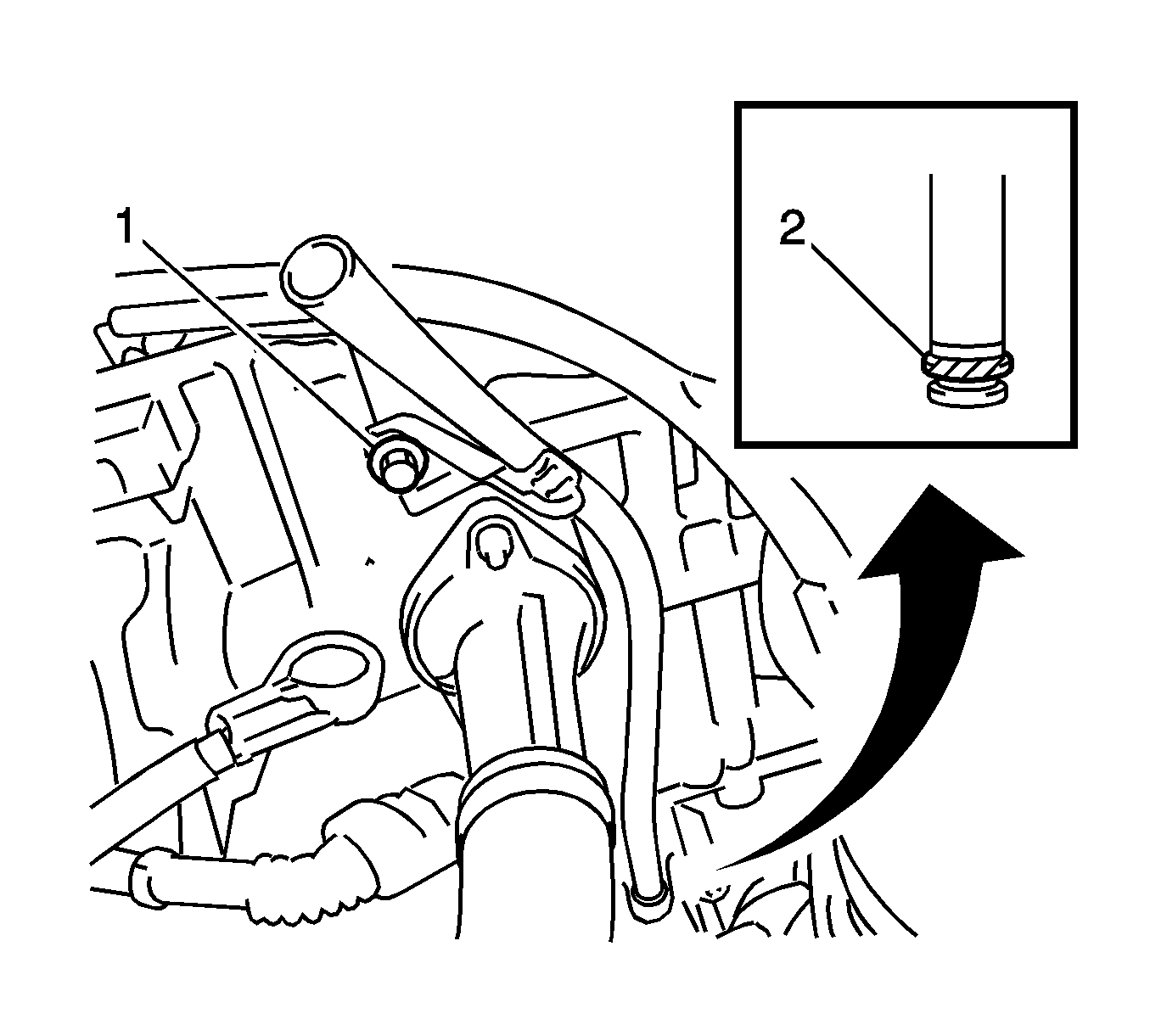
- Apply a light coat of engine oil to a new O-ring (2) and install it onto the engine oil level dipstick guide.
- Install the engine oil level dipstick guide with the bolt (1) and tighten to
9.0 N·m (80 lb ft).
- Install the engine oil level dipstick.
- Install the cylinder head cover. Refer to
Camshaft Cover Replacement.
- Install the spark plug. Refer to
Spark Plug Replacement.
- Install the ignition coil assembly. Refer to
Ignition Coil Replacement.
- Install the throttle body assembly.
- Install the air cleaner cap with hose.
- Install the radiator reserve tank assembly.
- Install the generator assembly. Refer to
Generator Replacement.
- Install the V-ribbed belt. Refer to
Drive Belt Replacement
- Install the front exhaust pipe assembly. Refer to
Front Pipe Replacement.
- Install the catalytic converter assembly. Refer to
Catalytic Converter Replacement.
- Connect the cable to negative battery terminal.
- Add engine oil. Refer to
Engine Oil and Oil Filter Replacement.
- Add engine coolant. Refer to
Cooling System Draining and Filling.
- Inspect for fuel leak.
- Inspect for coolant leak.
- Inspect for oil leak.
- Inspect for exhaust gas leak.
- Inspect the ignition timing.
- Inspect the engine idling speed.
- Install the suspension tower damper assembly, with front strut bar.
- Install the outer cowl top panel.
- Install the windshield wiper motor and link assembly. Refer to
Windshield Wiper Motor Replacement.
- Install the engine cover. Refer to
Engine Cover Replacement.
- Install the left engine under cover.
- Install the right engine under cover.
- Install the right front wheel.


