Removal Procedure
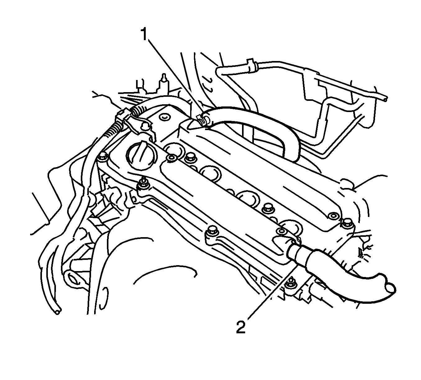
- Remove the right engine under cover.
- Remove the engine cover. Refer to
Engine Cover Replacement.
- Remove the ignition coil assembly. Refer to
Ignition Coil Replacement.
- Remove the spark plug. Refer to
Spark Plug Replacement.
- Remove the 2 ventilation hoses (1, 2) from the cylinder head cover sub-assembly.
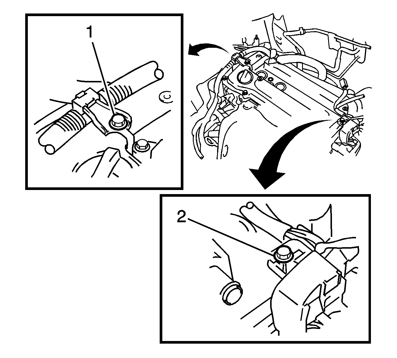
- Remove the 2 bolts (1, 2) and separate the 2 wire harness brackets.
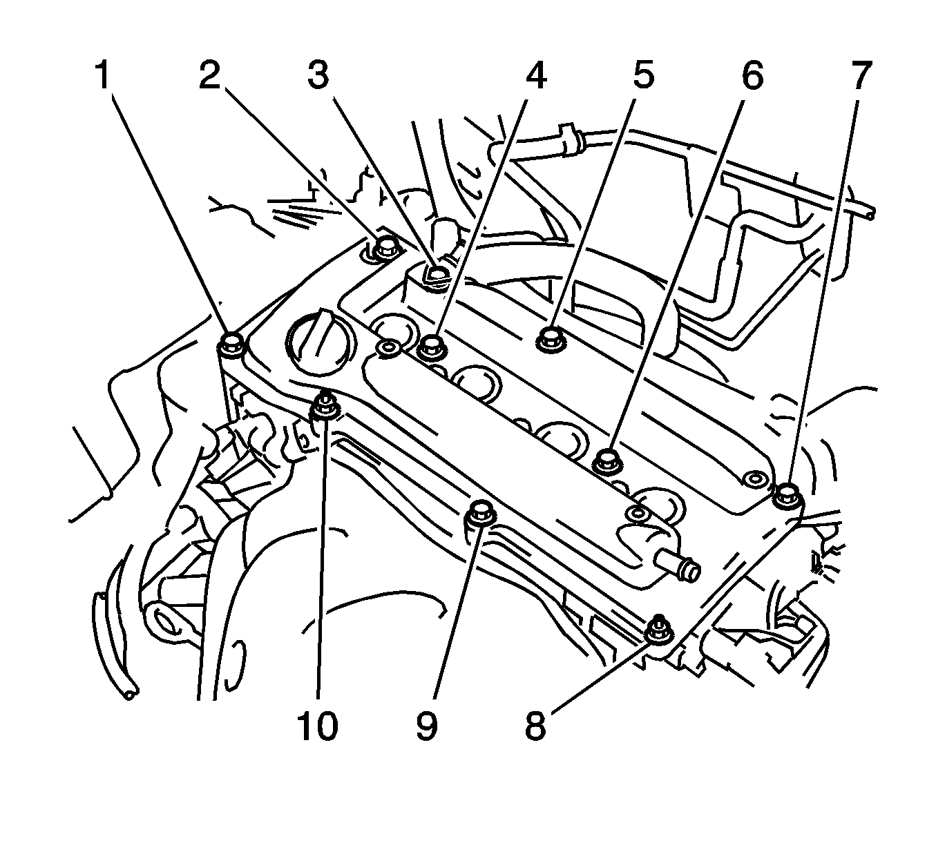
- Remove the 8 bolts (1-7, 9) and 2 nuts (8, 10), then remove the cylinder head cover sub-assembly and gasket.
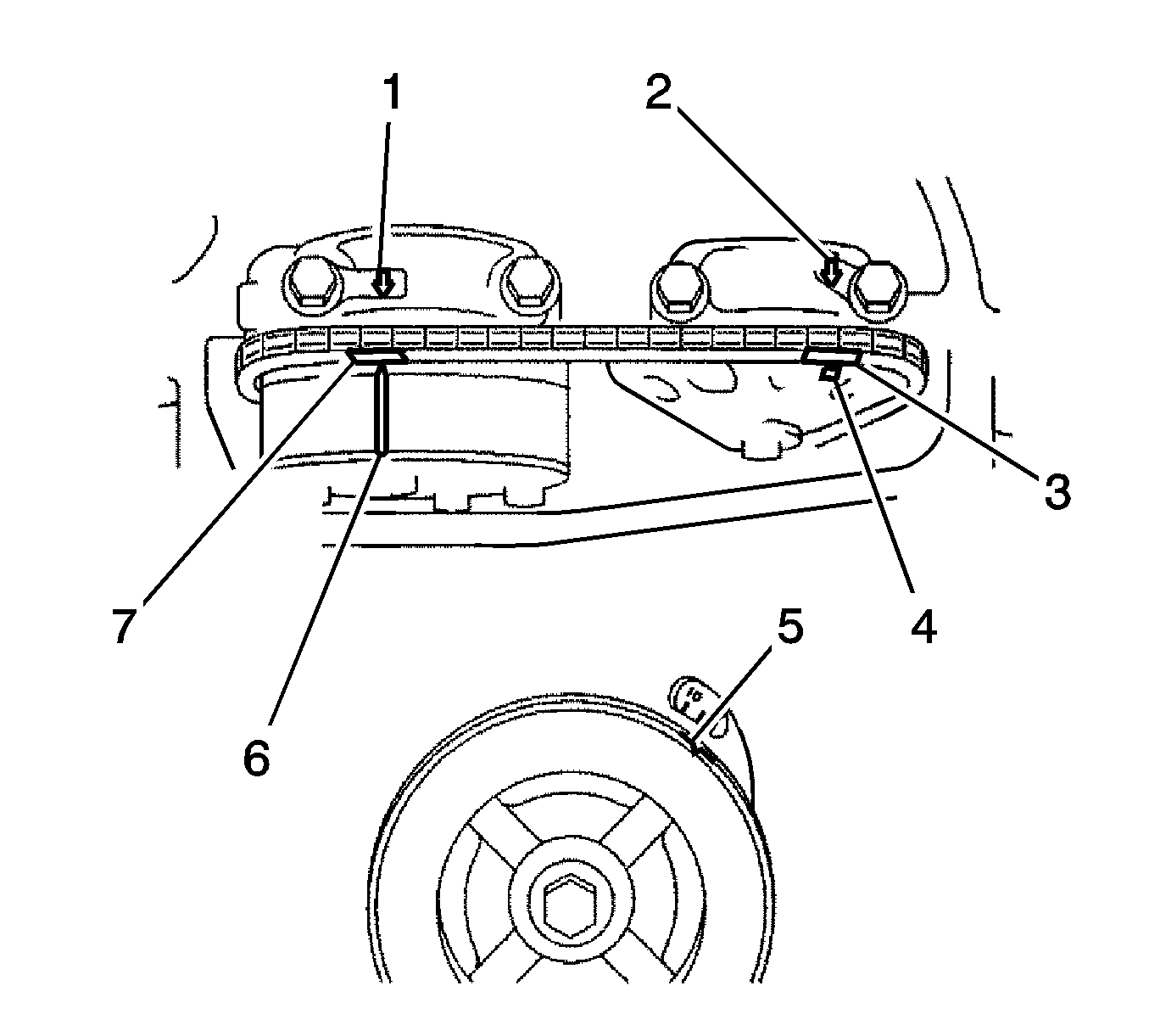
- Set No. 1 cylinder to TDC/compression by turning the crankshaft pulley until the groove (5) and the timing mark "0" on the timing chain cover
are aligned.
- Check that each timing mark on the camshaft timing gear (4, 6) and sprocket is aligned with each timing mark located on the bearing caps (1, 2) , as shown in the illustration.
- If not, turn the crankshaft pulley by 1 revolution (360°) to align the timing marks as illustrated.
- Place paint marks on the chain (3, 7) in alignment with the timing marks on the camshaft timing gear and camshaft timing sprocket.
- Remove the chain tensioner assembly.
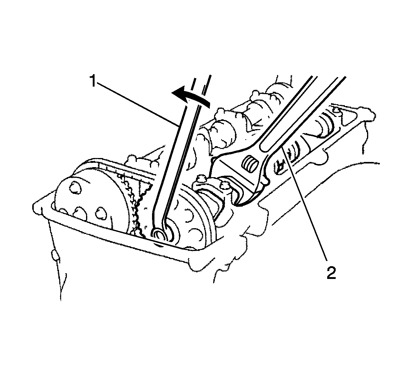
- Loosen the camshaft timing gear or sprocket. While holding the exhaust camshaft with a wrench (2), loosen the No. 2 camshaft timing set bolt.
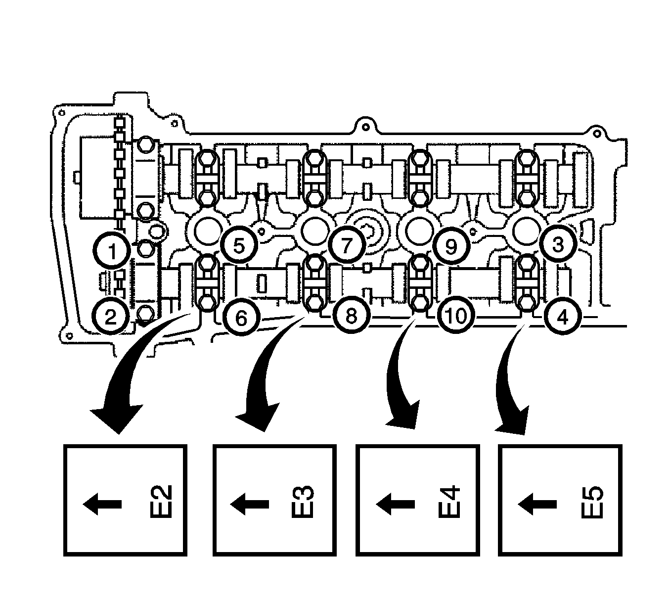
- Remove the exhaust camshaft using several steps, uniformly loosen and remove the 10 bearing cap bolts in the sequence shown in the illustration.
- Remove the 5 bearing caps.
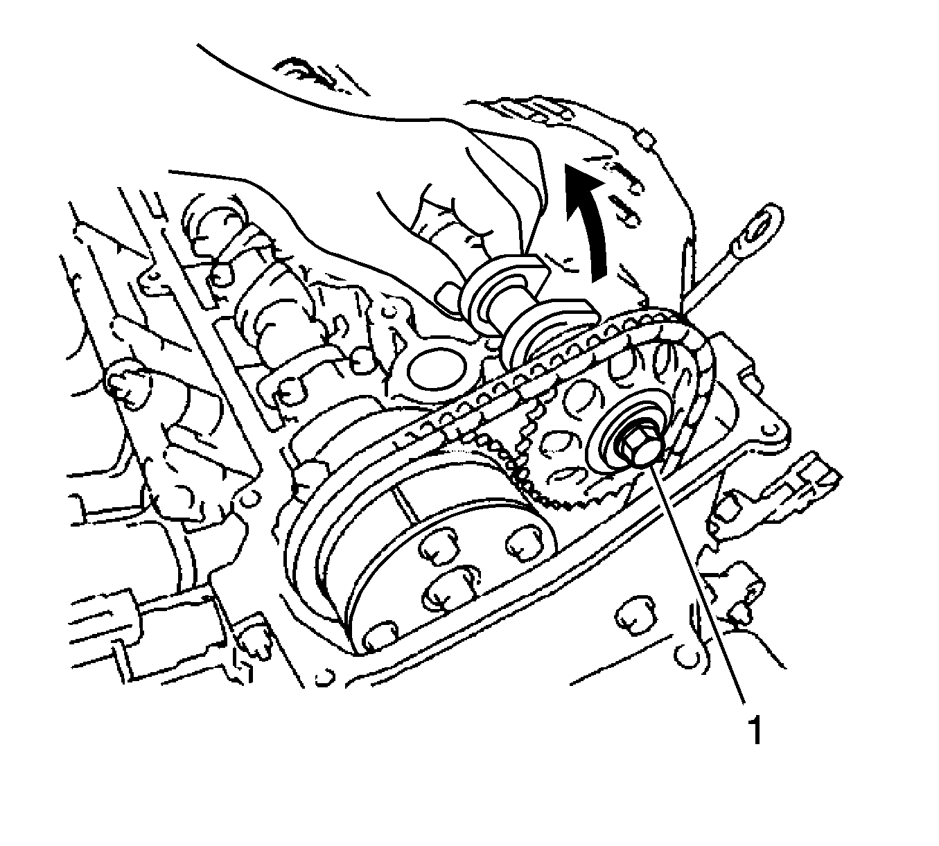
- While holding the exhaust camshaft by hand, remove the camshaft timing sprocket set bolt (1).
- Remove the camshaft timing sprocket from the exhaust camshaft with the timing chain wrapped on the sprocket.
- Remove the camshaft timing sprocket from the timing chain.
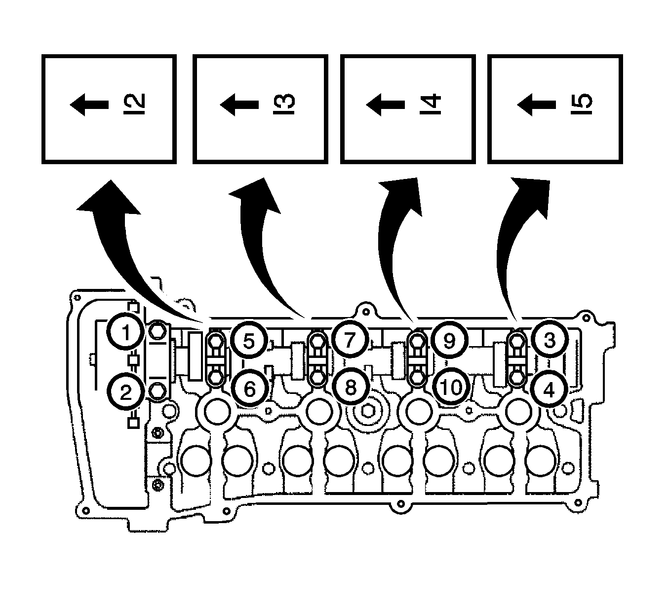
- Remove the intake camshaft using several steps, uniformly loosen and remove the 10 bearing caps bolts in the sequence shown in the illustration.
- Remove the 5 bearing caps.
- Remove the camshaft and camshaft timing gear assembly while holding the timing chain by hand.
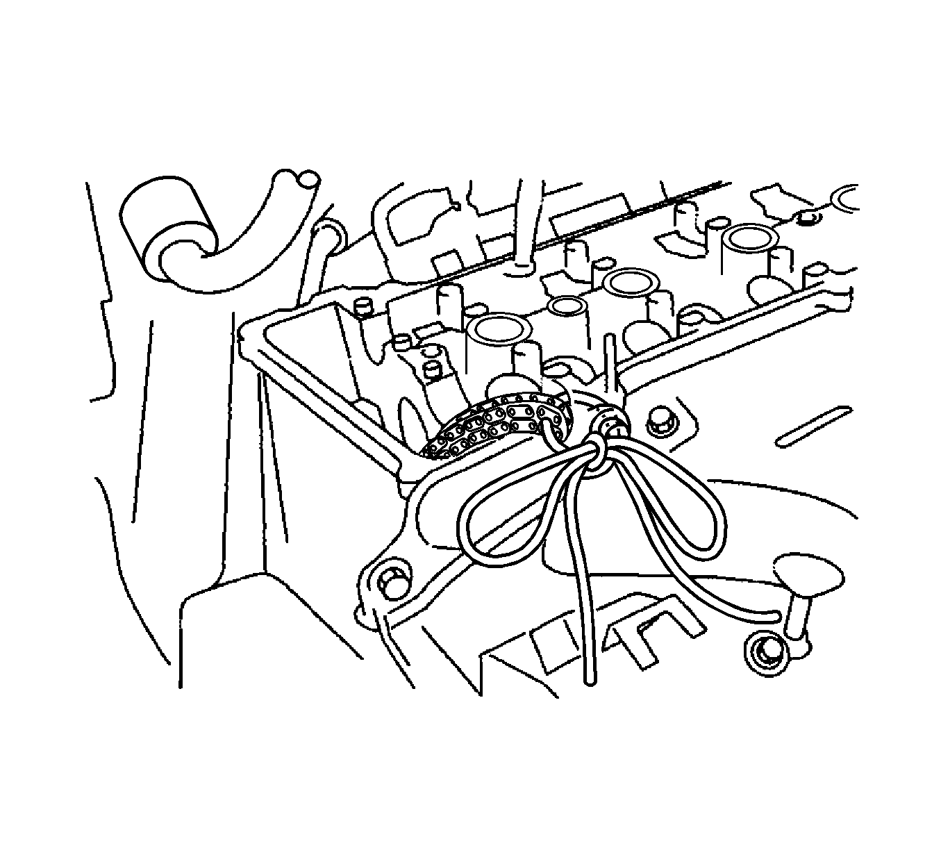
Note: Be careful not to drop anything inside the timing chain cover.
- Support the timing chain with a string to prevent it from slipping off the crankshaft sprocket as shown in the illustration.
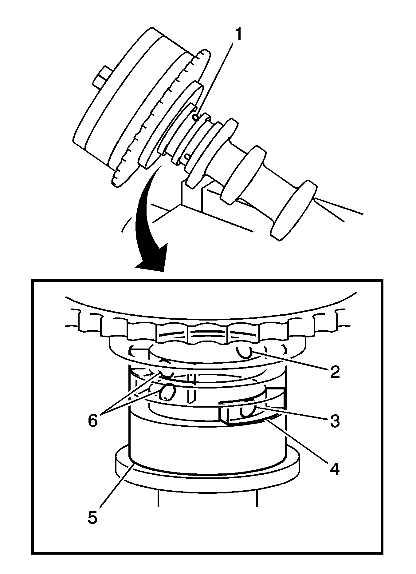
- Remove camshaft timing gear assembly by clamping the camshaft in a vise, and make sure that the camshaft timing gear assembly does not rotate.
- Cover all the oil path with vinyl tape except the advance side path (1) shown in the illustration.
Note: Cover the paths with a piece of cloth to avoid oil splashes.
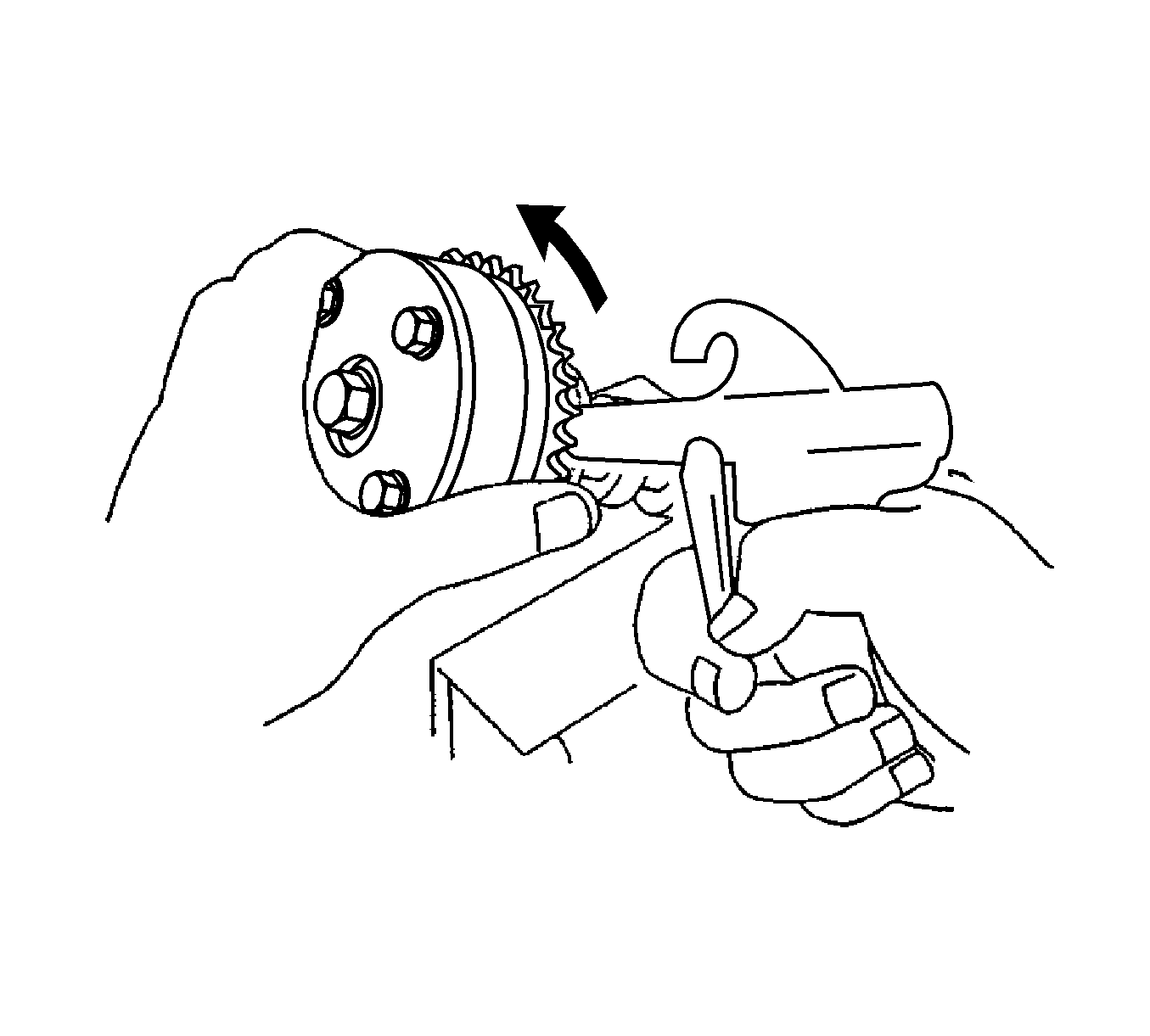
- Apply air pressure of 150 kPa (22 psi) to the oil path, then turn the camshaft timing gear assembly to the advance direction (counterclockwise) by hand.
Note: Be sure not to remove the other 4 bolts. When reusing the camshaft timing gear, release the straight pin lock first, then install the gear.
Note: Depending on the air pressure, the camshaft timing gear assembly may turn to the advance side without applying force by hand. Also, if the pressure is difficult to apply because of air leakage from the port, the lock pin may be
difficult to release.
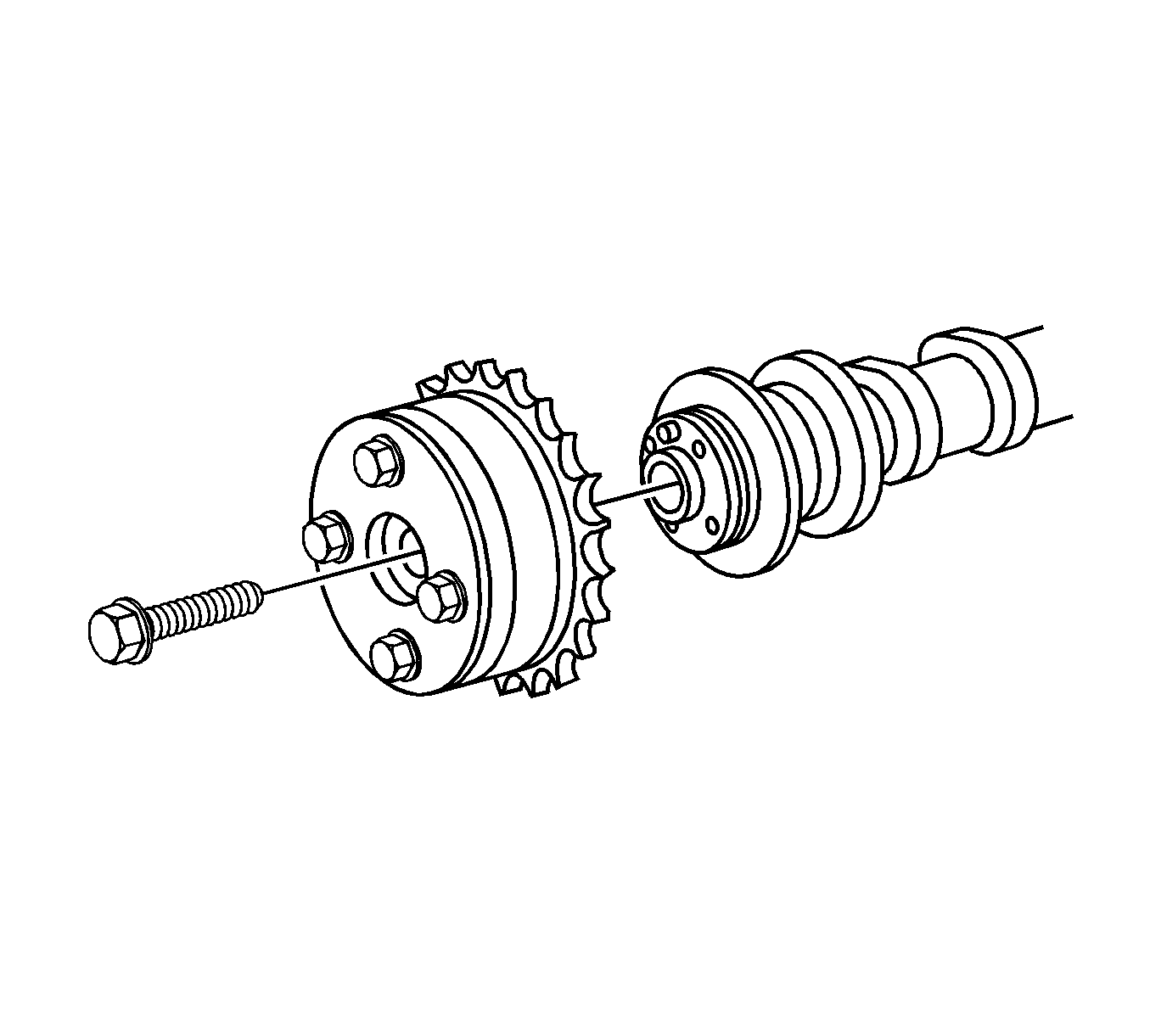
- Remove the flange bolt of the camshaft timing gear.
Inspection Procedure
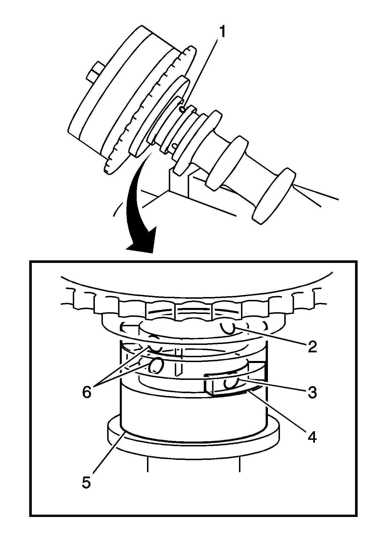
- Inspect camshaft timing gear assembly as follows.
| 1.1. | Install the camshaft timing gear assembly. |
| 1.2. | Clamp the camshaft in a vise, and make sure that the camshaft timing gear assembly does not rotate. |
- Cover all the oil paths with vinyl tape except the advance side path (1) shown in the illustration.

Note: Cover the paths with a piece of cloth to avoid oil splashes.
- Apply air pressure of 150 kPa (22 psi) to the oil path.
Note: Depending on the air pressure, the camshaft timing gear may turn to the advance side without applying force by hand. Also, if enough air pressure cannot be applied because of air leakage from the path, releasing the lock pin may
be difficult.
- Check that the camshaft timing gear revolves in the advance direction (counterclockwise) by hand.
Note: Do not use air pressure to perform the smooth rotation check.
- Check for smooth rotation. Turn the camshaft timing gear within its movable range (21°) 2 or 3 times, but do not turn it to the most retarded position. Make sure that the gear turns smoothly.
- Check the lock in the most retarded position. Confirm that the camshaft timing gear is locked at the most retarded position.
- Remove the camshaft timing gear assembly.
Installation Procedure
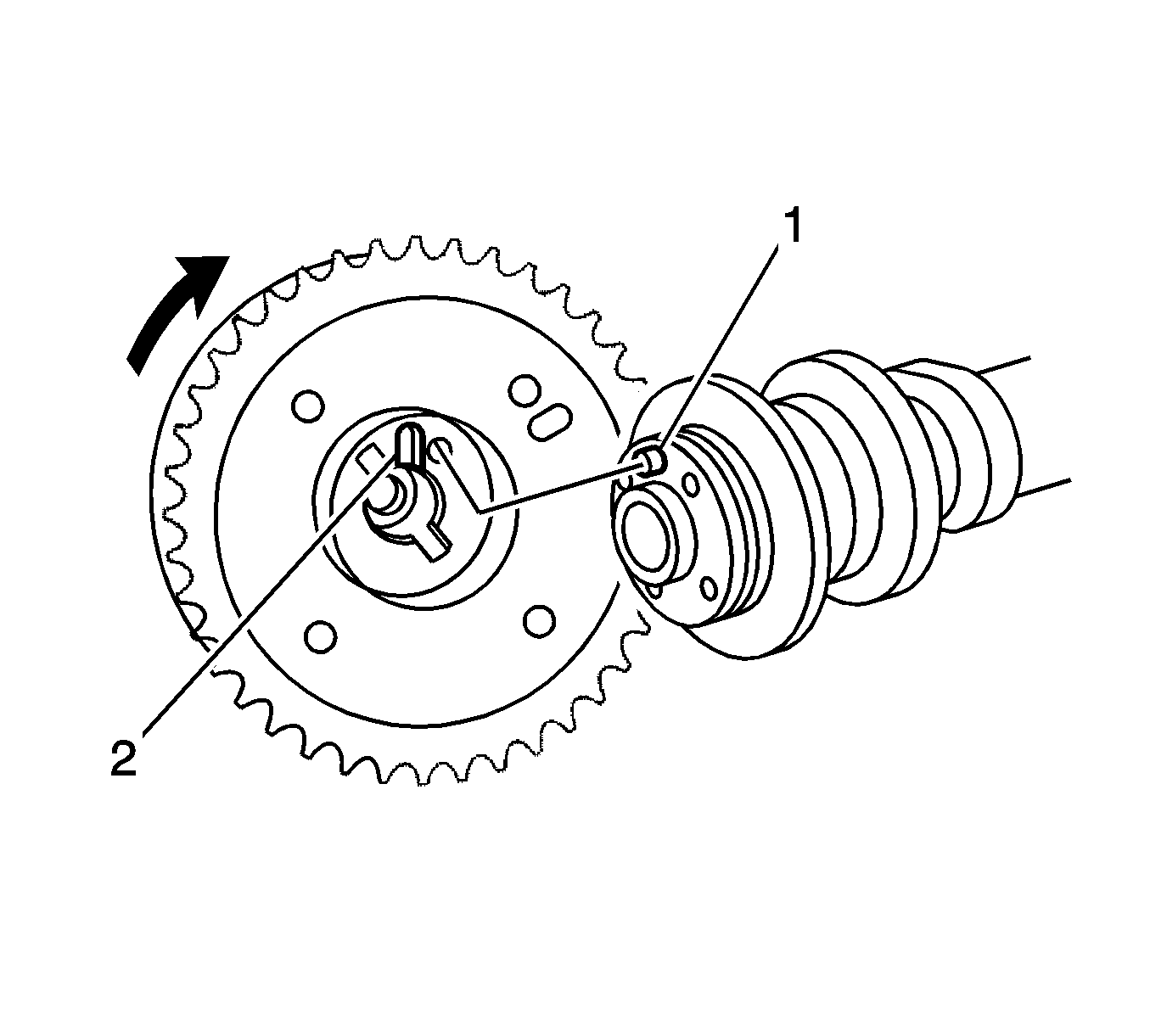
- Install camshaft timing gear assembly by putting the camshaft timing gear and camshaft together with the straight pin (1) and key groove misaligned,
as shown in the illustration.
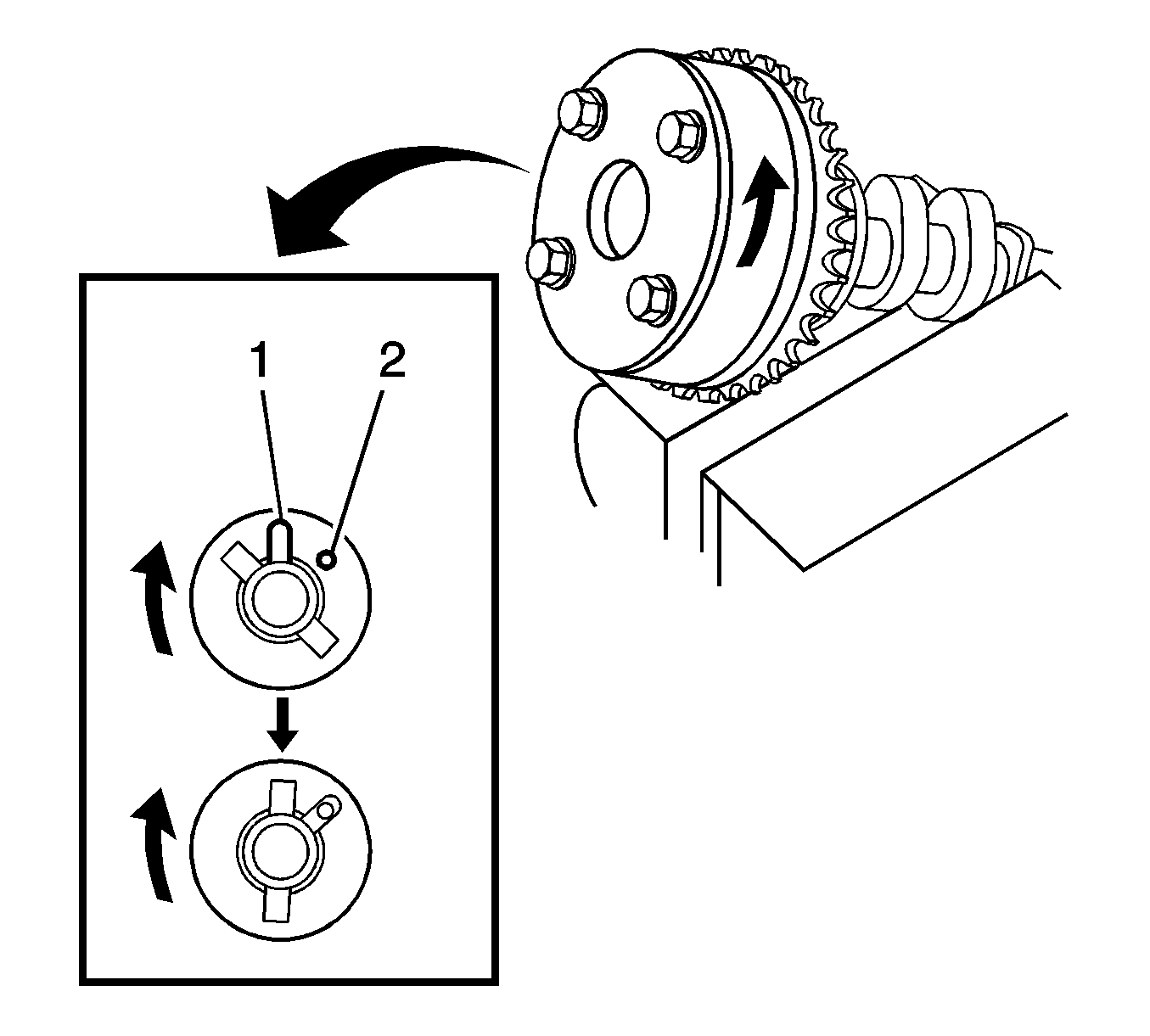
Note: Be sure not to turn the camshaft timing gear to the retard direction (clockwise).
- Turn the camshaft timing gear as shown in the illustration while pushing it gently against the camshaft. Push further at the position where the pin fits (1) into the groove.
- Check that there is no clearance between the gear flange and camshaft.
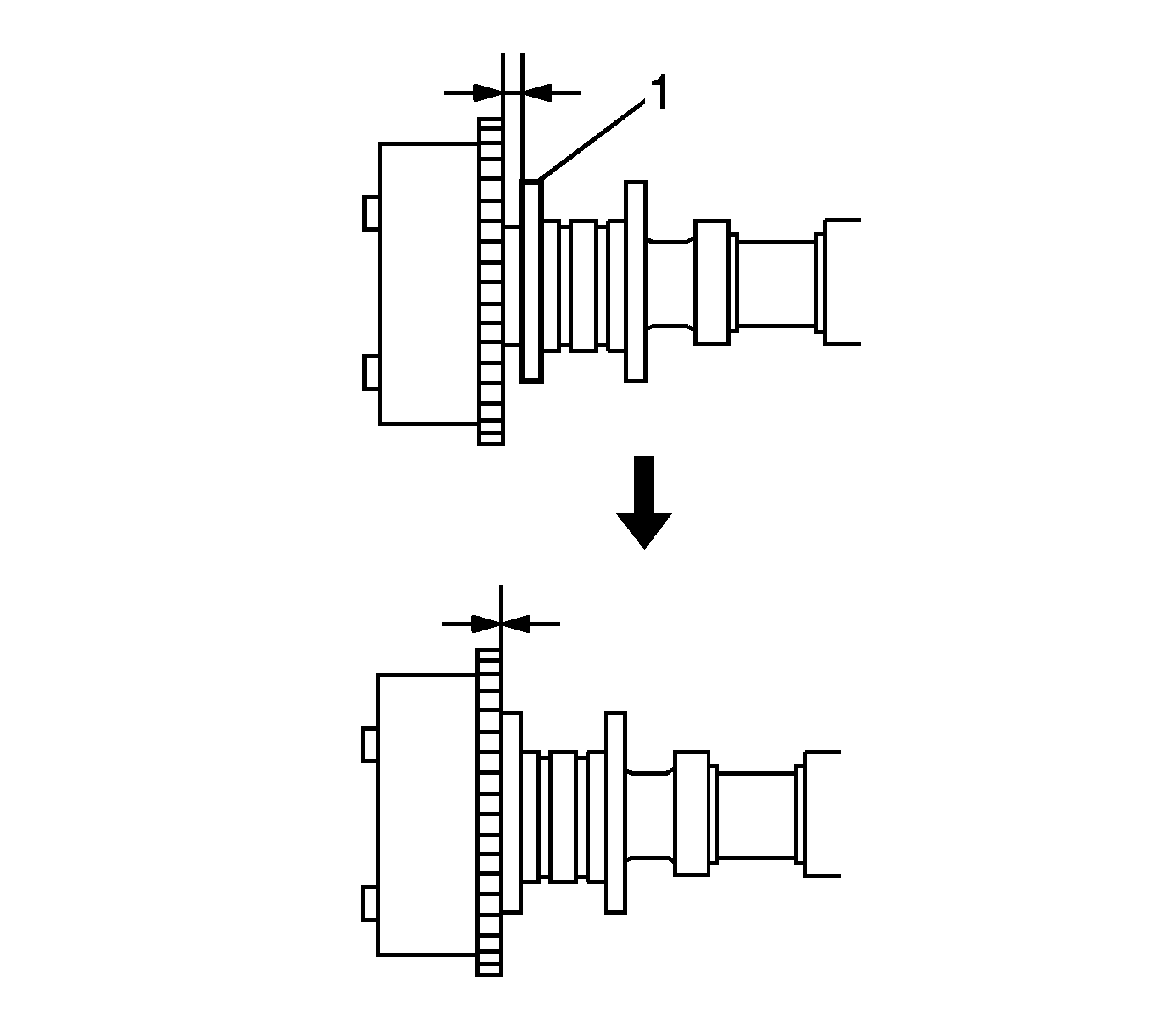
- Check that there is no clearance (1) between the gear flange and camshaft.
Caution: Refer to Fastener Caution in the Preface section.
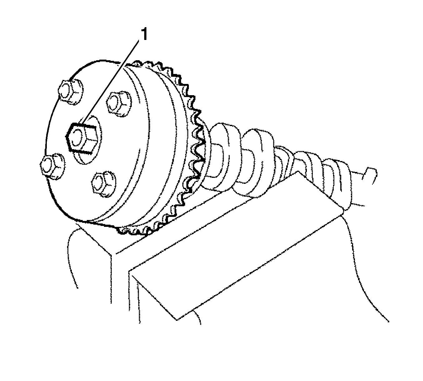
- Install the flange bolt (1) with the camshaft timing gear assembly fixed in place and tighten to
54 N·m (40 lb ft).
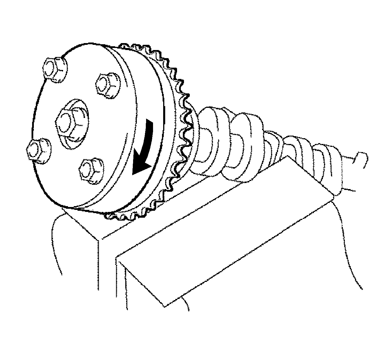
- Check that the camshaft timing gear assembly can move to the retard direction (clockwise) and is locked in the most retarded position.
- Apply a light coat of engine oil to the journal portion of the intake camshaft.
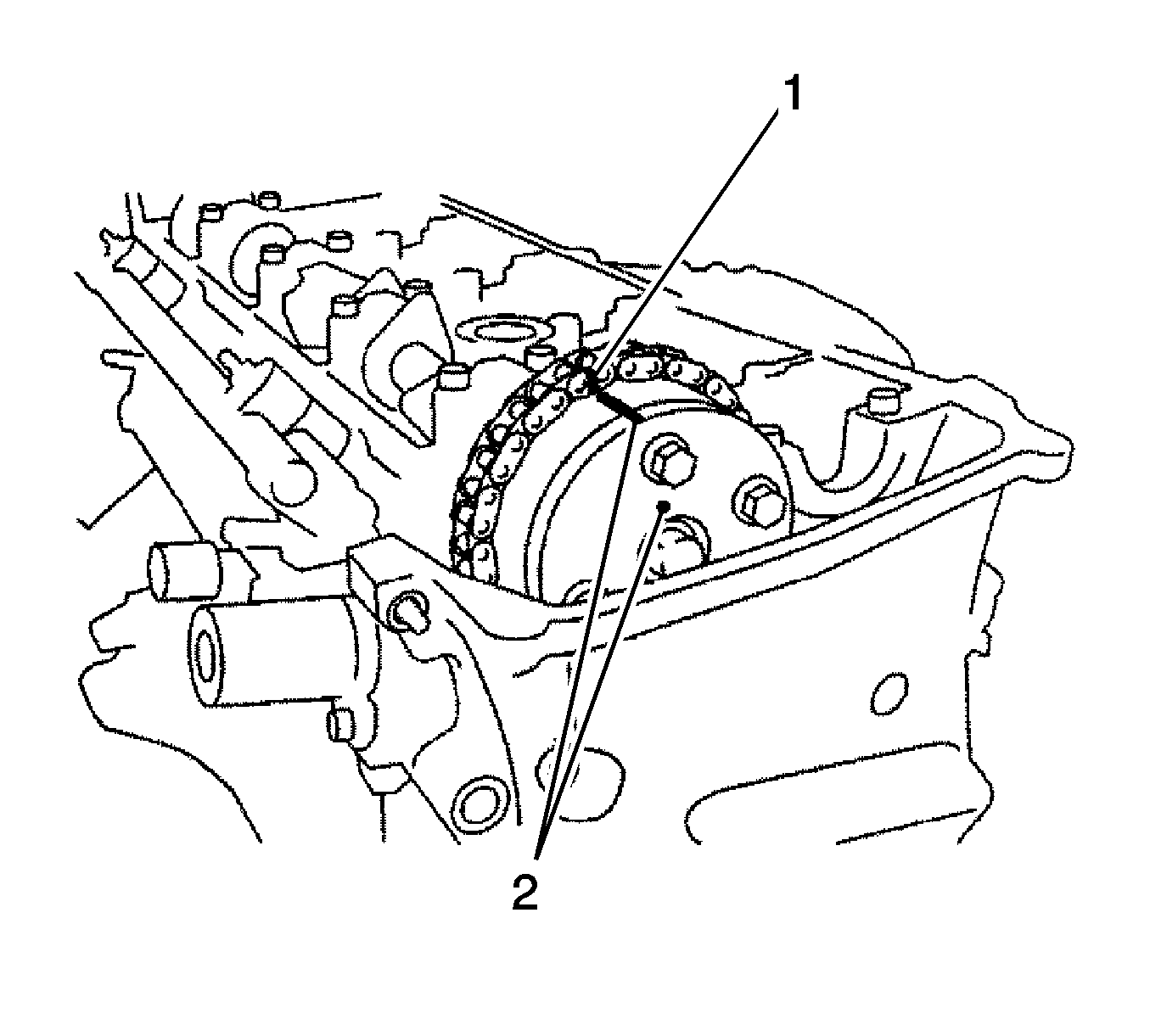
- Install the timing chain onto the camshaft timing gear with the paint mark (1) aligned with the timing mark on the camshaft timing gear as shown in the illustration.
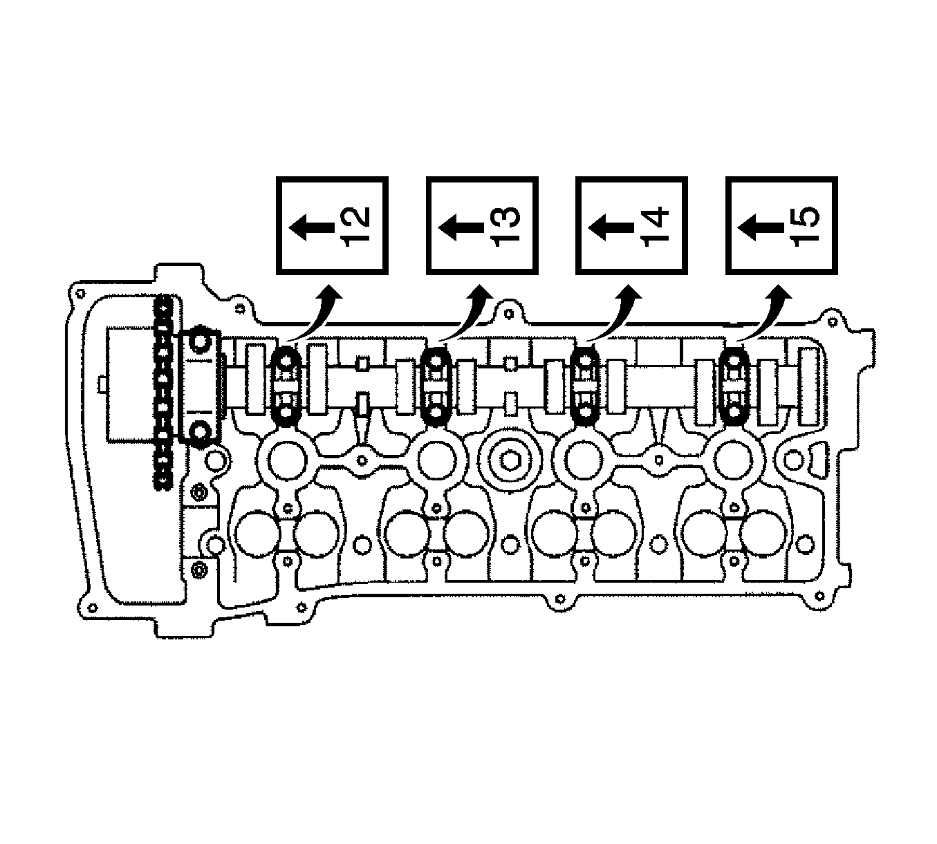
- Examine the front marks and numbers, and check that the order is as shown in the illustration. Then install the bearing caps into the cylinder head.
- Apply a light coat of engine oil on the threads and under the heads of the bearing cap bolts.
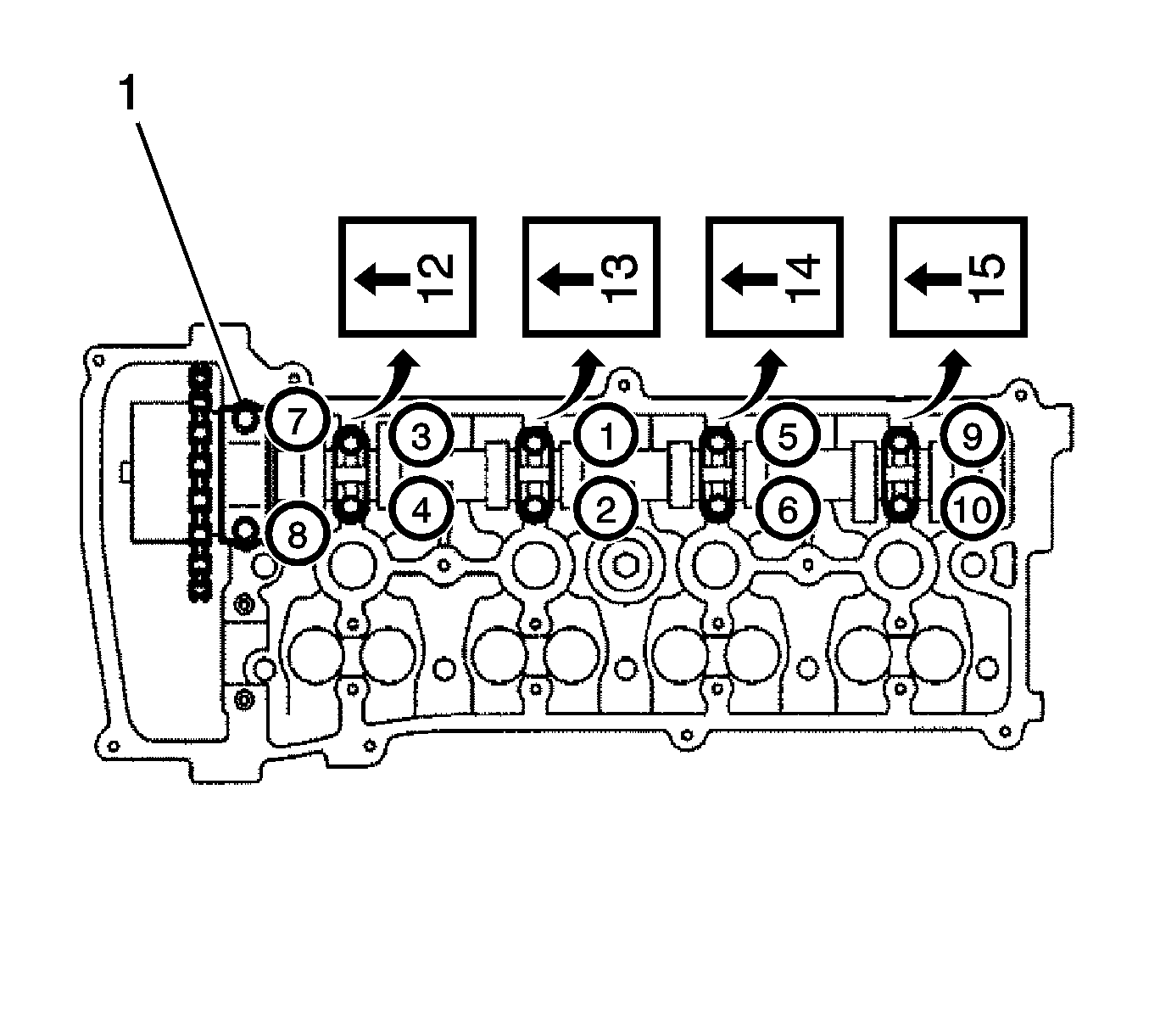
- Using several steps, uniformly install the 10 bearing cap bolts (1) in the sequence shown in the illustration and tighten.
| • | The thrust bearing bolts to
30 N·m (22 lb ft) |
| • | The remaining bearing bolts to
9.0 N·m (80 lb in) |
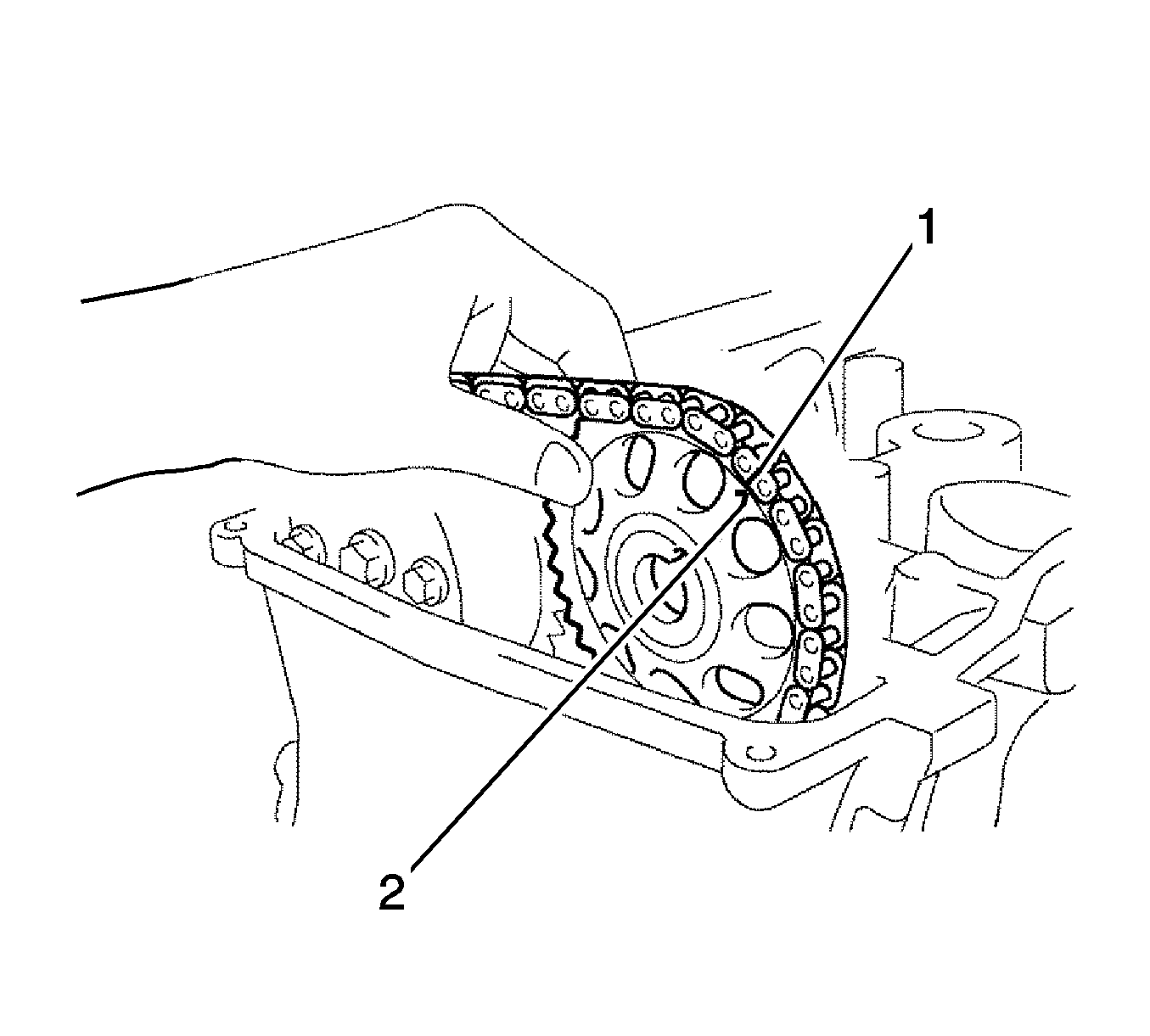
- Install the exhaust camshaft.
| 12.1. | Apply a light coat of engine oil to the journal portion of the exhaust camshaft. |
| 12.2. | Put the exhaust camshaft on the cylinder head with the paint mark (1) on the chain aligned with the timing mark (2) on the camshaft timing sprocket. |
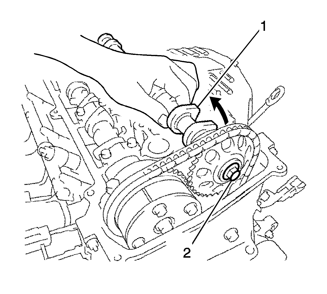
- While holding the exhaust camshaft (1) by hand, temporarily tighten the camshaft timing sprocket set bolt (2).
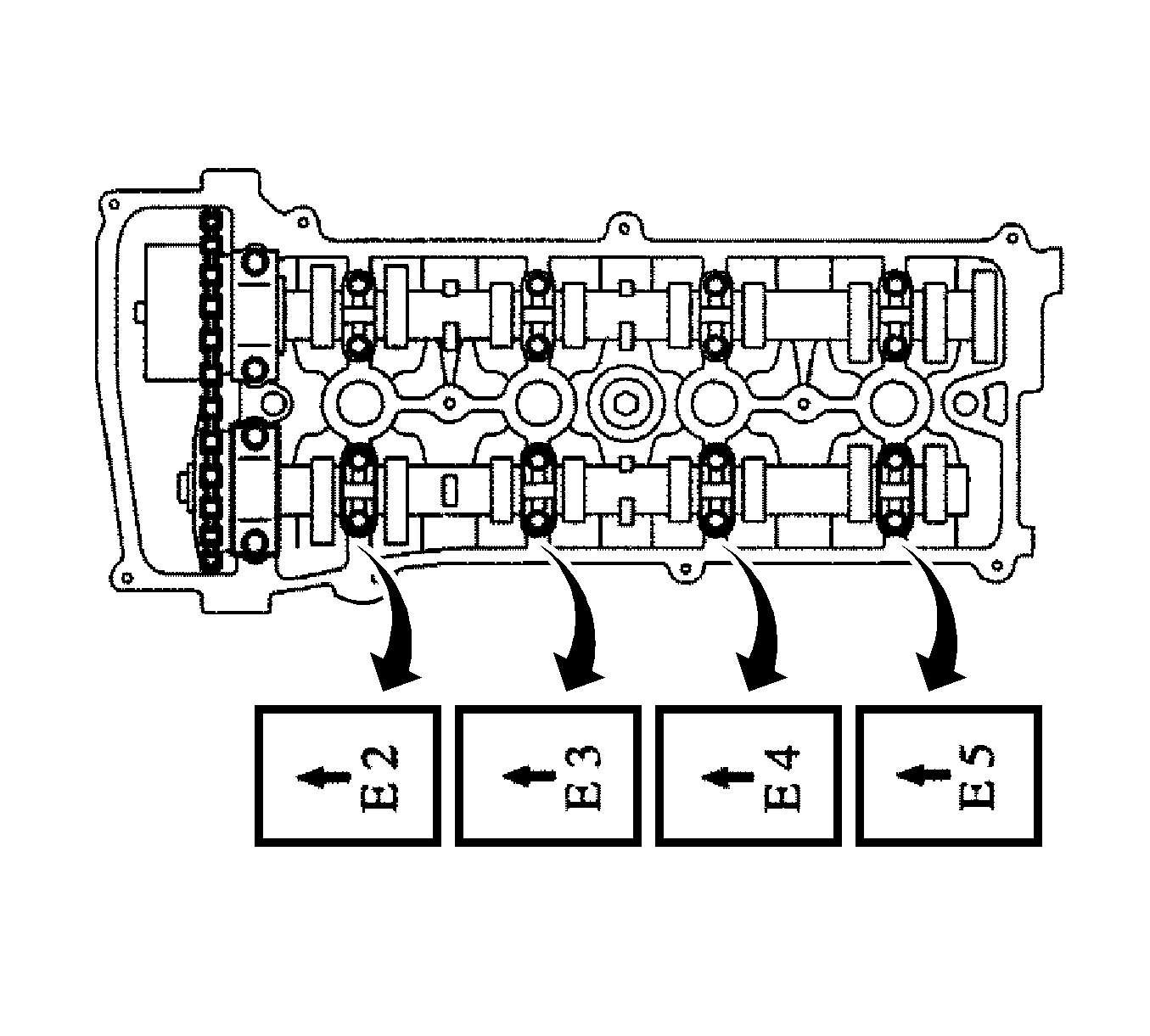
- Examine the front marks and numbers, and check that the order is as shown in the illustration. Then install the bearing caps onto the cylinder head.
- Apply a light coat of engine oil to the threads and under the heads of the bearing cap bolts.
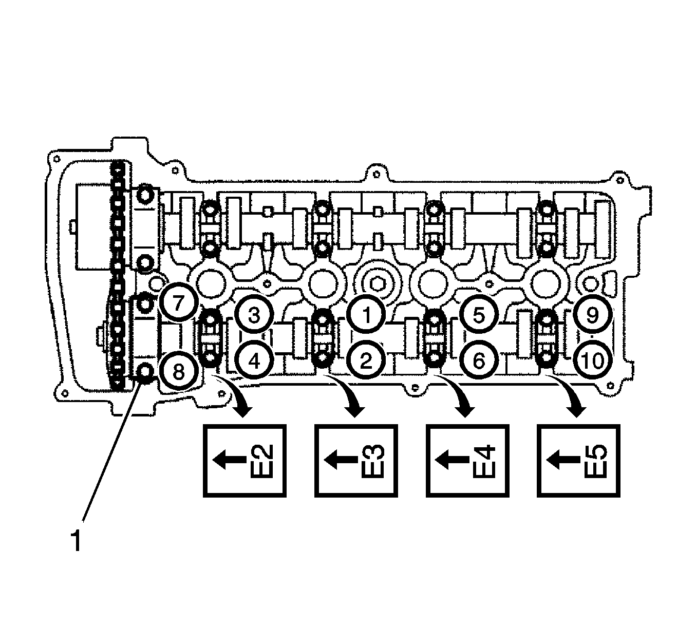
- Using several steps, uniformly install the 10 bearing cap bolts (1) in the sequence shown in the illustration and tighten.
| • | The thrust bearing bolts to
30 N·m (22 lb ft) |
| • | The remaining bearing bolts to
9.0 N·m (80 lb in) |
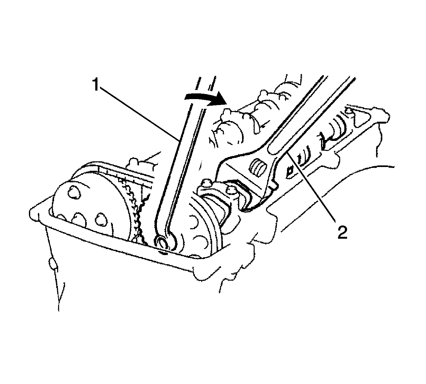
- While holding the exhaust camshaft with a wrench (2), tighten the camshaft timing sprocket set bolt to
54 N·m (40 lb ft).
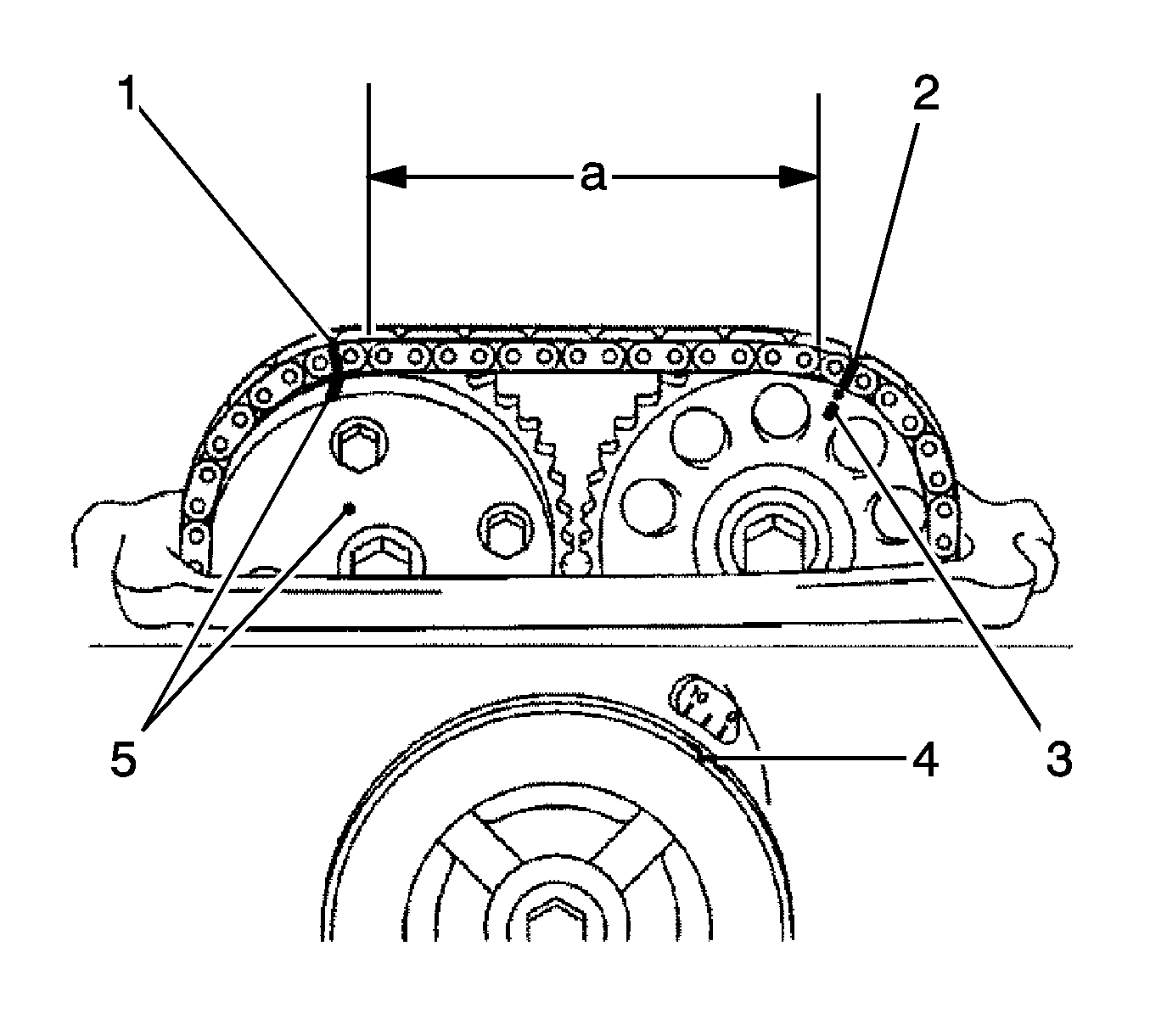
- Check that the paint marks on the chain are aligned with the timing marks (1, 2) on the camshaft timing gear and camshaft timing sprocket. Also,
check that the crankshaft pulley groove (4) is aligned with the timing mark 0 on the timing mark chain cover.
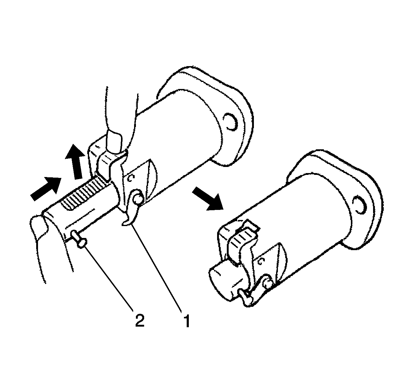
- Install the chain tensioner assembly. Release the ratchet pawl, then fully push in the plunger and hook the hook (1) to the pin (2) so that
the plunger is in the position shown in the illustration.
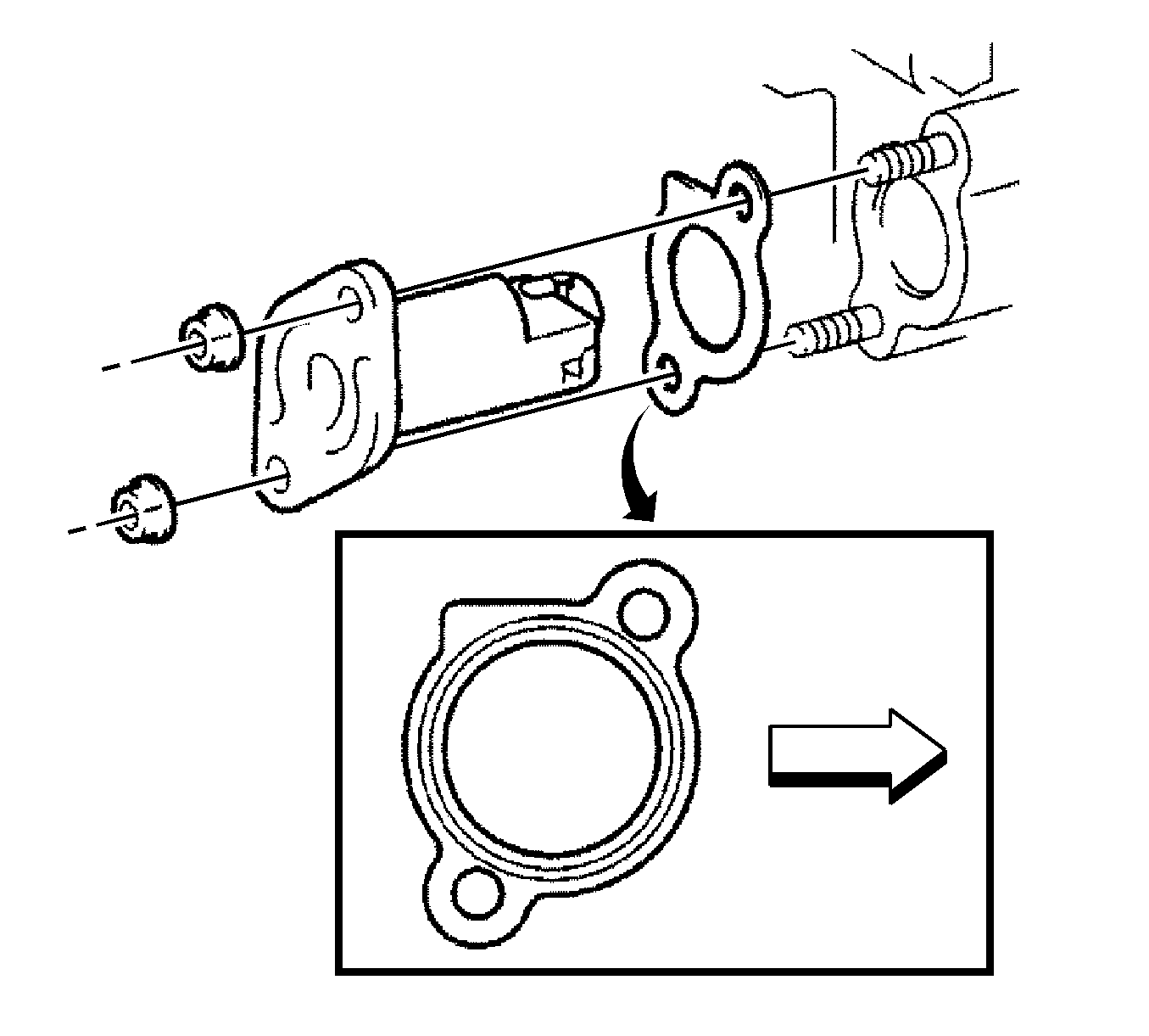
Note: When installing the chain tensioner, set the hook again if the hook releases the plunger.
- Install a new gasket and chain tensioner with the 2 nuts and tighten to
9.0 N·m (80 lb in).
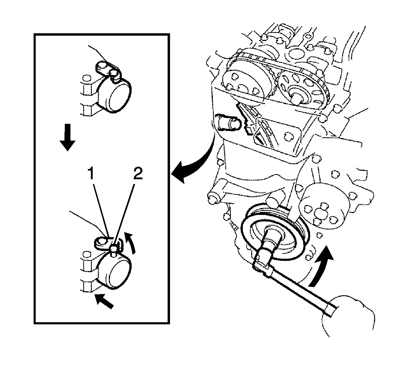
- Turn the crankshaft counterclockwise, then disconnect the plunger knock pin (2) from the hook (1).
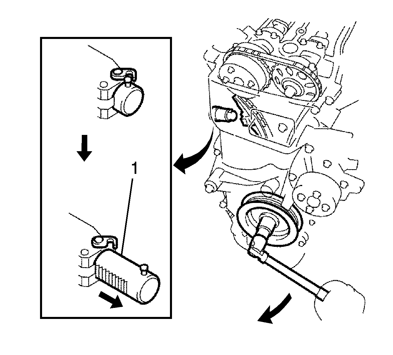
- Turn the crankshaft clockwise, then check that the plunger (1) is extended.
- Set the No. 1 cylinder to TDC/compression.
- Check the valve clearance. Refer to
Valve Clearance Adjustment.
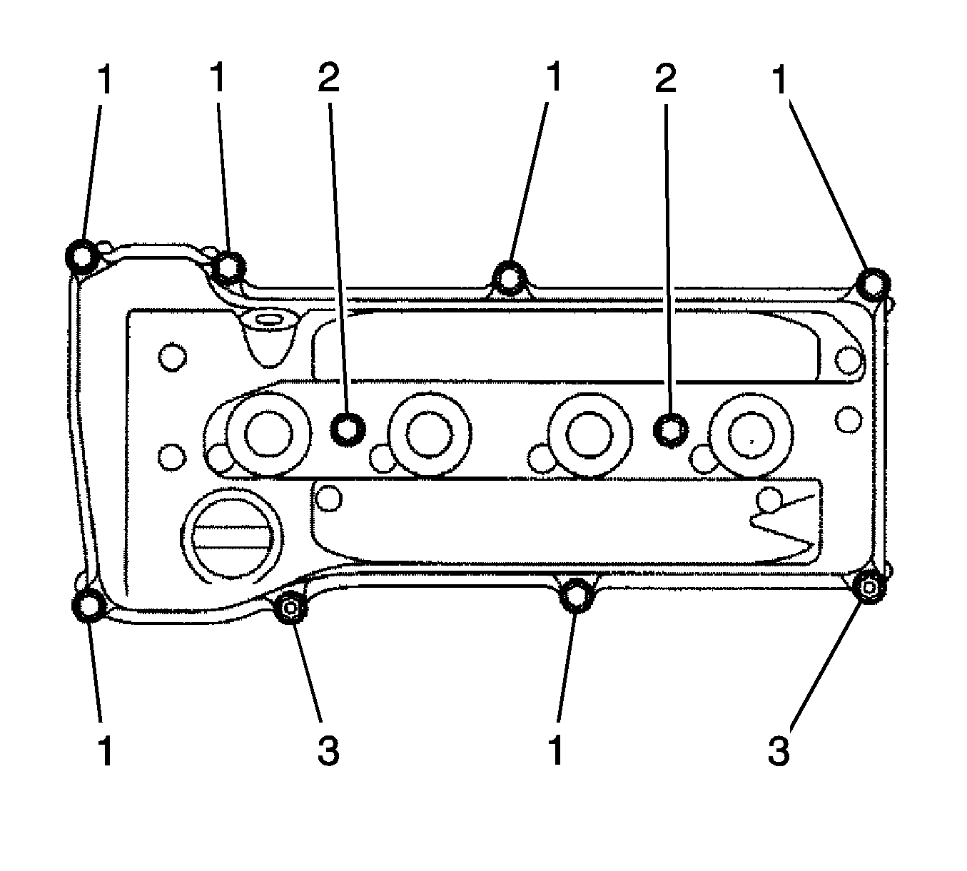
- Remove any old packing material from the contact surface.
- Install the cylinder head cover gasket with the 8 bolts (1) and 2 nuts (3) and tighten.
| • | Bolts 1 to
11 N·m (8 lb ft) |
| • | Bolts 2 to
14 N·m (10 lb ft) |
| • | Nuts to
11 N·m (8 lb ft) |

- Install the 2 engine wire harness brackets with the 2 bolts (1, 2) and tighten to
8.4 N·m (74 lb in).

- Connect the 2 ventilation hoses (1, 2) to the cylinder head cover.
- Install the spark plug. Refer to
Spark Plug Replacement.
- Install the ignition coil assembly. Refer to
Ignition Coil Replacement.
- Inspect for oil leak.
- Inspect the ignition timing.
- Install the engine cover. Refer to
Engine Cover Replacement.
- Install the engine under right cover.


