Electronic Column Lock Module Replacement - On Vehicle Non-Telescoping
Tools Required
J 42640 Steering Column Lock Pin
Removal Procedure
- Remove the upper and lower steering column trim covers. Refer to Steering Column Trim Covers Replacement - On Vehicle .
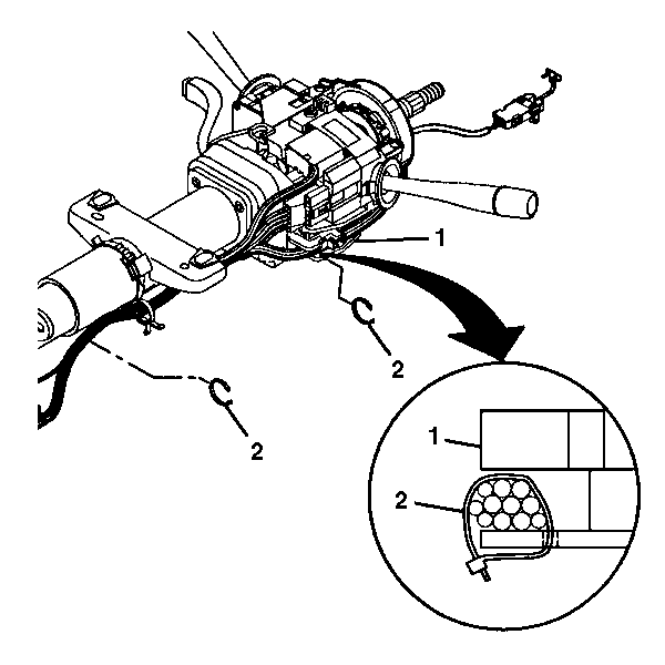
- Remove the wire harness straps (2) from the steering column tilt head assembly (1) and the column.
- Install J 42640 to the steering column.
- Remove the steering column tilt head assembly. Refer to Steering Column Tilt Head Housing - Disassemble - Off Vehicle .
- Remove the electronic column lock module. Refer to Electronic Column Lock Module - Disassemble - Off Vehicle .
Important: If the steering column connectors are disconnected with the ignition in the ON position, the BCM will enter a fail enable mode and prevent steering column lock operation. The PCM will also inhibit vehicle motion by disabling fuel. To clear the BCM fail enable mode, disconnect the BCM fuse #25 for 15 seconds.

Installation Procedure
- Install the electronic column lock module. Refer to Electronic Column Lock Module - Assemble - Off Vehicle .
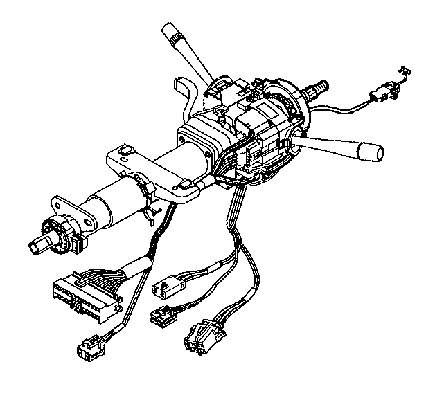
- Route the wire harness assembly along the steering column jacket assembly.
- Remove J 42640 from the steering column.
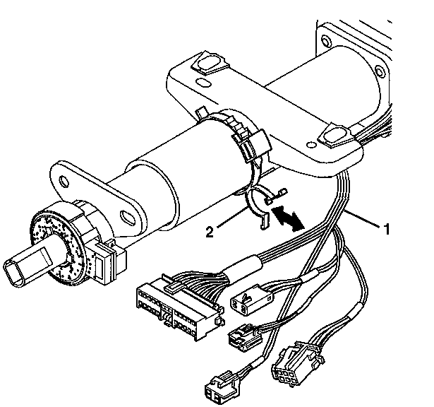
- Install the wire harness assembly (1) into the wire harness strap (2).
- Install new wire harness straps (2) to the steering column assembly (1) and the column.
- Install the steering column tilt head assembly. Refer to Steering Column Tilt Head Housing - Assemble - Off Vehicle .
- Install the upper and lower steering column trim covers. Refer to Steering Column Trim Covers Replacement - On Vehicle .


Electronic Column Lock Module Replacement - On Vehicle Telescoping
Tools Required
J 42640 Steering Column Lock Pin
Removal Procedure
- Remove the upper and lower steering column trim covers. Refer to Steering Column Trim Covers Replacement - On Vehicle .
- Remove the wire harness straps (2) from the steering column tilt head assembly (1) and the column.
- Install J 42640 to the steering column.
- Remove the steering column tilt head assembly. Refer to Steering Column Tilt Head Housing - Disassemble - Off Vehicle .
- Remove the electronic column lock module. Refer to Electronic Column Lock Module - Disassemble - Off Vehicle .
Important: If the steering column connectors are disconnected with the ignition in the ON position, the BCM will enter a fail enable mode and prevent steering column lock operation. The PCM will also inhibit vehicle motion by disabling fuel. To clear the BCM fail enable mode, disconnect the BCM fuse #25 for 15 seconds.

Installation Procedure
- Install the electronic column lock module. Refer to Electronic Column Lock Module - Assemble - Off Vehicle .
- Route the wire harness assembly along the steering column jacket assembly.
- Install the wire harness assembly (1) into the wire harness strap (2).
- Install the steering column tilt head assembly. Refer to Steering Column Tilt Head Housing - Assemble - Off Vehicle .
- Remove J 42640 from the steering column.
- Install the upper and lower steering column trim covers. Refer to Steering Column Trim Covers Replacement - On Vehicle .


