Steering Column Tilt Head Housing - Assemble - Off Vehicle Telescoping
Tools Required
| • | J 42137
Steering Column Lock Plate Compressor Adapter |

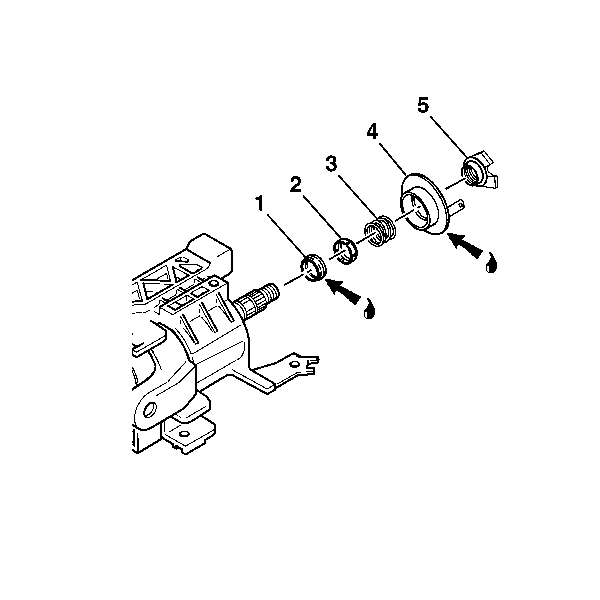
- Lubricate the inner race (1) with synthetic grease.
- Install the inner race (1) onto the steering shaft assembly.
- Install the upper bearing inner race seat (2) onto the steering shaft assembly.
- Install the upper bearing spring (3) onto the steering shaft assembly.
- Lubricate the lower brass surface of the turn signal cancel cam assembly (4) with synthetic grease.
- Install the turn signal cancel cam assembly (4) onto the steering shaft assembly.
- Install the cam orientation plate (5) onto the steering shaft assembly.
- Install the new bearing retainer onto the steering shaft assembly.

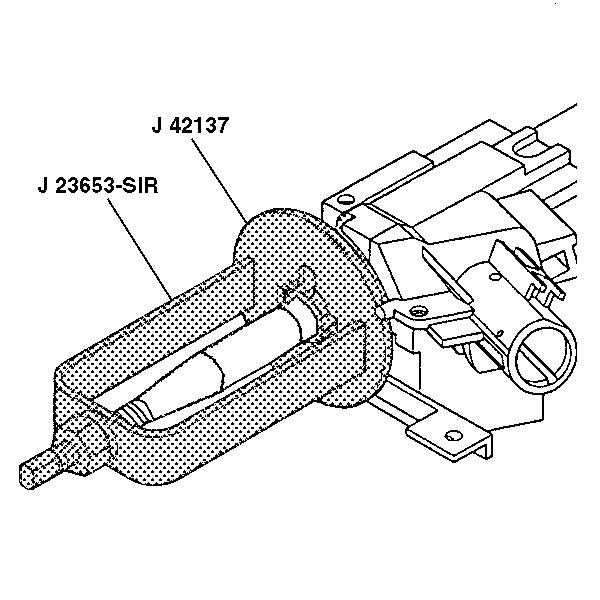
- Compress the cam orientation plate using
J 23653-SIR
and
J 42137
.
- Firmly seat the bearing retainer into the groove on the steering shaft assembly.
- Remove
J 23653-SIR
and
J 42137
.

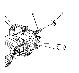
- Install the wave washer (1) to the steering shaft assembly (2).
- Install the inflatable restraint steering wheel module coil. Refer to
Inflatable Restraint Steering Wheel Module Coil Assemble - Off Vehicle
.
- Perform the functional test if equipped with manual transmission or automatic transmission-Europe only. Refer to
Turn Signal Cancel Cam and Steering Shaft Upper Bearing Spring Replacement
steps 6-26.
- Enable the inflatable restraint steering wheel module. Refer to
Enabling the SIR System
in SIR.
Steering Column Tilt Head Housing - Assemble - Off Vehicle Non-Telescoping
Tools Required
| • | J 42137
Steering Column Lock Plate Compressor Adapter |

- Lubricate the inner race (1) with synthetic grease.
- Install the inner race (1) onto the steering shaft assembly.
- Install the upper bearing inner race seat (2) onto the steering shaft assembly.
- Install the upper bearing spring (3) onto the steering shaft assembly.
- Lubricate the lower brass surface of the turn signal cancel cam assembly (4) with synthetic grease.
- Install the turn signal cancel cam assembly (4) onto the steering shaft assembly.
- Install the cam orientation plate (5) onto the steering shaft assembly.
- Install the new bearing retainer onto the steering shaft assembly.

- Compress the cam orientation plate using
J 23653-SIR
and
J 42137
.
- Firmly seat the bearing retainer into the groove on the steering shaft assembly.
- Remove
J 23653-SIR
and
J 42137
.

- Install the wave washer (1) to the steering shaft assembly (2).
- Install the inflatable restraint steering wheel module coil. Refer to
Inflatable Restraint Steering Wheel Module Coil Assemble - Off Vehicle
.
- Perform the functional test if equipped with manual transmission or automatic transmission-Europe only. Refer to
Turn Signal Cancel Cam and Steering Shaft Upper Bearing Spring Replacement
steps 6-26.
- Enable the inflatable restraint steering wheel module. Refer to
Enabling the SIR System
in SIR.


