Cylinder Head Replacement Drivers Side
Removal Procedure
Special Tools
J 36660-A Torque/Angle Meter
- Disconnect the negative battery cable.
- Remove the intake plenum. Refer to Intake Plenum Replacement.
- Remove the intake air resonator. Refer to Intake Air Resonator Replacement.
- Remove the intake manifold. Refer to Intake Manifold Replacement.
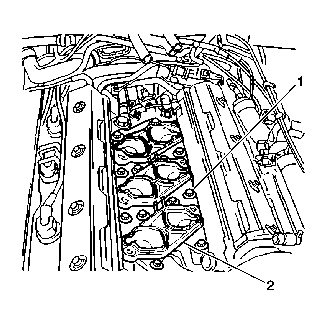
- Remove the intake manifold spacer bolts (1).
- Remove the intake manifold spacer (2).
- Remove the coolant bridge. Refer to Engine Coolant Bridge Replacement.
- Remove the LH valve cover. Refer to Camshaft Cover Replacement.
- Remove the front timing belt cover. Refer to Timing Belt Cover Replacement.
- Remove the timing belt. Refer to Timing Belt Replacement.
- Remove the timing belt tensioner bracket. Refer to Timing Belt Tensioner Pulley Replacement.
- Remove all four of the camshaft gears. Refer to Camshaft Drive Sprocket Replacement.
- Remove the water pump. Refer to Water Pump Replacement.
- Remove the rear timing belt cover. Refer to Timing Belt Rear Cover Replacement.
- Remove the camshaft sensor electrical connection.
- Remove the exhaust camshaft. Refer to Camshaft Replacement.
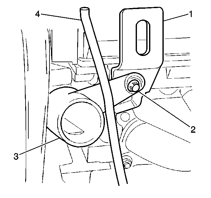
- Remove the coolant pipe/engine lift bracket bolt (2) from the cylinder head.
- Grasp the oil level indicator tube (4) firmly.
- Pull the oil indicator tube upwards to remove the oil indicator tube.
- Remove the upper radiator hose clamp.
- Remove the upper radiator hose from the coolant pipe.
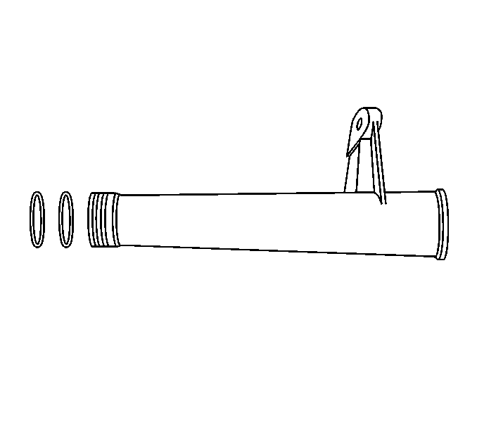
- Twist the coolant intake pipe to remove the coolant intake pipe.
- Pull away the left exhaust manifold from the cylinder head. Refer to Exhaust Manifold Replacement (Driver Side) . The left exhaust manifold will not be completely removed. The manifold must be separated from the cylinder head to allow for the cylinder head removal.
- Remove the ignition coil electrical connection.
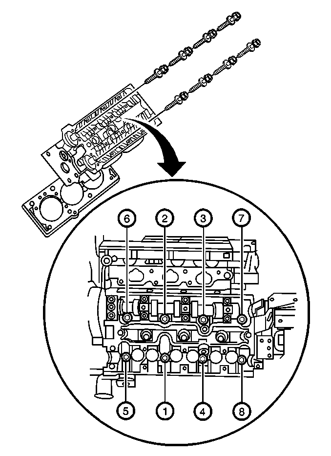
- Use the reverse of the tightening sequence (8, 7, 6, 5, etc.) to loosen the cylinder head bolts in stages.
- Remove the cylinder head bolts.
- Remove the cylinder head.
- Remove the cylinder head gasket.
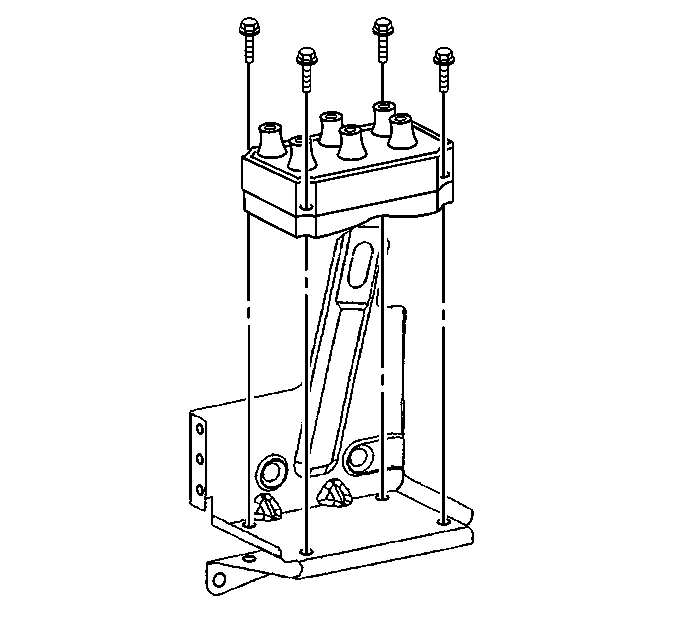
- Remove the ignition coil from the ignition coil bracket to expose the bracket screws.
- Remove the ignition coil bracket.
- Clean and inspect the cylinder head and the sealing surfaces. Refer to Cylinder Head Cleaning and Inspection.
Caution: Refer to Battery Disconnect Caution in the Preface section.
Installation Procedure
- Install the ignition coil bracket to the cylinder head.
- Install the ignition coil to the ignition coil bracket.
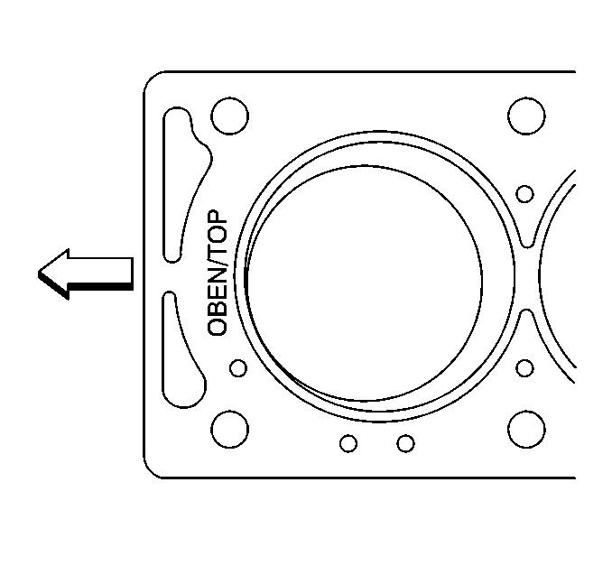
- Install the new cylinder head gasket with OBEN/TOP imprint toward the front of the engine.
- Install the cylinder head to the engine block ensuring adequate clearance from all wires, components, etc.
- Install the new cylinder head bolts.
- Install the ignition coil electrical connection.
- Install the left exhaust manifold to the cylinder head. Refer to Exhaust Manifold Replacement (Driver Side) .
- Replace the two sealing rings on the coolant pipe.
- Lubricate the two sealing rings with coolant.
- Install the coolant pipe.
- Install the upper radiator hose to the coolant pipe.
- Install the upper radiator hose clamp.
- Install the oil level indicator tube (4).
- Install the coolant pipe/engine lift bracket bolt (2) to the cylinder head. Ensure the bolt passes through all attached components.
- Install the exhaust camshaft. Refer to Camshaft Replacement.
- Install the exhaust camshaft sensor electrical connection.
- Install the rear timing belt cover. Refer to Timing Belt Rear Cover Replacement.
- Install the water pump. Refer to Water Pump Replacement.
- Install all four of the camshaft gears. Refer to Camshaft Drive Sprocket Replacement.
- Install the timing belt tensioner bracket. Refer to Timing Belt Tensioner Pulley Replacement.
- Install the timing belt. Refer to Timing Belt Replacement.
- Install the front timing belt cover. Refer to Timing Belt Cover Replacement.
- Install the LH valve cover. Refer to Camshaft Cover Replacement.
- Install the coolant bridge. Refer to Engine Coolant Bridge Replacement.
- Install the intake manifold spacer (2).
- Install the intake manifold spacer bolts (1).
- Install the intake manifold. Refer to Intake Manifold Replacement.
- Install the intake air resonator. Refer to Intake Air Resonator Replacement in Engine Controls.
- Install the intake plenum. Refer to Intake Plenum Replacement.
- Reconnect the negative battery cable and reprogram the applicable accessories.
Notice: Refer to Fastener Notice in the Preface section.

Important: Use new cylinder head bolts. The required tightening method stretches the bolts, therefore the cylinder head bolts are not reusable.
Tighten
Use the
J 36660-A
and the proper tightening sequence (1, 2, 3, etc.) to tighten the cylinder head bolts, in stages, to 25 N·m (18 lb ft) plus
90 degrees, plus 90 degrees, plus 90 degrees, plus 15 degrees.


Tighten
Tighten the coolant pipe/engine lift bracket bolt to the cylinder head to 20 N·m (15 lb ft).

Tighten
Tighten the intake manifold spacer bolts in a spiral direction, starting from the inside and working outward, to 20 N·m (15 lb ft).
Cylinder Head Replacement Passenger Side
Removal Procedure
Special Tools
J 36660-A Torque/Angle Meter
- Disconnect the negative battery cable.
- Remove the intake plenum. Refer to Intake Plenum Replacement.
- Remove the intake air resonator. Refer to Intake Air Resonator Replacement.
- Remove the intake manifold. Refer to Intake Manifold Replacement.
- Remove the intake manifold spacer bolts (1).
- Remove the intake manifold spacer (2).
- Remove the coolant bridge. Refer to Engine Coolant Bridge Replacement.
- Remove the RH valve cover. Refer to Camshaft Cover Replacement
- Remove the front timing belt cover. Refer to Timing Belt Cover Replacement
- Remove the timing belt. Refer to Timing Belt Replacement.
- Remove the timing belt tensioner bracket. Refer to Timing Belt Tensioner Pulley Replacement.
- Remove all four of the camshaft gears. Refer to Camshaft Drive Sprocket Replacement.
- Remove the water pump. Refer to Water Pump Replacement.
- Remove the rear timing belt cover. Refer to Timing Belt Rear Cover Replacement.
- Remove the exhaust camshaft. Refer to Camshaft Replacement.
- Remove the coolant intake pipe. Refer to Engine Coolant Inlet Pipe Replacement.
- Pull away the right side exhaust manifold from the cylinder head. Refer to Exhaust Manifold Replacement (Passenger Side) .
- Use the REVERSE of the tightening sequence (8, 7, 6, etc.) to loosen the cylinder head bolts in stages.
- Remove the cylinder head bolts.
- Remove the cylinder head.
- Remove the cylinder head gasket.
- Clean and inspect the cylinder head and the sealing surfaces. Refer to Cylinder Head Cleaning and Inspection.
Caution: Refer to Battery Disconnect Caution in the Preface section.

Important: The exhaust manifold will not be completely removed, it must be separated from the cylinder head to allow for the cylinder head removal clearances.

Installation Procedure
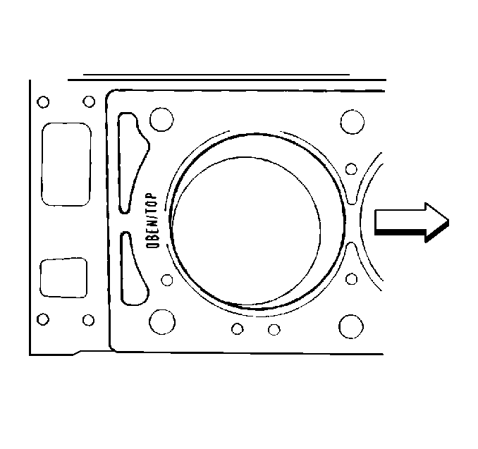
- Install the new cylinder head gasket with OBEN/TOP imprint toward the rear of the engine.
- Install the cylinder head to the engine block ensuring adequate clearance from all wires, components, etc.
- Install the new cylinder head bolts.
- Install the right side exhaust manifold to the cylinder head. Refer to Exhaust Manifold Replacement (Passenger Side) .
- Install the coolant intake pipe. Refer to Engine Coolant Inlet Pipe Replacement
- Install the exhaust camshaft. Refer to Camshaft Replacement.
- Install the rear timing belt cover. Refer to Timing Belt Rear Cover Replacement.
- Install the water pump. Refer to Water Pump Replacement.
- Install all four of the camshaft gears. Refer to Camshaft Drive Sprocket Replacement.
- Install the timing belt tensioner bracket. Refer to Timing Belt Tensioner Pulley Replacement.
- Install the timing belt. Refer to Timing Belt Replacement.
- Install the front timing belt cover. Refer to Timing Belt Cover Replacement.
- Install the RH valve cover. Refer to Camshaft Cover Replacement.
- Install the coolant bridge. Refer to Engine Coolant Bridge Replacement.
- Install the intake manifold spacer (2).
- Install the intake manifold spacer bolts (1).
- Install the intake manifold. Refer to Intake Manifold Replacement.
- Install the intake air resonator. Refer to Intake Air Resonator Replacement.
- Install the intake plenum. Refer to Intake Plenum Replacement.
- Reconnect the negative battery cable and reprogram the applicable accessories.
Notice: Refer to Fastener Notice in the Preface section.

Important: Use new cylinder head bolts. The required tightening method stretches the bolts, therefore the cylinder head bolts are not reusable.
Tighten
Use the
J 36660-A
and the proper tightening sequence to tighten the cylinder head bolts, in stages, to 25 N·m (18 lb ft) plus 90 degrees,
plus 90 degrees, plus 90 degrees, plus 15 degrees.

Tighten
Tighten the intake manifold spacer bolts in a spiral direction, starting from the inside and working outward, to 20 N·m (15 lb ft).
