Tools Required
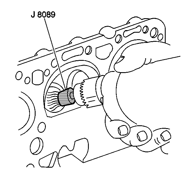
- Use the J 8089
to clean the carbon from the combustion
chambers and from the valves.
- Clean the valve guides.
- Use a buffing wheel to clean the valve stems and valve heads.
- Clean the cylinder head.
- Clean the engine block gasket surfaces.
- Clean the bolt hole threads in the cylinder head and in the engine
block.
- Cracks in the cylinder head usually occur between the exhaust
valves or between the exhaust valve and the spark plug hole. Inspect for the
following in the cylinder head:
| • | Inspect for cracks in the exhaust ports. |
| • | Inspect for cracks in the combustion chambers. |
| • | Inspect for external cracks to the water chamber. |
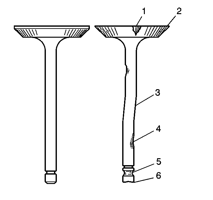
- Inspect the valves for
the following:
| • | Inspect for burned heads (1). |
| • | Inspect for cracked faces (2). |
| • | Inspect for damaged stems (3, 4). |
- Inspect the valve seats for cracks.
- Inspect the valve seats for looseness.
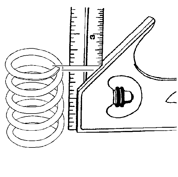
- Perform the following
steps to inspect the valve springs for squareness:
| • | Place the valve spring on a level surface next to a square. |
| • | Rotate the valve spring. |
| • | Replace the valve spring if the valve spring is more than 1.58 mm
(0.062 in) out of square. |
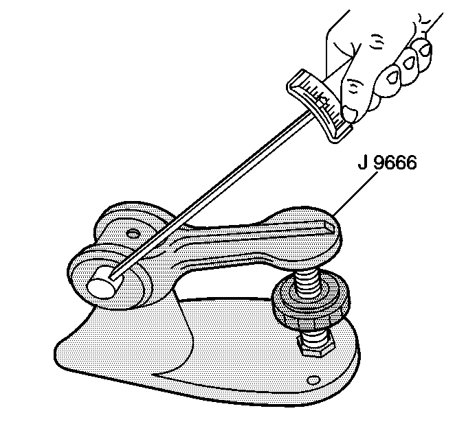
- Use the J 9666
to inspect the valve spring tension.
- Replace the spring if the spring length is less than 34 mm
(1.338 in) when subjected to a compressive force of 252 N·m
(56.6 lb).
- Perform the following
steps to inspect the valve stem-to-valve guide clearance:
| 14.1. | Clamp the J 8001
on the exhaust port side of the cylinder head. |
| 14.2. | Locate the indicator so that the movement of the valve stem from
side to side (crosswise to cylinder head) will cause a direct movement of
the dial indicator stem. |
| 14.3. | Measure the valve head with the valve protruding 10 mm
(0.39 in) from the seat. |
| 14.4. | Drop the valve head about 10 mm (0.393 in) off the
valve seat. |
| 14.5. | Use light pressure to move the stem of the valve from side to
side to obtain a clearance reading. |
| 14.6. | The intake valve clearance should be 0.030 - 0.057 mm
(0.0011 - 0.0022 in). |
| 14.7. | The exhaust valve clearance should be 0.040 - 0.067 mm
(0.0015 - 0.0026 in). |
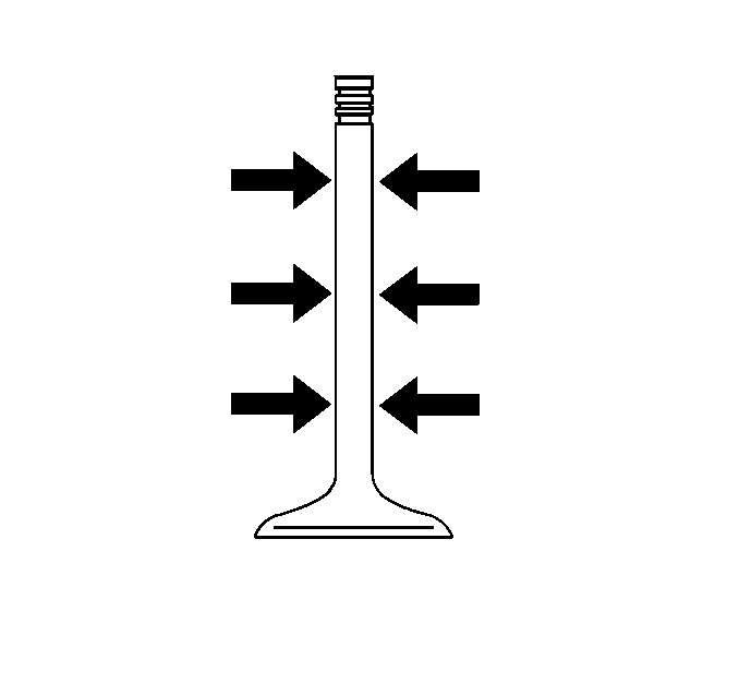
- If the valve clearance is out of specifications, measure the valve
stem in three locations shown in the illustration.
- Compare the lowest measurement to the specifications below:
| • | Intake valve stem: 5.955 - 5.970 mm
(0.2344 - 0.2350 in). |
| • | Exhaust valve stem: 5.945 - 5.960 mm
(0.2340 - 0.2346 in). |
- If the valve stem diameter is out of specification, replace the
valve.
- If the valve stem is within the specifications, the valve guide
is worn.
| • | The valve guide can be reamed oversize. |
| • | If the valve guide is reamed oversize, an oversize valve must
be installed. |


