Removal Procedure
- Remove the engine assembly with transaxle. Refer to
Engine Replacement
- Remove the starter assembly. Refer to
Starter Replacement
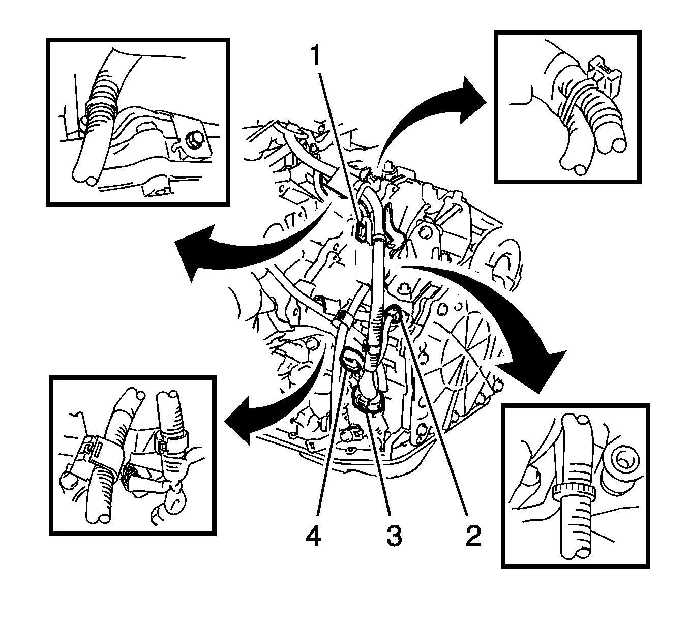
- Disconnect the wire harness.
| • | Disconnect the park/neutral position switch connector. |
| • | Disconnect the transmission wire connector. |
| • | Disconnect the speed sensor connectors (2, 4). |
| • | Disconnect the wire harness clamps. |
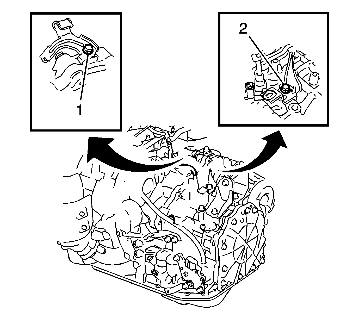
- Remove the bolt and wire harness bracket.
- Remove the bolt (1) and transmission control cable support.
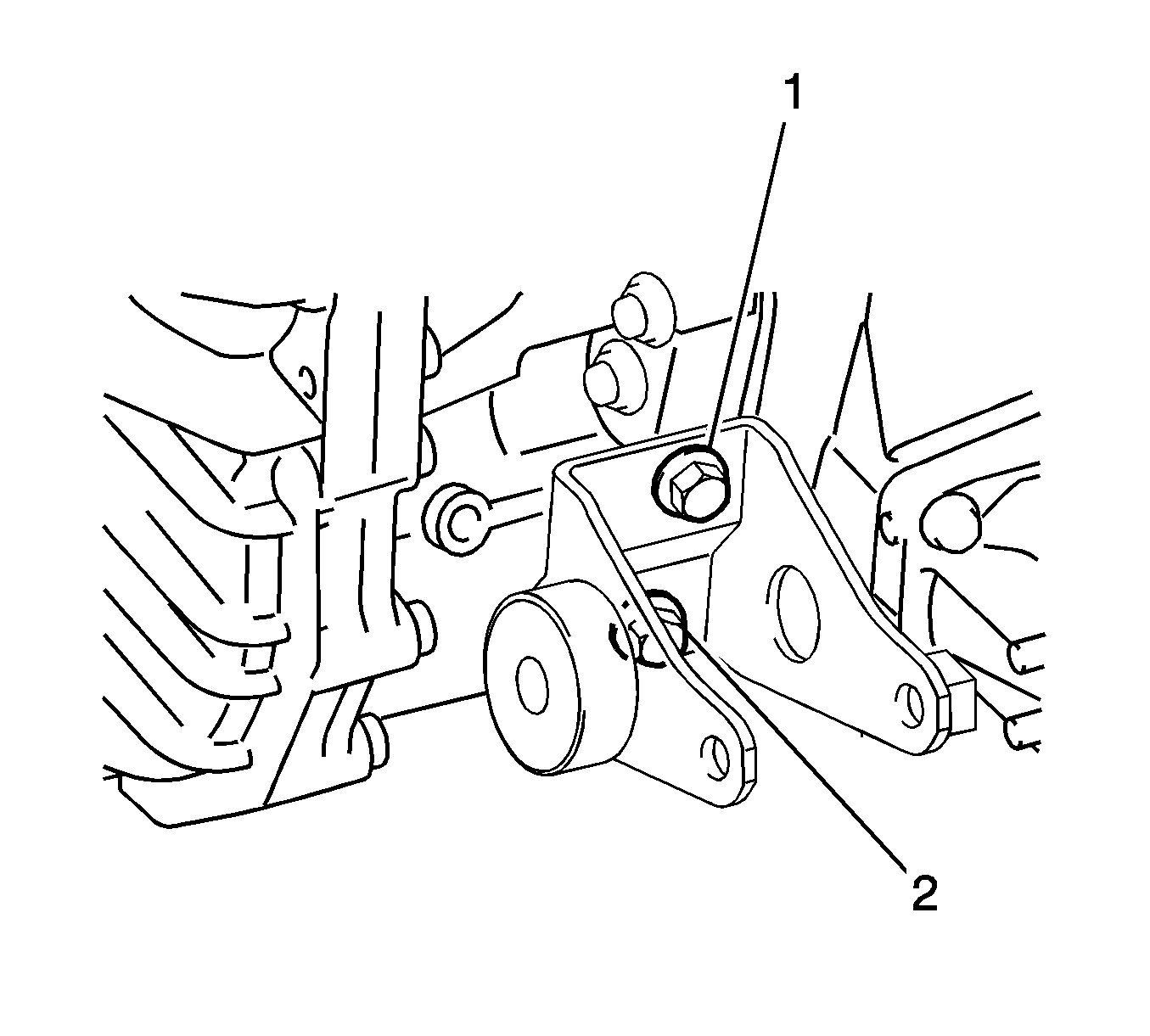
- Remove the bolts (1, 2) and mounting bracket.
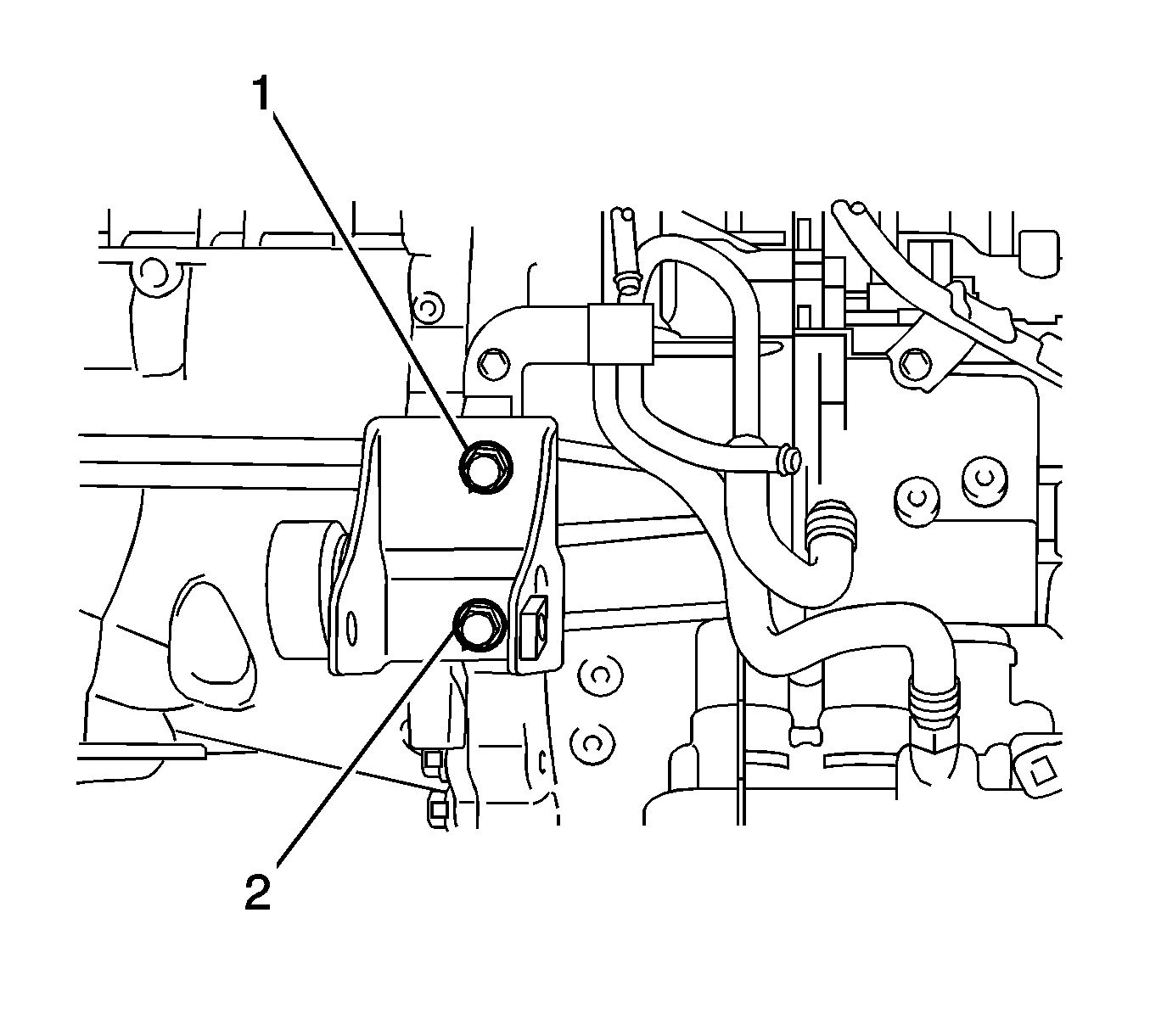
- Remove the bolts (1, 2) and mounting bracket.
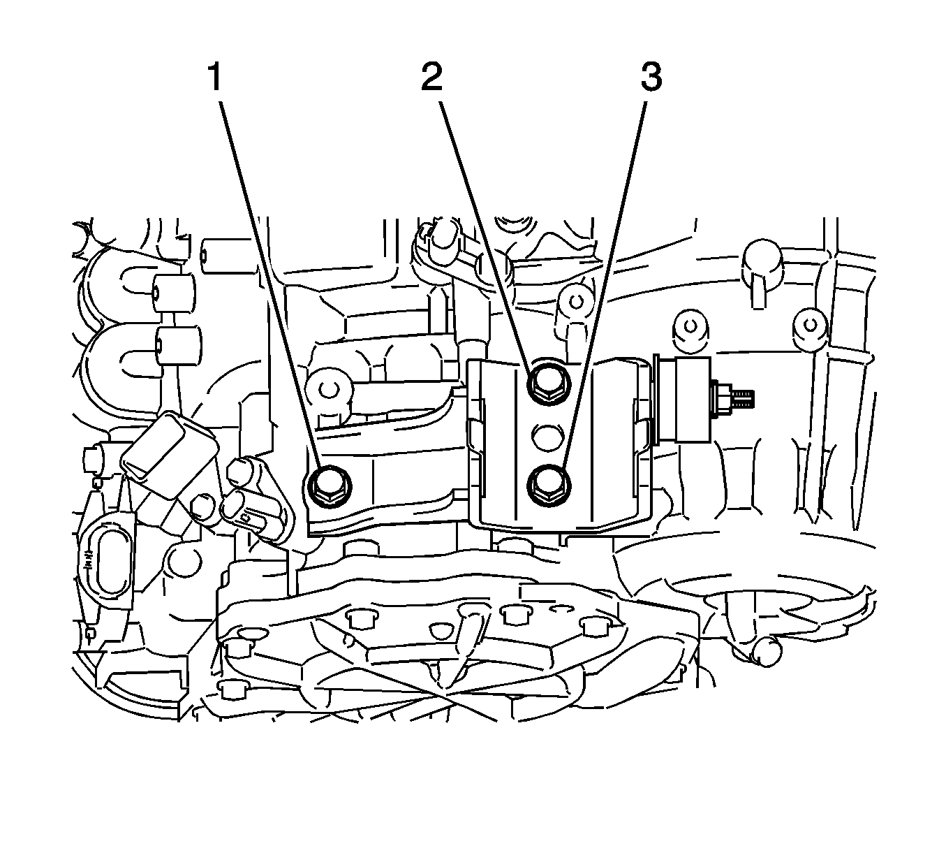
- Remove the bolts (1, 2, 3) and mounting bracket.
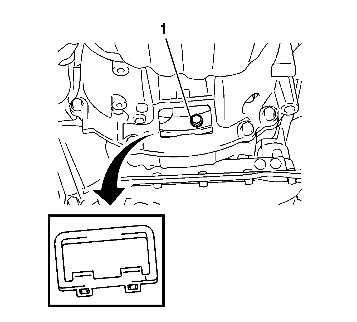
- Remove the flywheel housing under cover.
Note: One of the six bolts has a different color than the other ones.
- Turn the crankshaft to gain access and remove the bolts (1) while holding the crankshaft pulley bolt with a wrench.
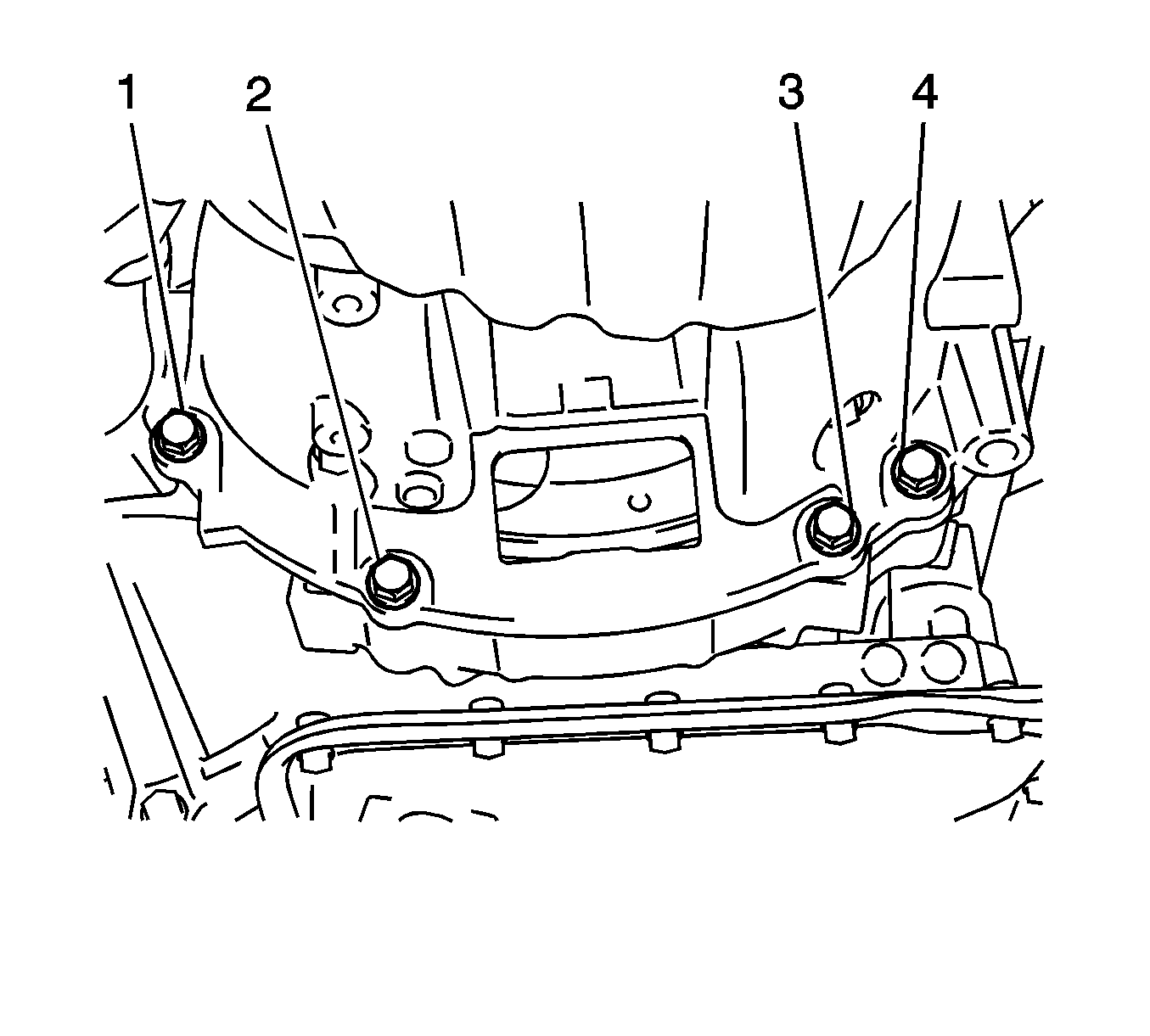
- Remove the lower side mounting bolts (1, 2, 3, 4).
- Remove the upper side mounting bolts.
- Separate and remove the automatic transaxle.
- Remove the transfer stiffener plate - right side.
- Remove the transfer case assembly. Refer to
Transfer Case Assembly Replacement.
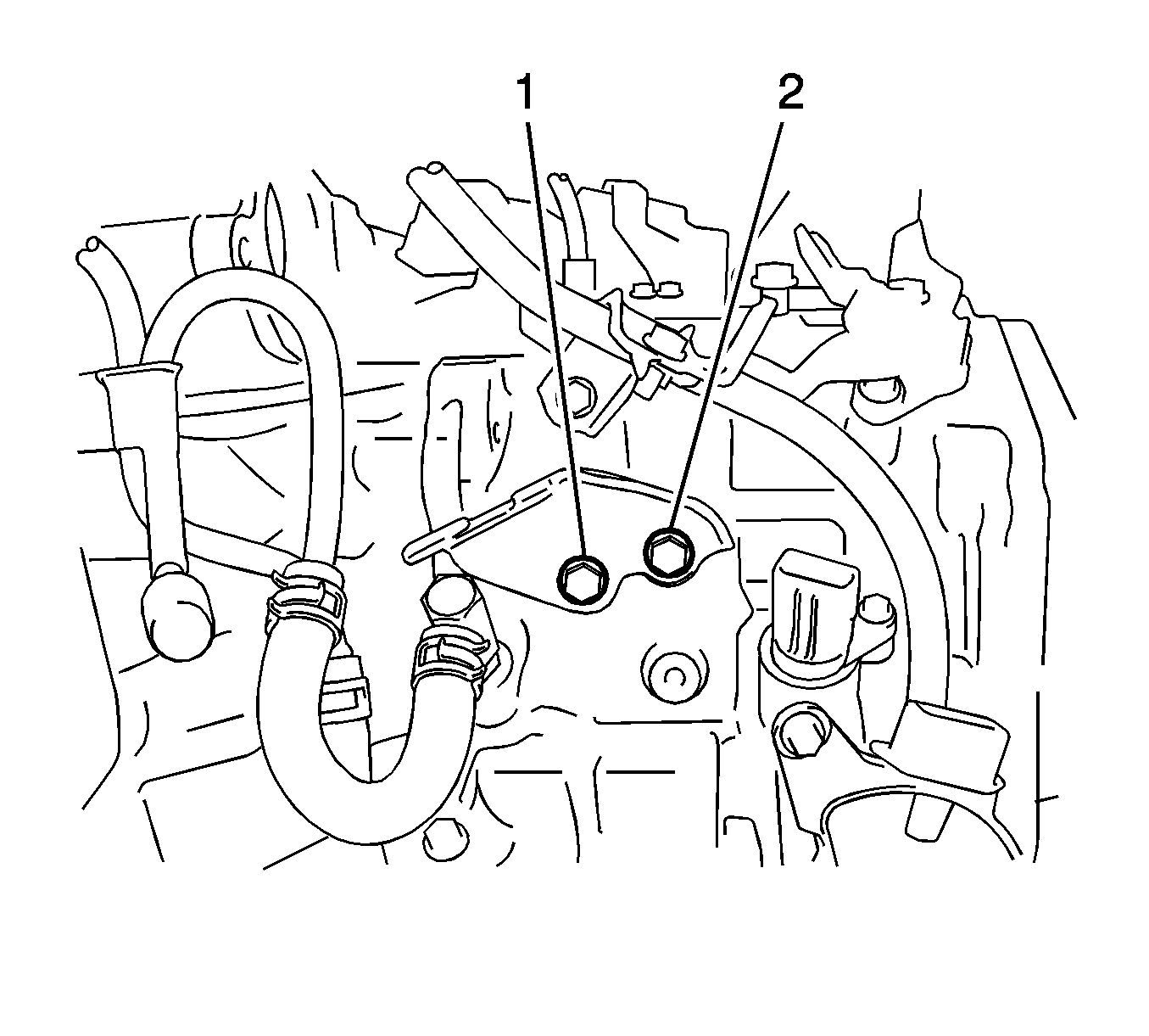
- Remove the bolts (1, 2) and No. 1 transmission control cable bracket.
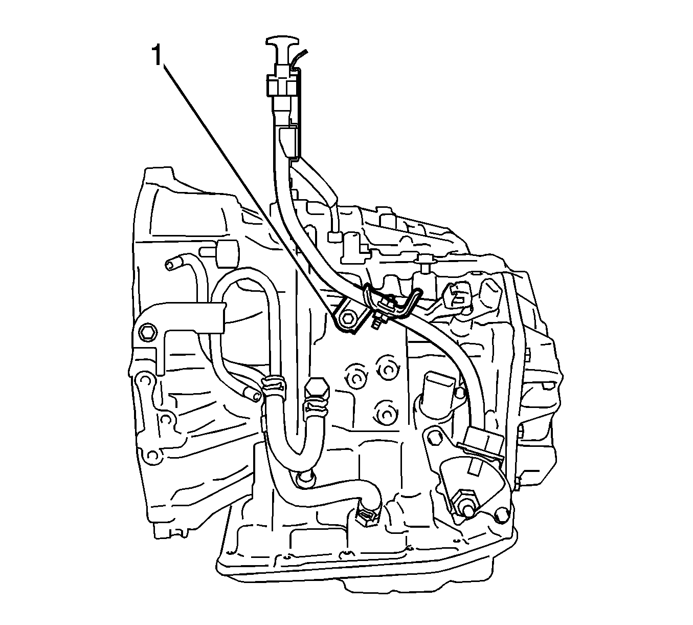
- Remove the transmission oil level indicator.
- Remove the bolt and remove the transmission oil level indicator tube (1).
- Remove the O-ring from the transmission oil level indicator tube.
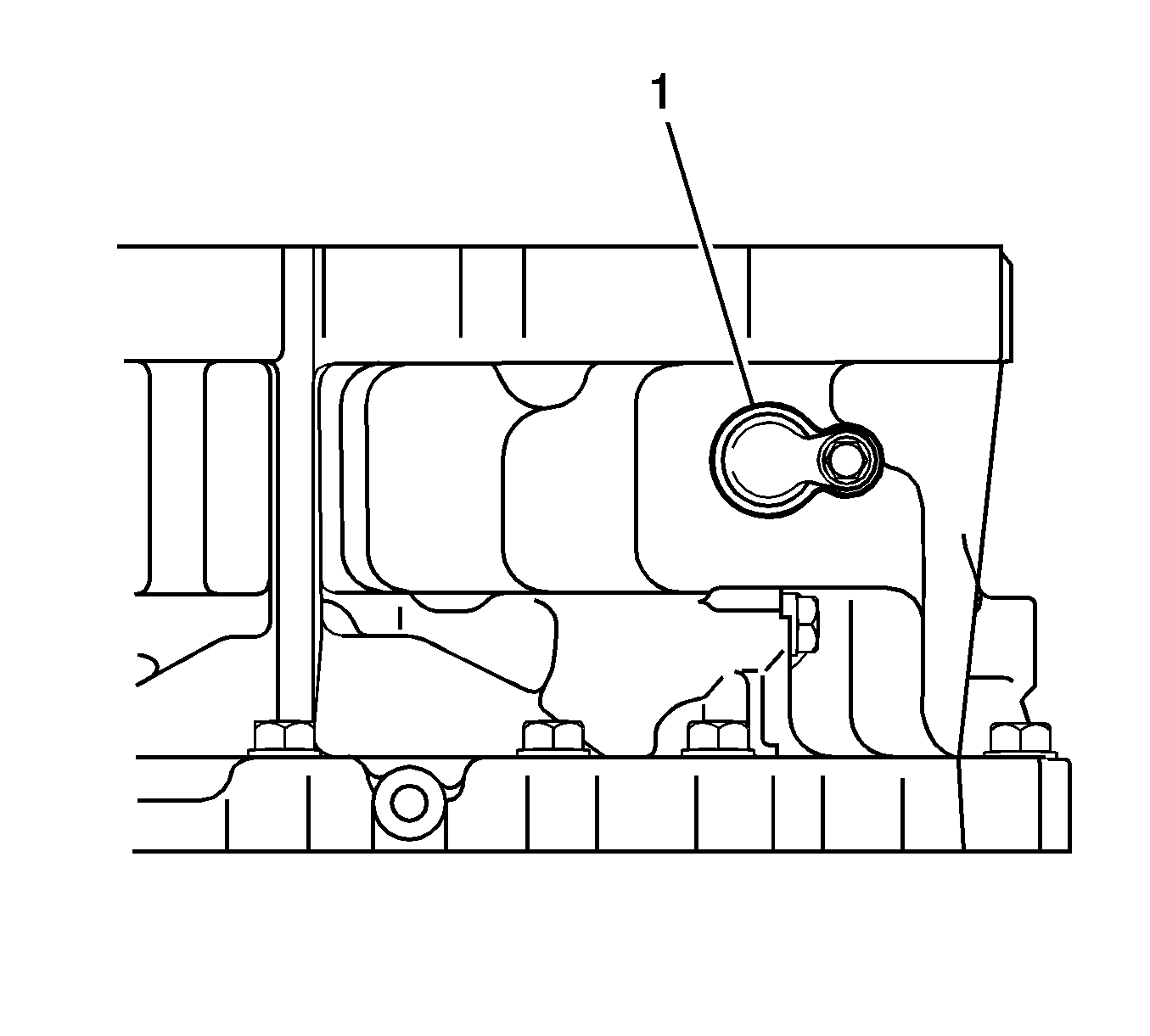
- Remove the bolt and the hole cover (1) from the transaxle case.
- Remove the O-ring from the hole cover.
- Remove the torque converter clutch from the automatic transaxle.
Installation Procedure
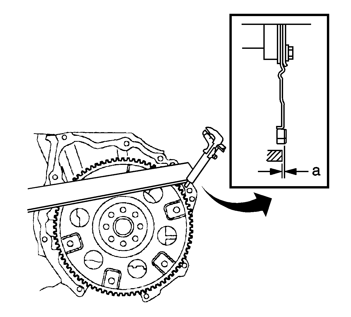
- Install the torque converter clutch to the automatic transaxle.
- Using a vernier caliper and straightedge, measure dimension A between the transaxle and the end surface of the drive plate.
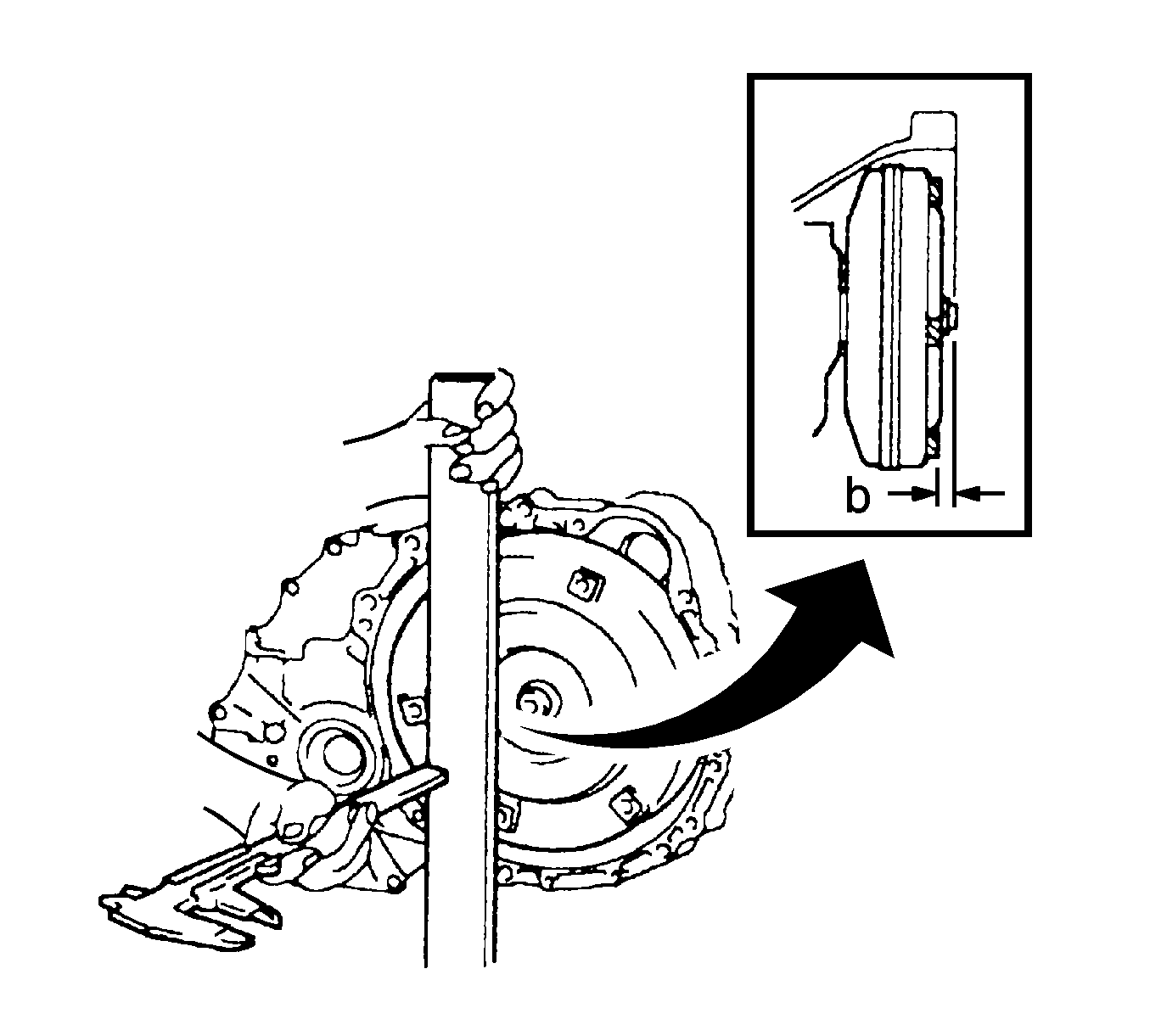
- Using a vernier caliper and straightedge, measure the dimension B shown in the illustration and check that B is greater than A.
Specification
Standard Dimension: - A+1.0 mm (0.039 in) or more
Caution: Refer to Fastener Caution in the Preface section.

- Install the hole cover (1) to the transaxle case with the bolt and tighten to
6 N·m (53 lb in).
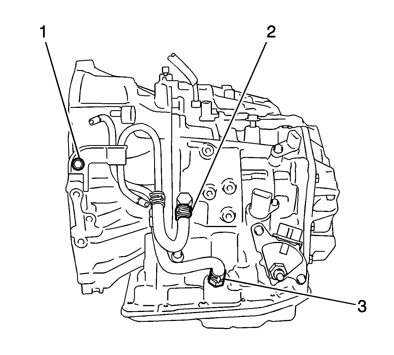
- Connect the oil cooler hoses to the unions with the hose clamps (2, 3).
- Install the oil cooler tube to the automatic transaxle with the bolt (1) and tighten to
12 N·m (106 lb in).
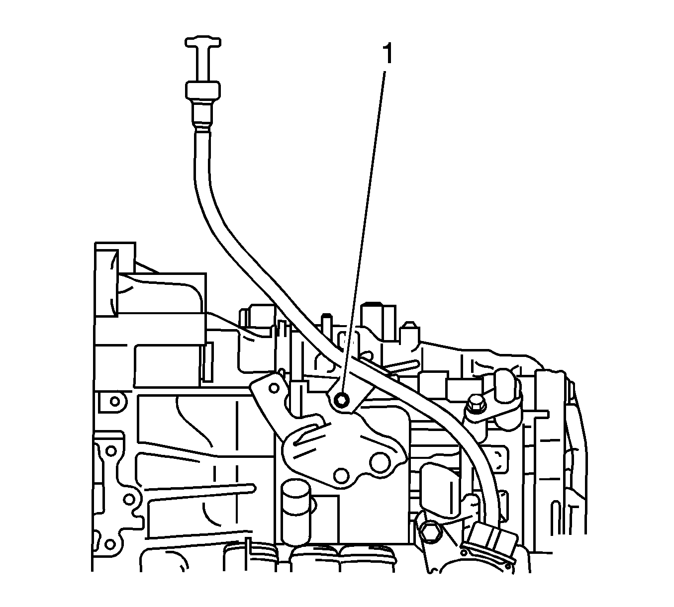
- Coat a new O-ring with ATF WS, and install it to the oil level indicator tube.
- Install the oil level indicator tube to the automatic transaxle with the bolt (1) and tighten to
6 N·m (53 lb in).
- Install the transmission oil level indicator.
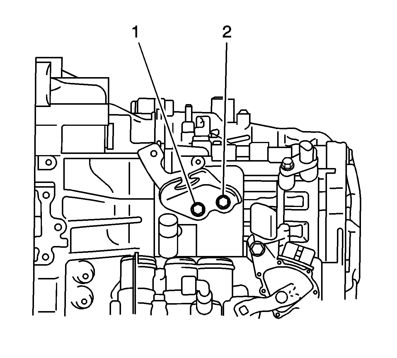
- Install the cable bracket with the bolts (1, 2) and tighten to
12 N·m (106 lb in).
- Install the transfer case assembly. Refer to
Transfer Case Assembly Replacement.
- Install the transfer stiffener plate right side.
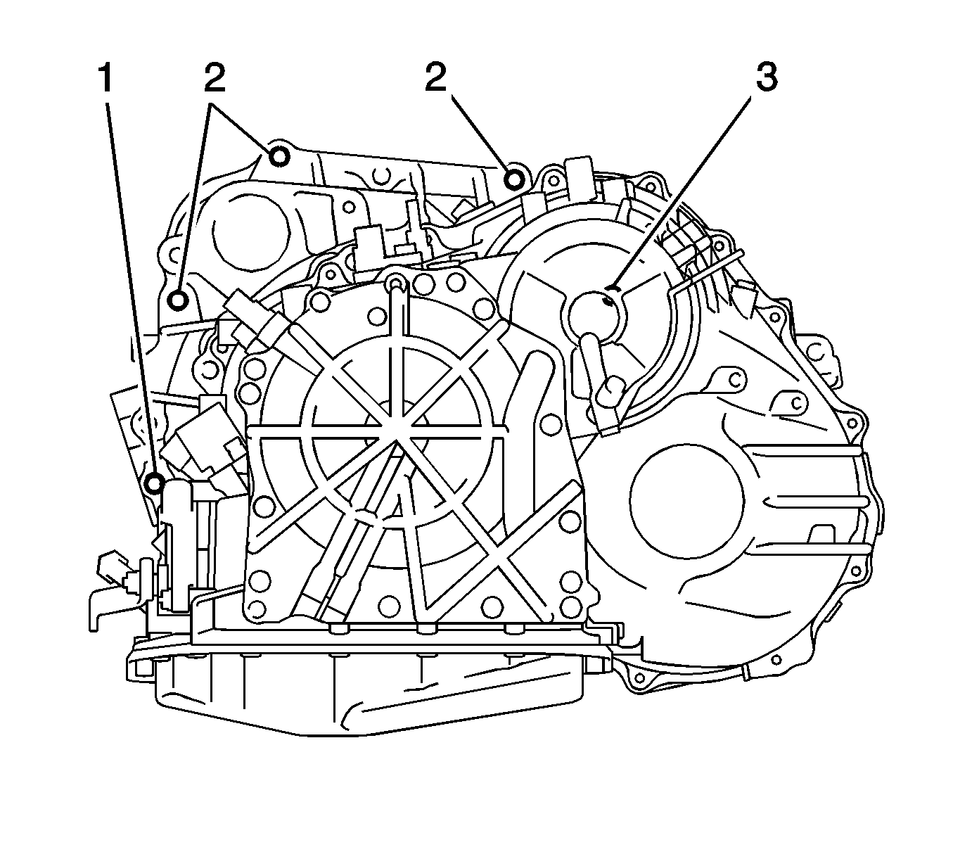
- Install the automatic transaxle with the upper side mounting bolts (1-3) to the engine and tighten.
| • | Bolt 1 -
46 N·m (34 lb ft) |
| • | Bolt 2 -
64 N·m (47 lb ft) |
| • | Bolt 3 -
46 N·m (34 lb ft) |
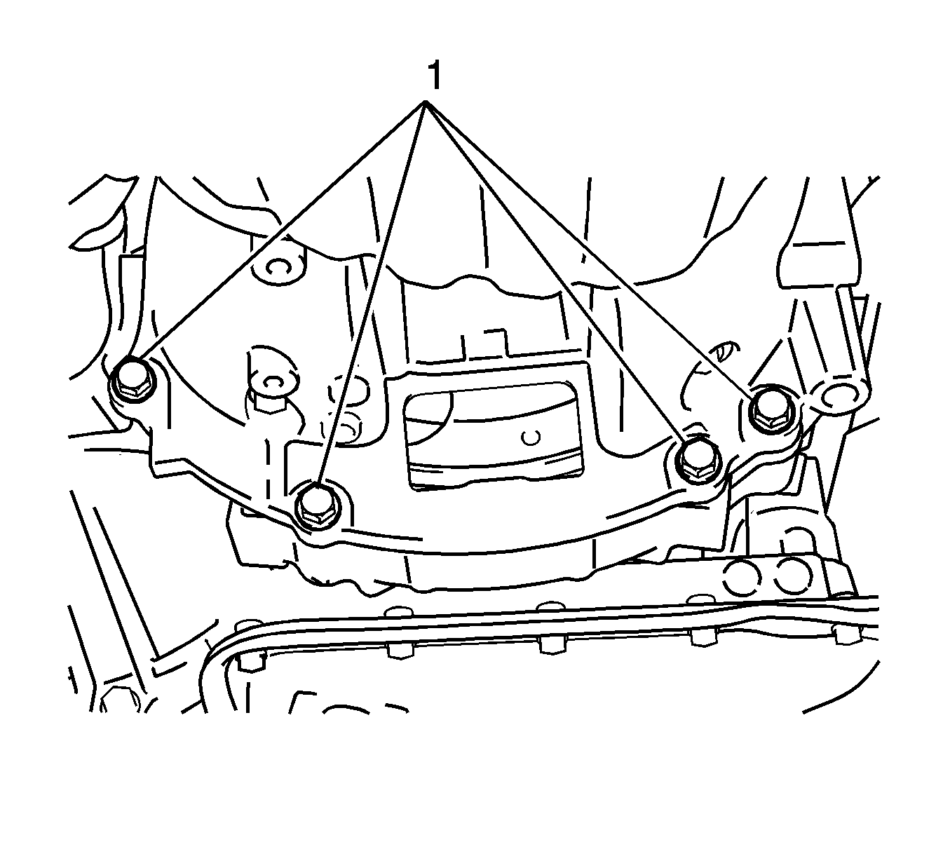
- Install the lower side mounting bolts (1) and tighten to
44 N·m (32 lb ft).
- Apply Three Bond 1324 or equivalent to the threads on the tip of the torque converter clutch mounting bolts.
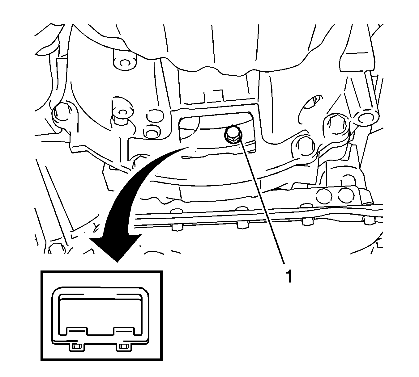
Note: Install the different colored bolt first, and then the remaining bolts.
- Install the torque converter clutch mounting bolts (1) and tighten to
41 N·m (30 lb ft).
- Install the flywheel housing under cover.

- Install the mounting bracket with the bolts (1-3) and tighten to
52 N·m (38 lb ft).
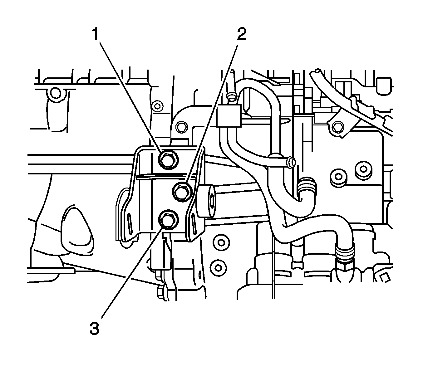
- Install the mounting bracket with the bolts (1-3) and tighten to
64 N·m
(47 lb ft).

- Install the mounting bracket with the bolts (1, 2) and tighten to
52 N·m (38 lb ft).
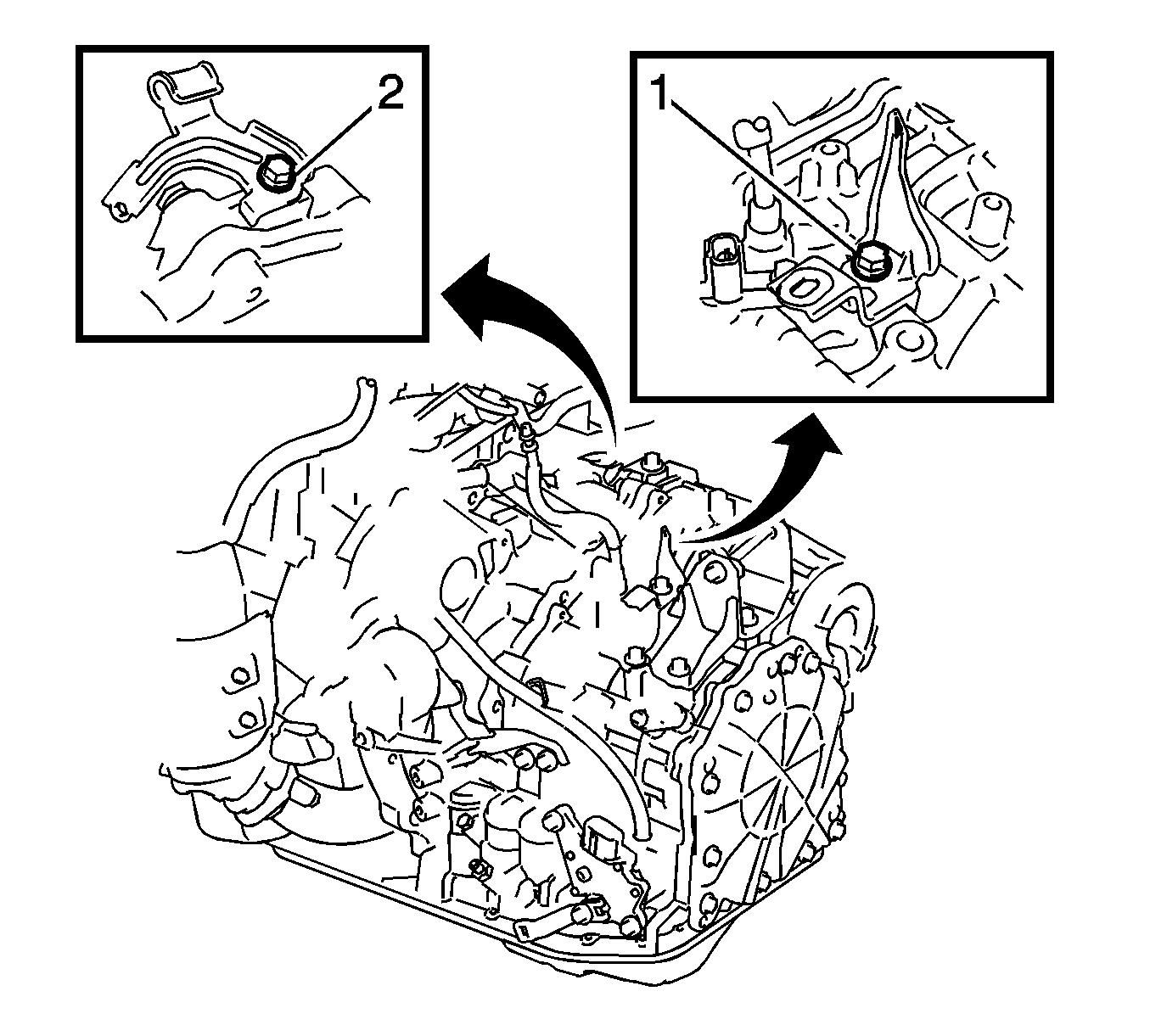
- Install the wire harness bracket and transmission control cable support with the bolts (1, 2).

- Connect the wire harness clamps.
- Connect the speed sensor connectors (2, 4).
- Connect the transmission wire connector.
- Connect the park/neutral position switch connector.
- Install the starter assembly. Refer to
Starter Replacement.
- Install the engine assembly with the transaxle. Refer to
Engine Replacement.


