For 1990-2009 cars only
Special Tools
EN-47935 (DW110-040) Engine and Transaxle Assembly Support Remover/Installer
Removal Procedure
- Discharge the air conditioning (A/C) system, if equipped.
- Drain the power steering oil, if equipped.
- Relieve the fuel system pressure. Refer to Fuel System Diagnosis.
- Disconnect the negative battery cable.
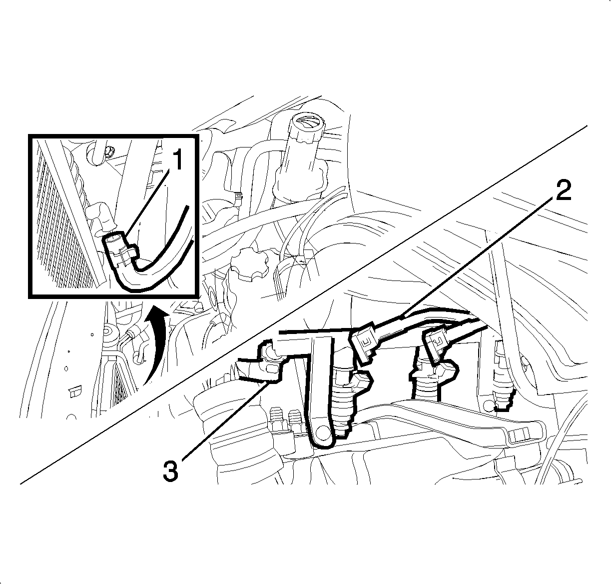
- Remove the air filter, resonator with snorkel assembly (1). Refer to Air Cleaner Element Replacement.
- Remove the engine ignition system ignition coil, if equipped.
- Disconnect the radiator lower hose (2) and drain the coolant. Refer to Cooling System Draining and Filling.
- Disconnect the fuel line inlet hose and the fuel injector wire connectors from the fuel rail (3).
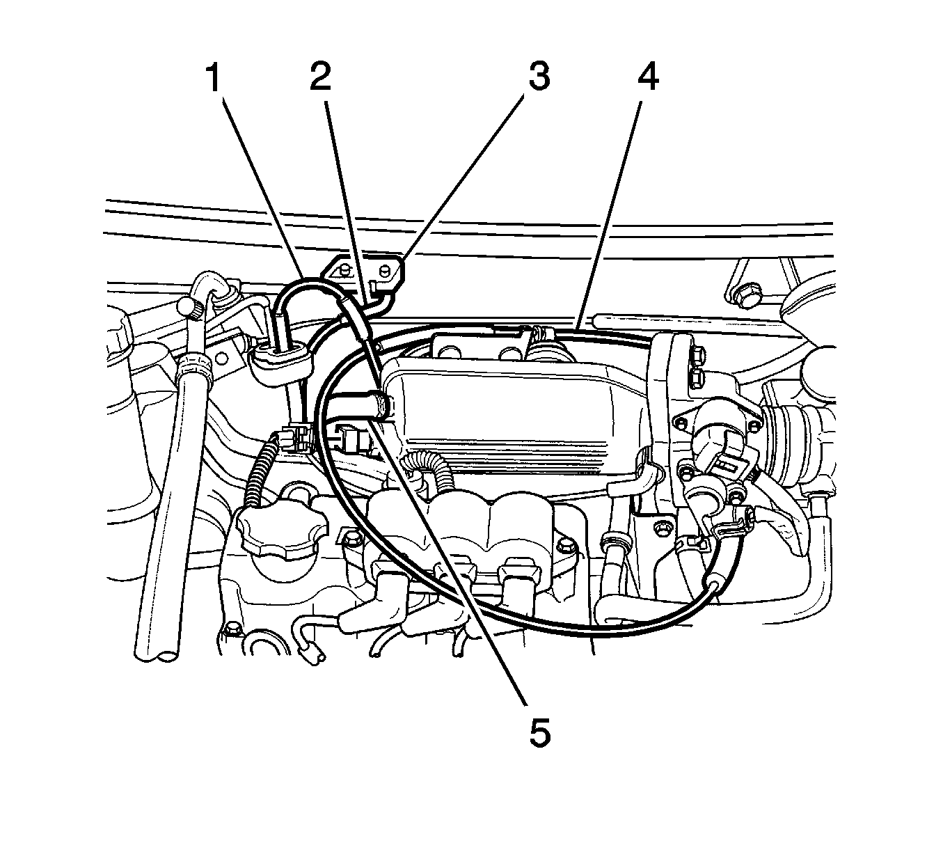
- Disconnect the throttle cable (4).
- Disconnect the manifold absolute pressure (MAP) sensor connector (3).
- Disconnect the canister solenoid connector (3).
- Disconnect the brake booster vacuum hose (5).
- Disconnect the MAP sensor vacuum hose (2).
- Disconnect the evaporative emission (EVAP) canister vacuum hose.
- Disconnect the intake air temperature (IAT) sensor connector.
- Remove the distributor. Refer to Distributor Replacement.
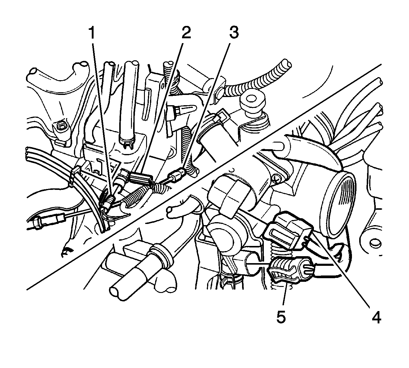
- Disconnect the engine coolant temperature (ECT) sensor connector (2).
- Disconnect the coolant temperature sensor connector (1).
- Disconnect the oxygen sensor connector (3).
- Disconnect the idle air control (IAC) valve connector (4).
- Disconnect the throttle position (TP) sensor connector (5).
- Disconnect the camshaft position (CMP) sensor connector and crankshaft position (CKP) sensor connector.
- Disconnect the heat core inlet hose.
- Disconnect the throttle body coolant outlet hose.
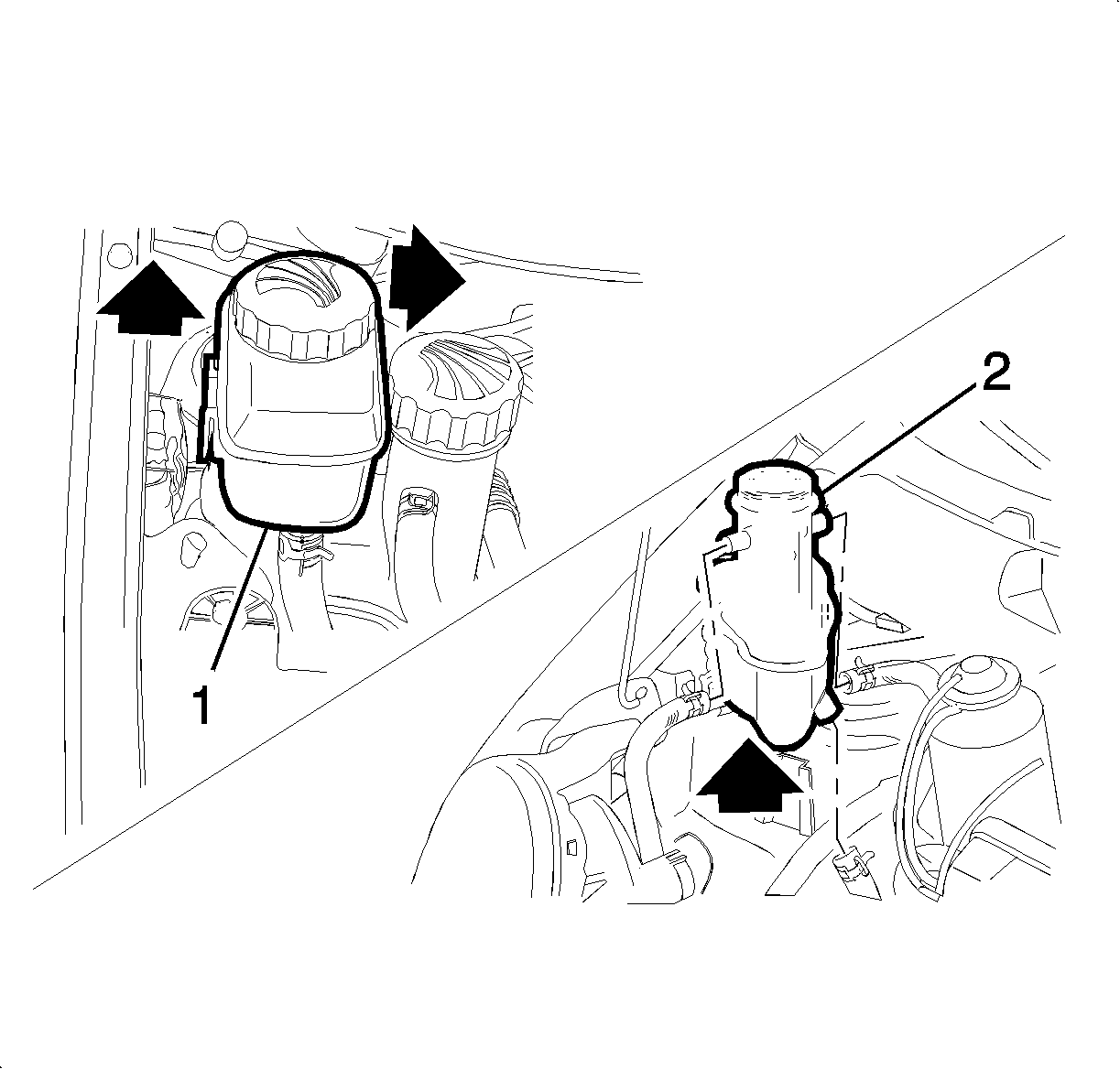
- Remove the power steering fluid reservoir (1), if equipped. Refer to Power Steering Fluid Reservoir Replacement.
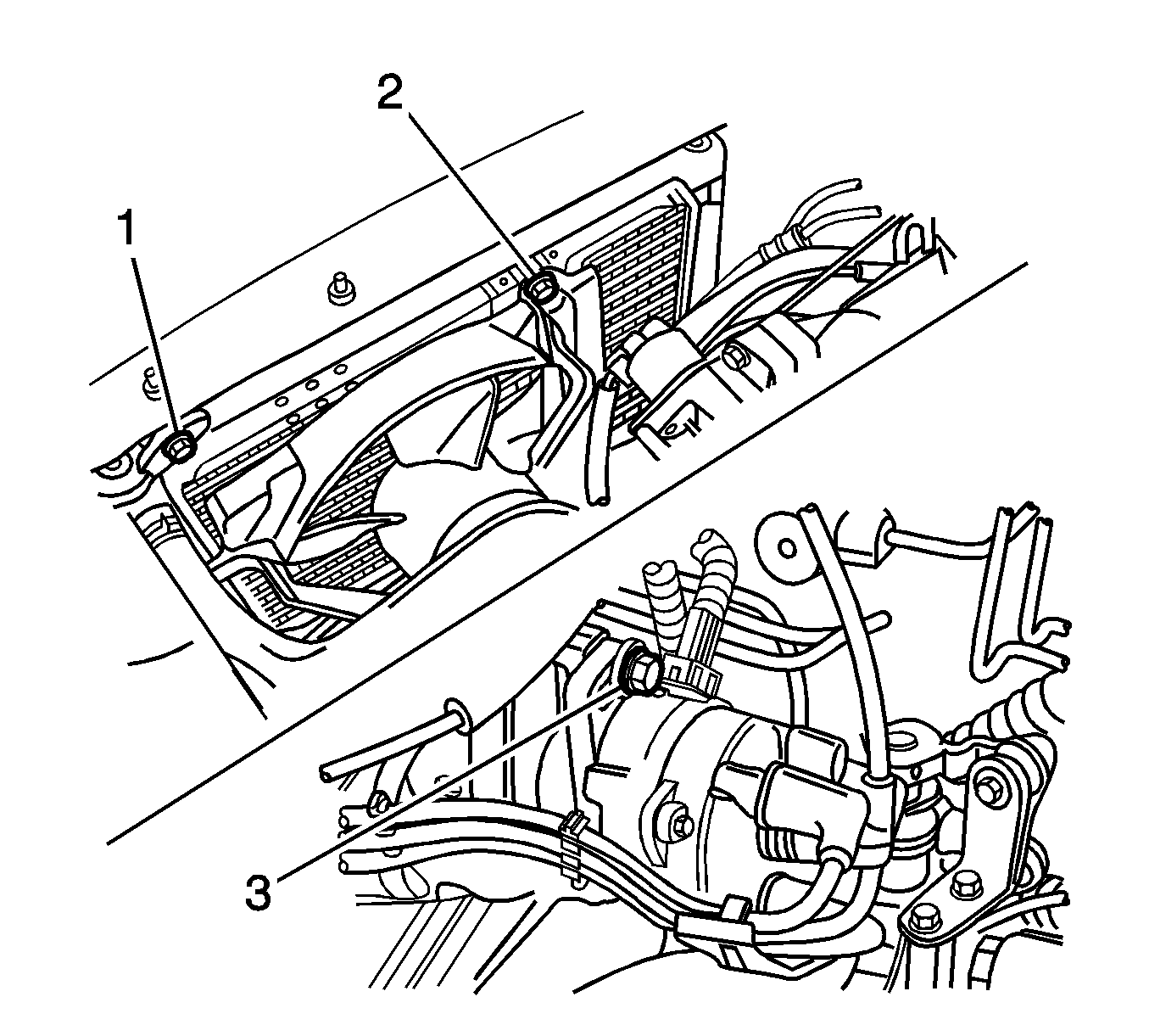
- Remove the coolant surge tank (2).
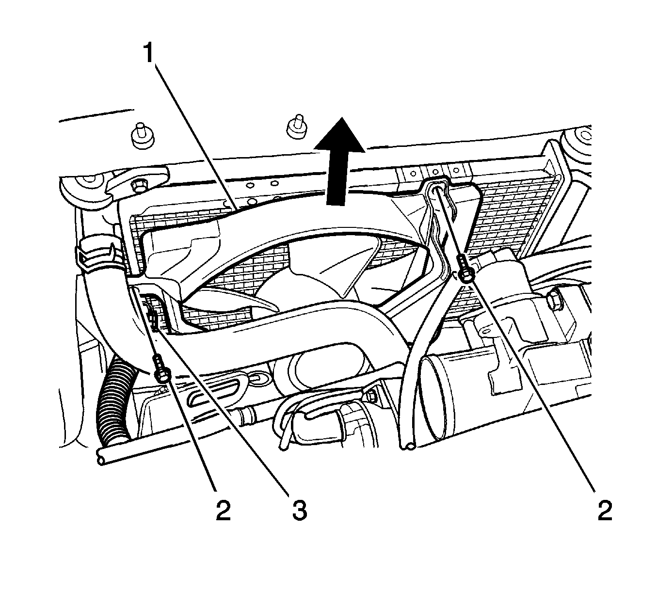
- Disconnect the coolant fan electrical connector (3).
- Loosen the coolant fan bolts (2).
- Take out the coolant fan assembly as shown in the picture (1).
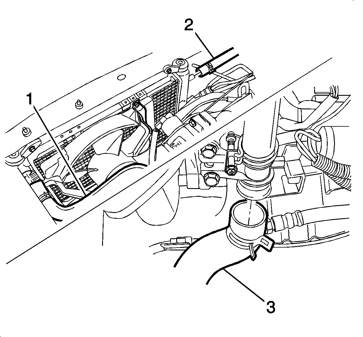
- Disconnect and remove the radiator upper hose (1).
- Disconnect and remove the radiator surge tank hose (2).
- Disconnect and remove the radiator lower hose (3).
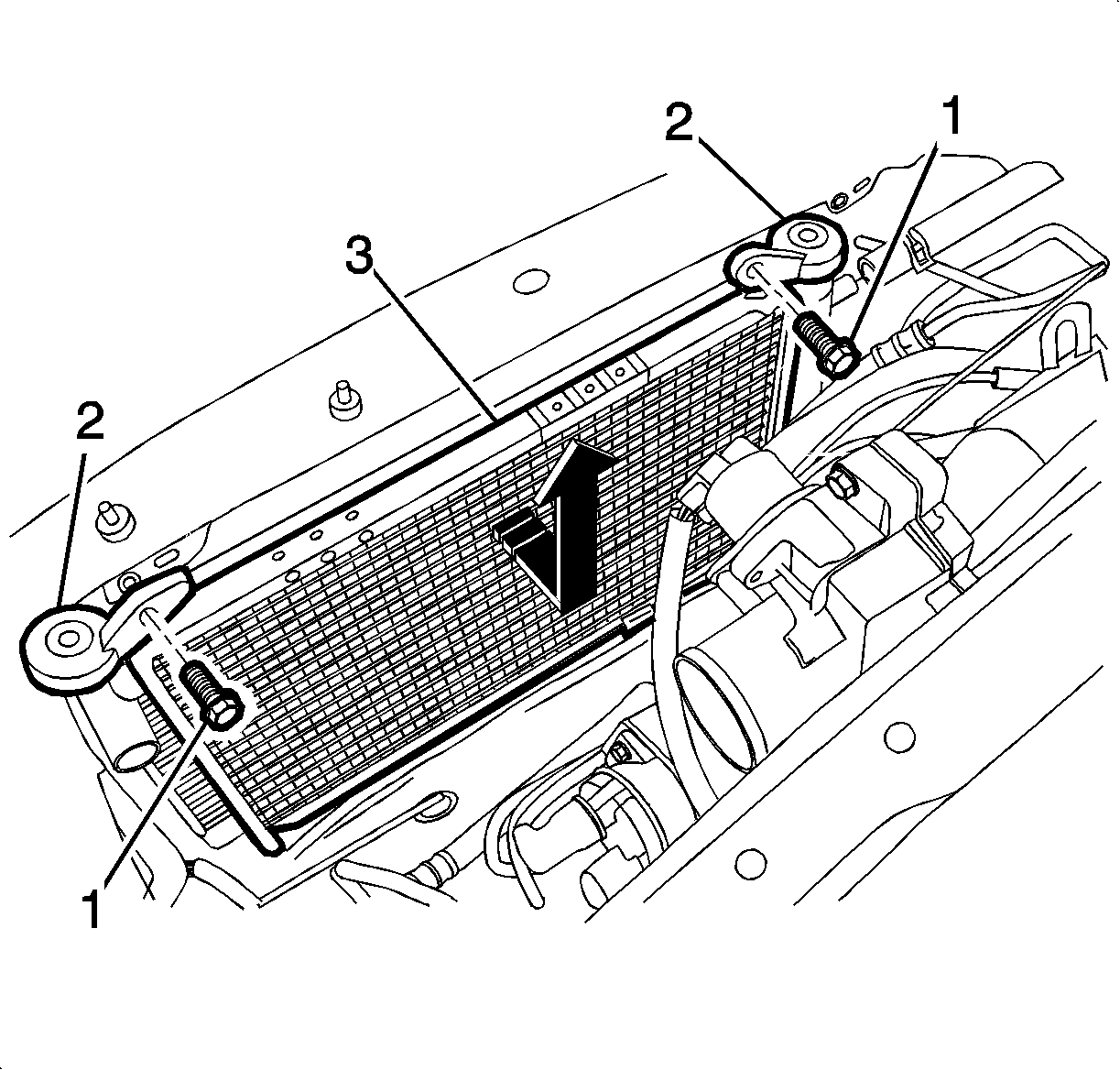
- Loosen the radiator bolts (2).
- Remove the radiator mounting brackets (1).
- Take out the radiator as shown in the picture (3).
- If equipped with the air conditioning (A/C) system and the power steering, disconnect the connectors, the pipes, and the hoses.
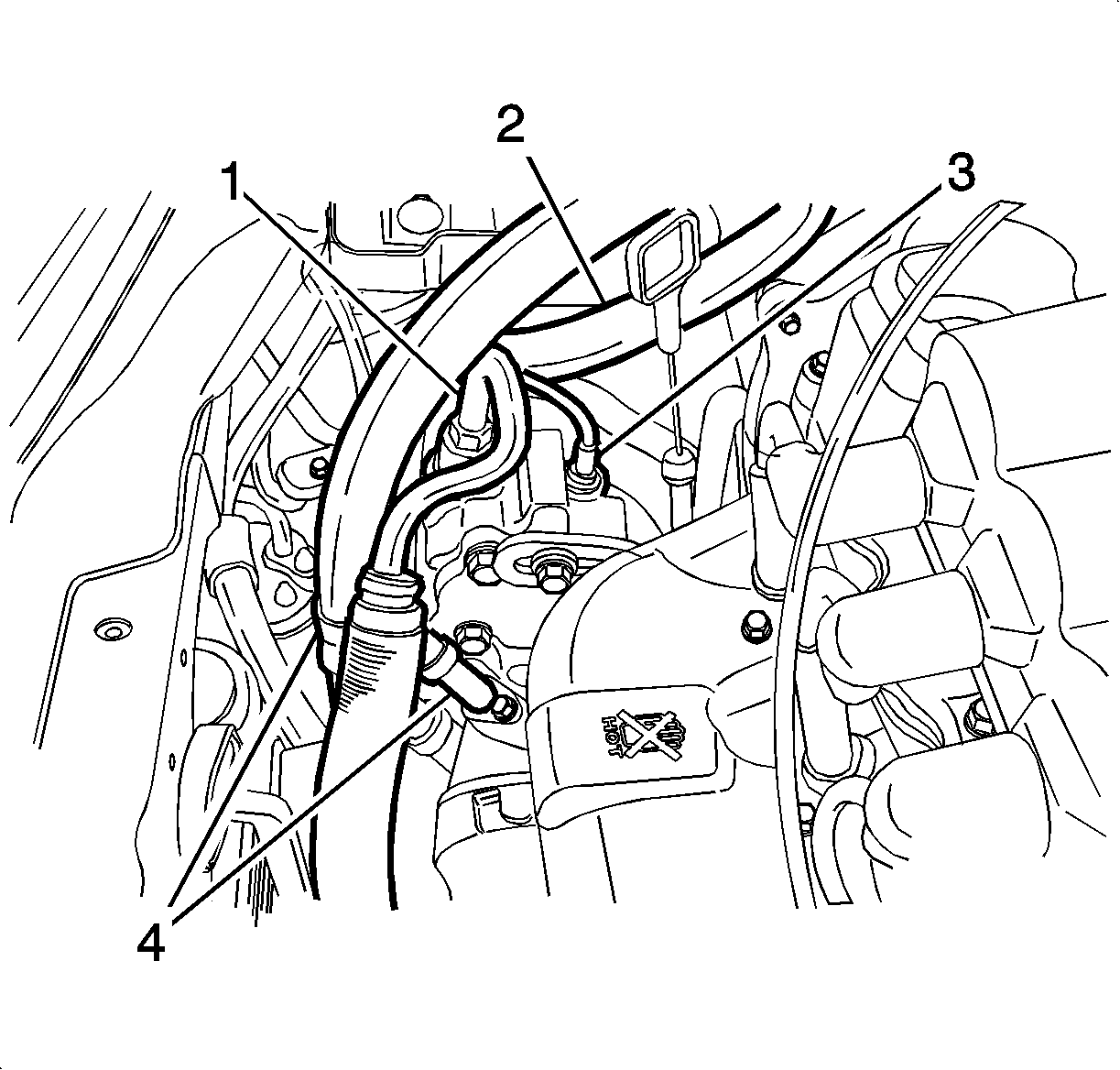
- Disconnect the power steering pressure sensor connector (3).
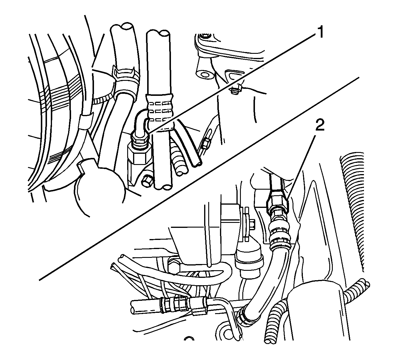
- Disconnect the hose from the power steering pump (2).
- Disconnect the pipe from the power steering pump (1).
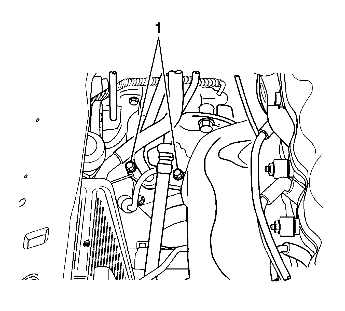
- Disconnect the air conditioning low and high pressure pipes (4).
- Disconnect the power steering hose.
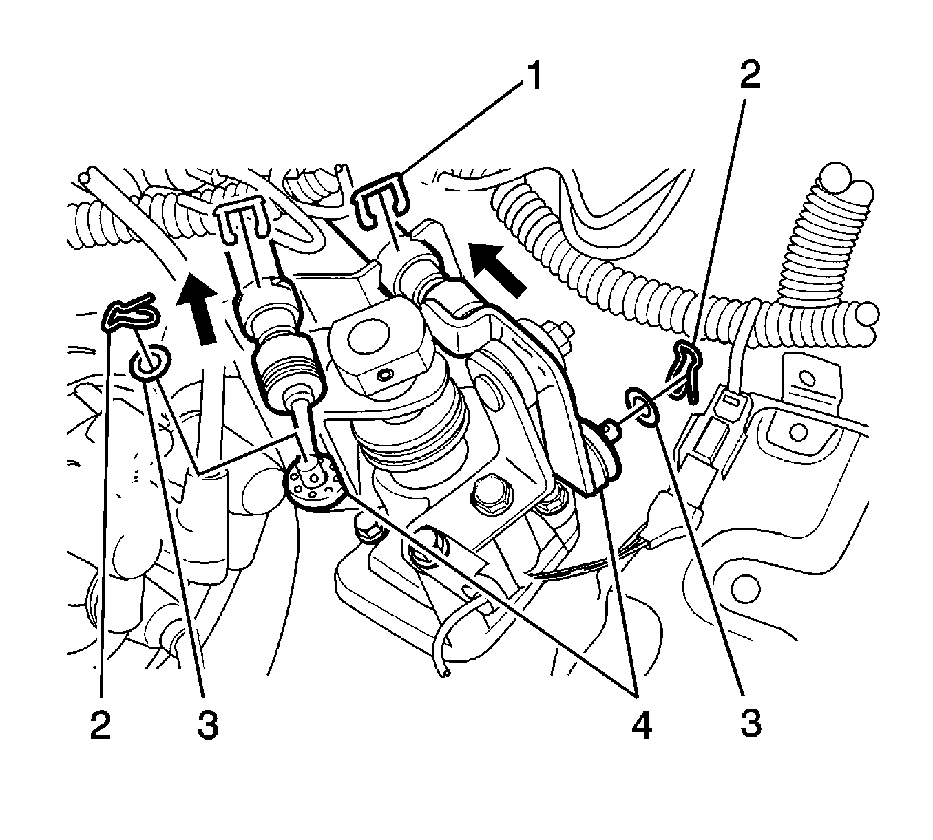
- Remove the select and shift cable pin (2).
- Remove the select and shift washer (3).
- Disconnect the select and shift cable (4).
- Remove the E-ring (1).
- Remove the engine electrical wire bending strap.
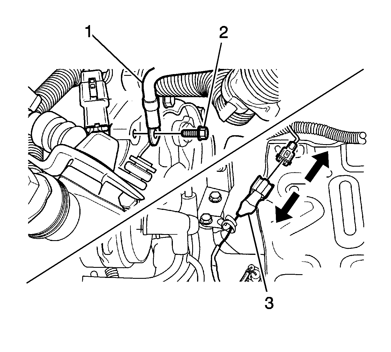
- Loosen the transaxle case ground connection line bolt (2).
- Disconnect the transaxle case ground connection line (1).
- Disconnect the backup lamp switch electrical connector (3).
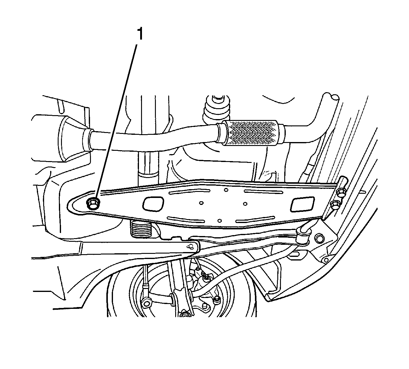
- Remove the transaxle under cover bolts (2).
- Remove the transaxle under cover (1).
- Remove the transaxle oil drain plug and drain oil.
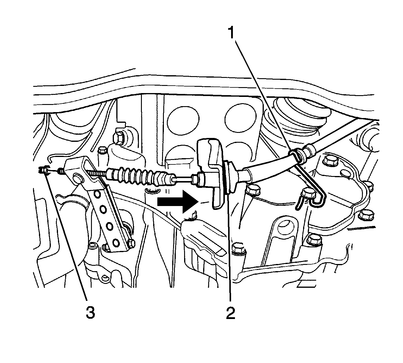
- Loosen the clutch cable adjusting nut (3).
- Disconnect the clutch cable from the wire clip (1).
- Disconnect the clutch cable from the transaxle mount hole (2).
- Loosen the speedometer cable nut (1).
- Disconnect the speedometer cable (2).
- If equipped, disconnect the vehicle speed sensor electrical connector.
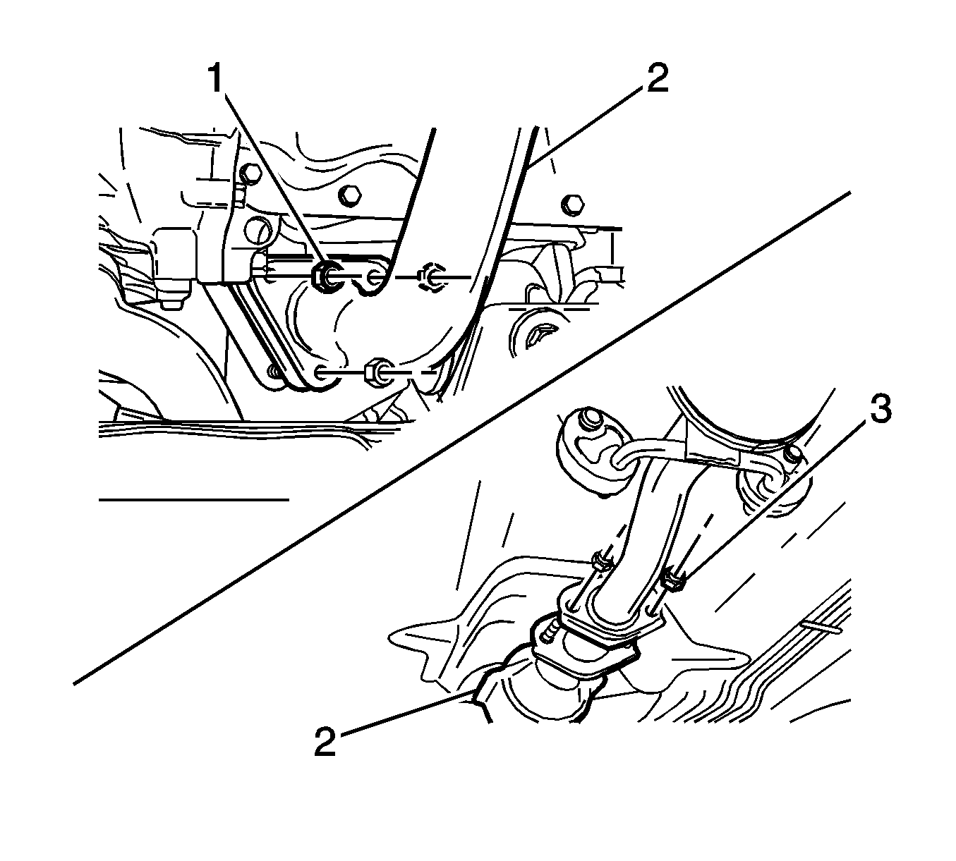
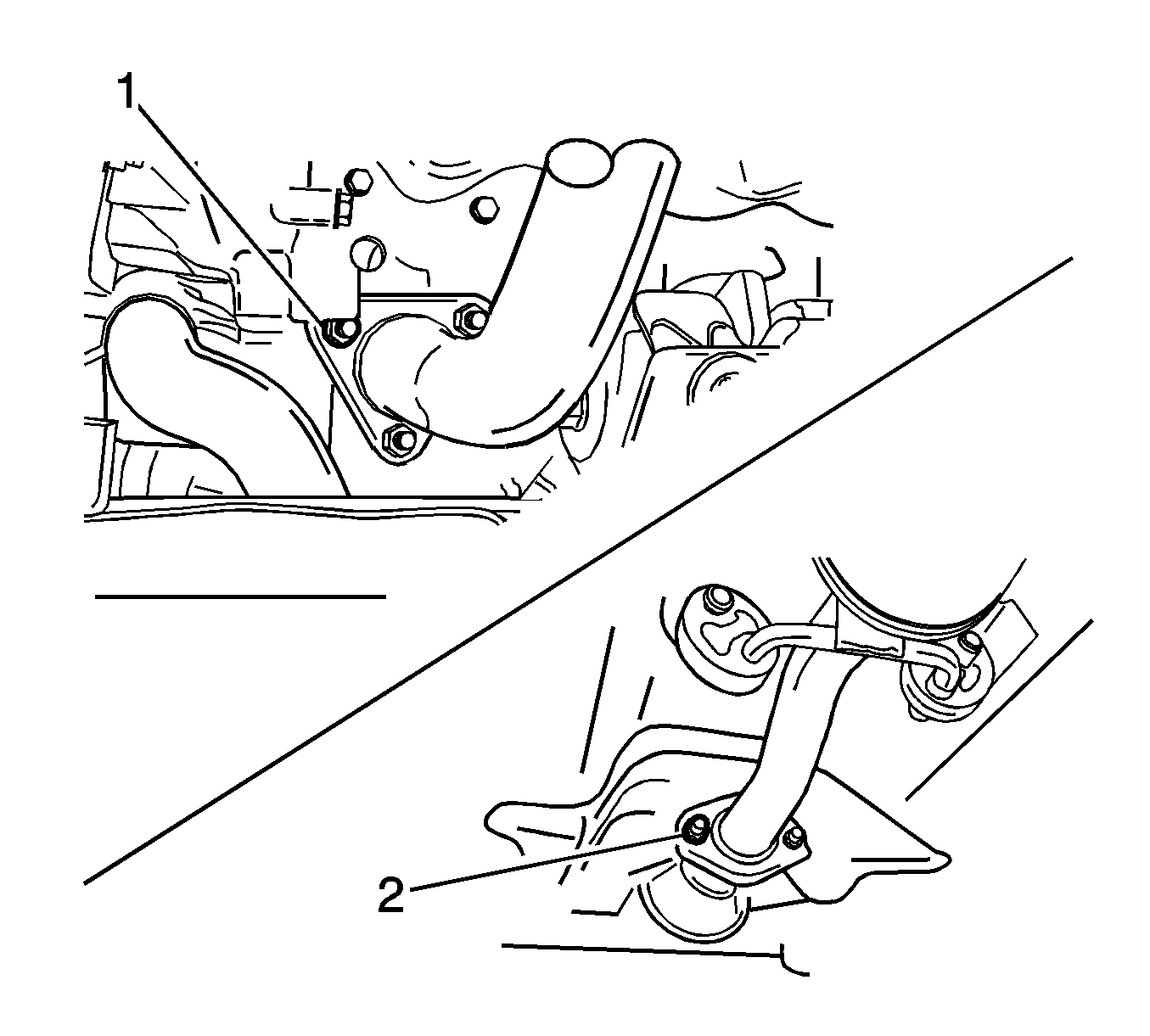
- Loosen the front exhaust pipe nuts (1).
- Remove the gasket and disconnect the pipe (4).
- Loosen the nuts (3).
- Remove the front exhaust pipe (2).
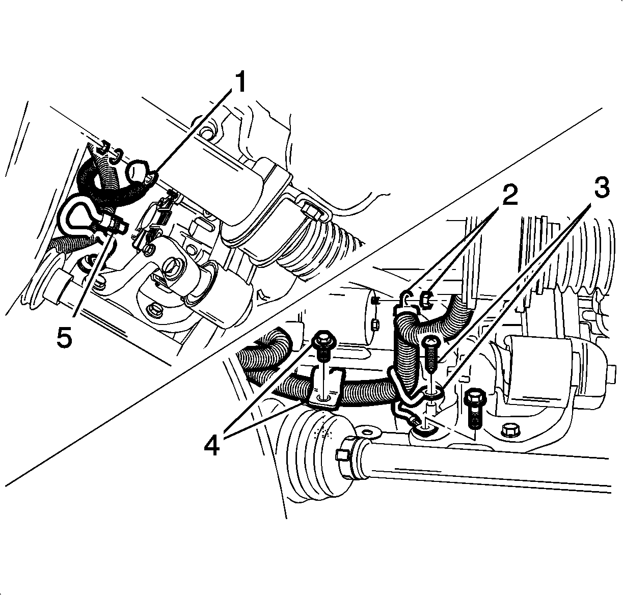
- Disconnect the oil pressure switch electrical connector (3).
- Disconnect the generator B+ terminal (1).
- Disconnect the generator electrical connector (5).
- Disconnect the starter electrical connector (2).
- Disconnect the electrical wire strap (4).
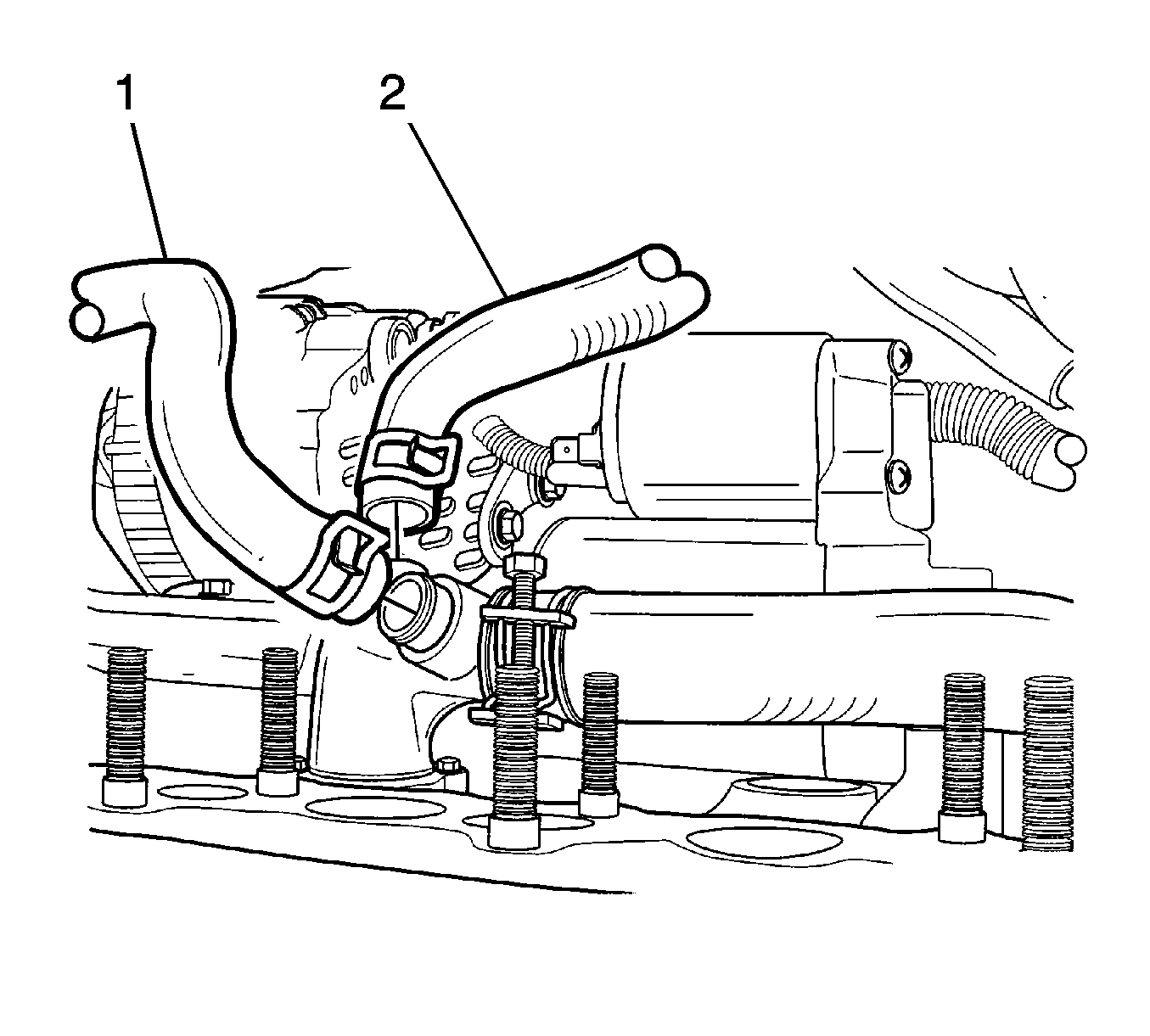
- Disconnect the surge tank coolant return hose (1) and the heater outlet hose (2).
- Remove both of the front wheels. Refer to Tire and Wheel Removal and Installation.
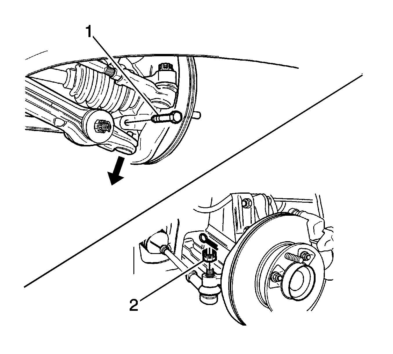
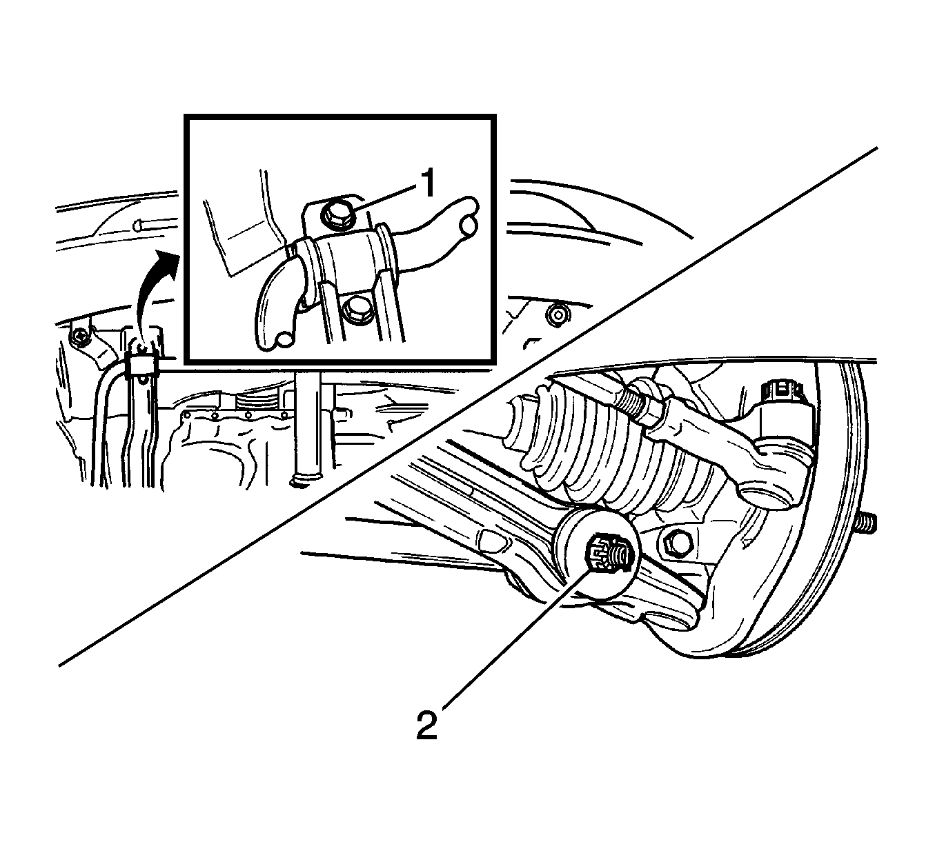
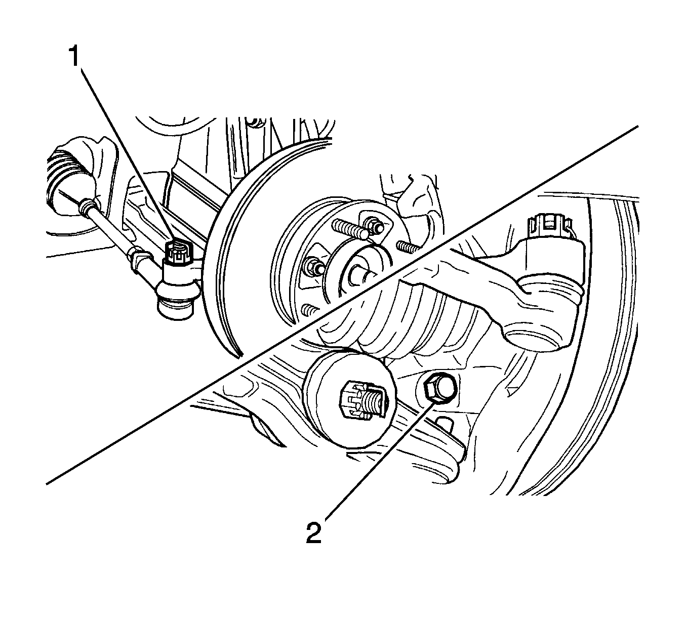
- Remove the control arm (1) and the tie rod end (2). Refer to Control Arm Replacement.
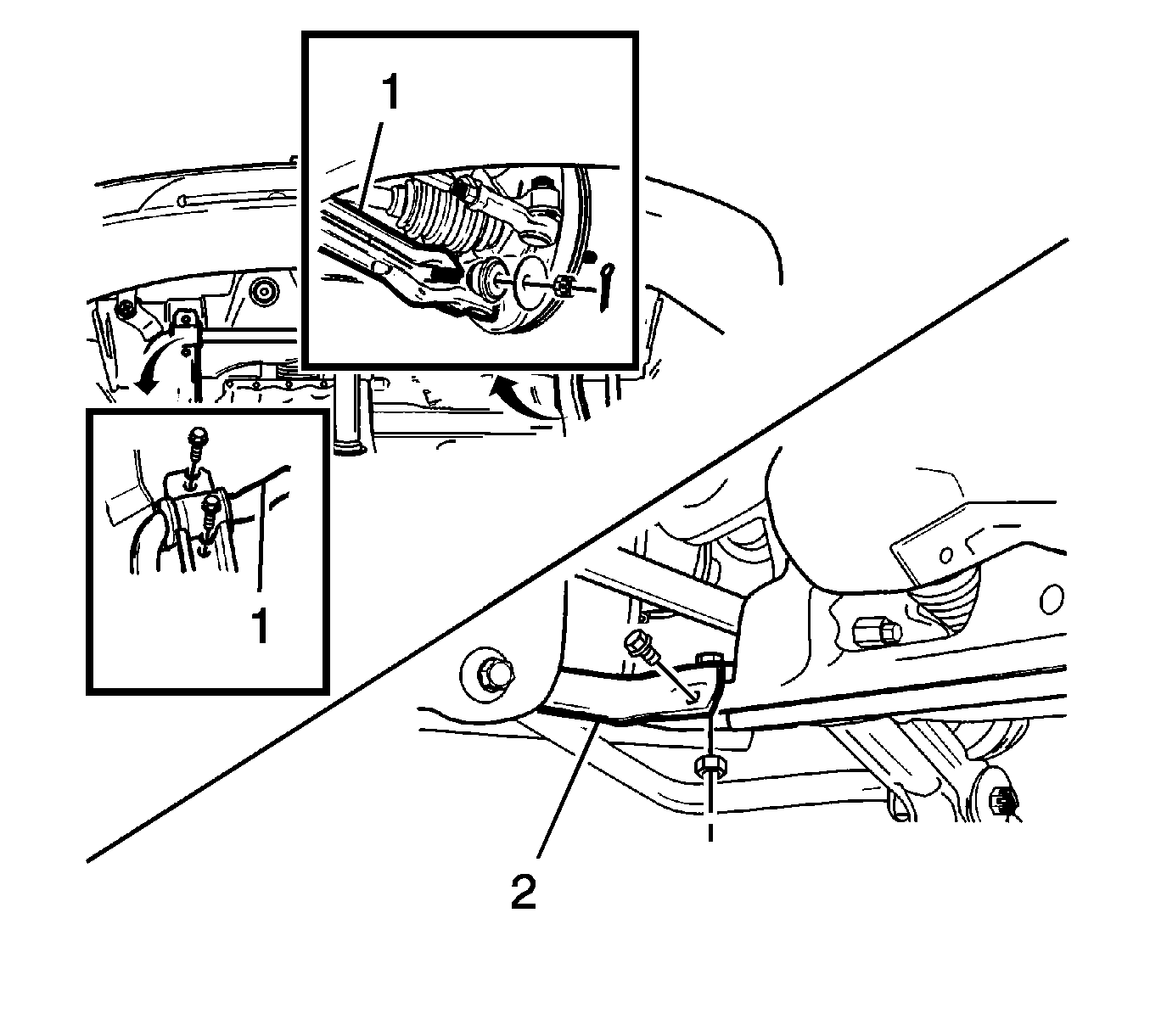
- Remove the left and right front longitudinal member (2) and stabilizer bar (1). Refer to Stabilizer Shaft Replacement.
- Loosen the caulking nut. Refer to Wheel Hub, Bearing, Knuckle, and Seal Replacement.
- Remove the wheel side drive axle (1).
- Insert a driver between the transaxle case and the drive axle joint case (2).
- Remove the differential side drive axle, as shown (3).
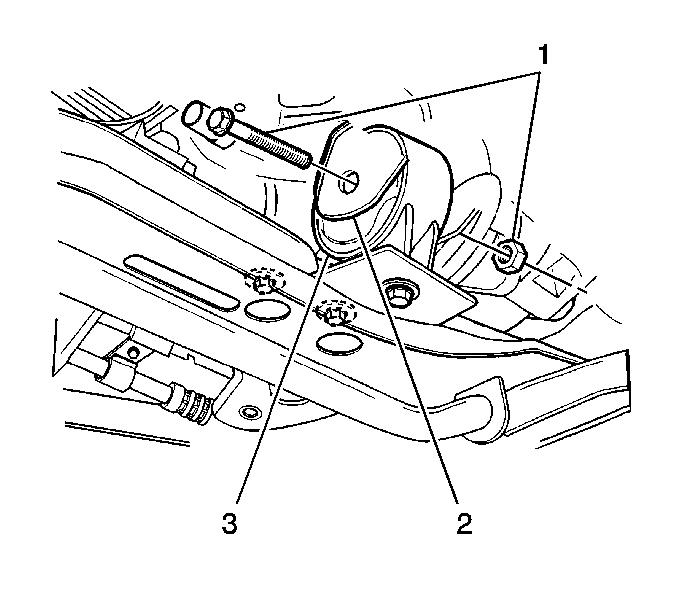
- Remove the damping bush assembly bolt and nut (1).
- Remove the engine mount front bracket (2) and the damping bush assembly (3).
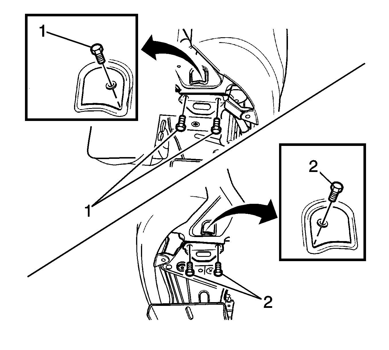
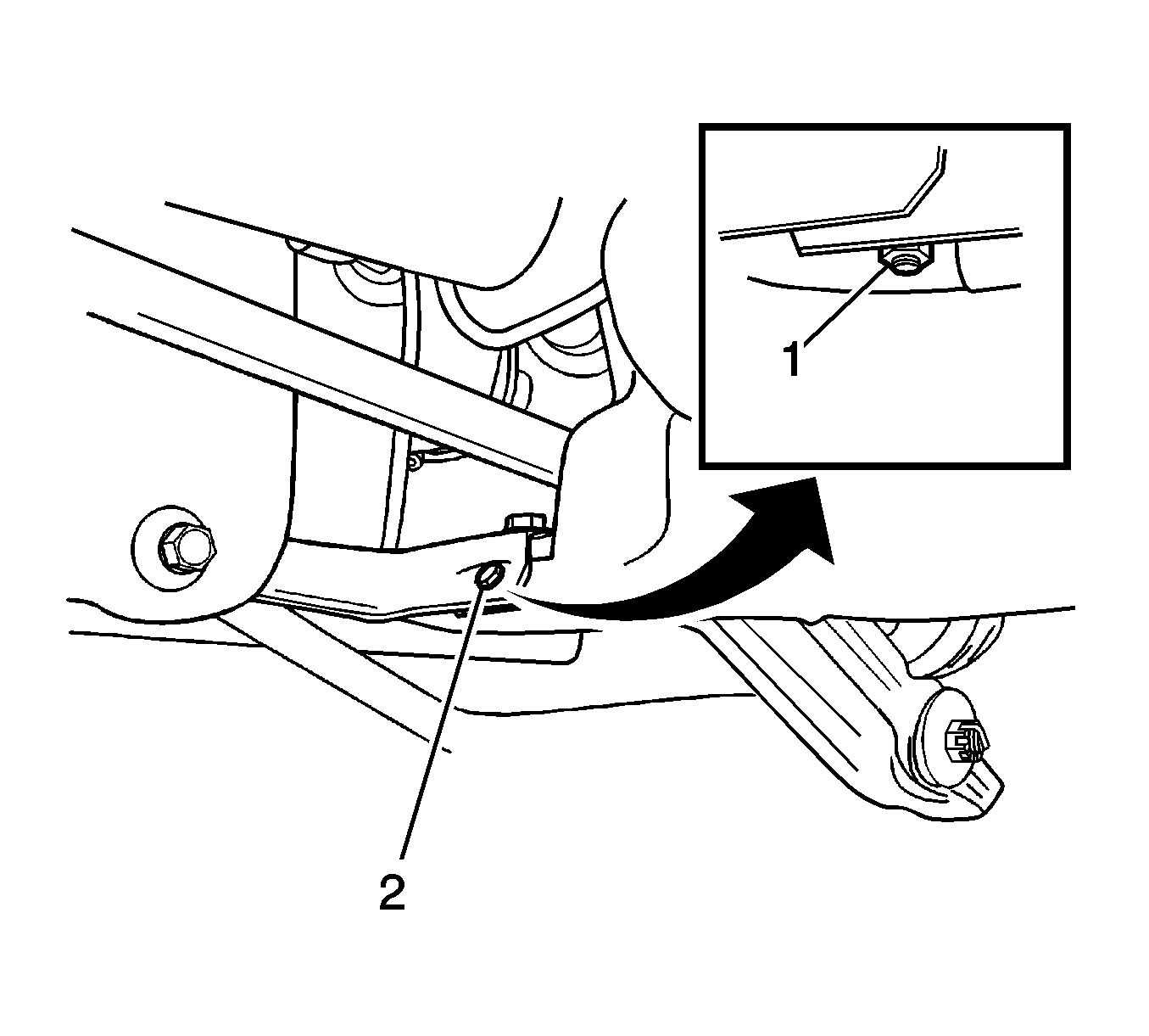
- Remove the right (1) and left (2) crossmember. Refer to Front Suspension Crossmember Replacement.
- Loosen the engine mount intermediate bracket nut (1).
- Support the oil pan with the EN-47935 .
- Loosen the bolt from the body bracket (2).
- Remove the engine mount reaction rod (3).
- Loosen the transaxle mount bolts (1) and remove the mount.
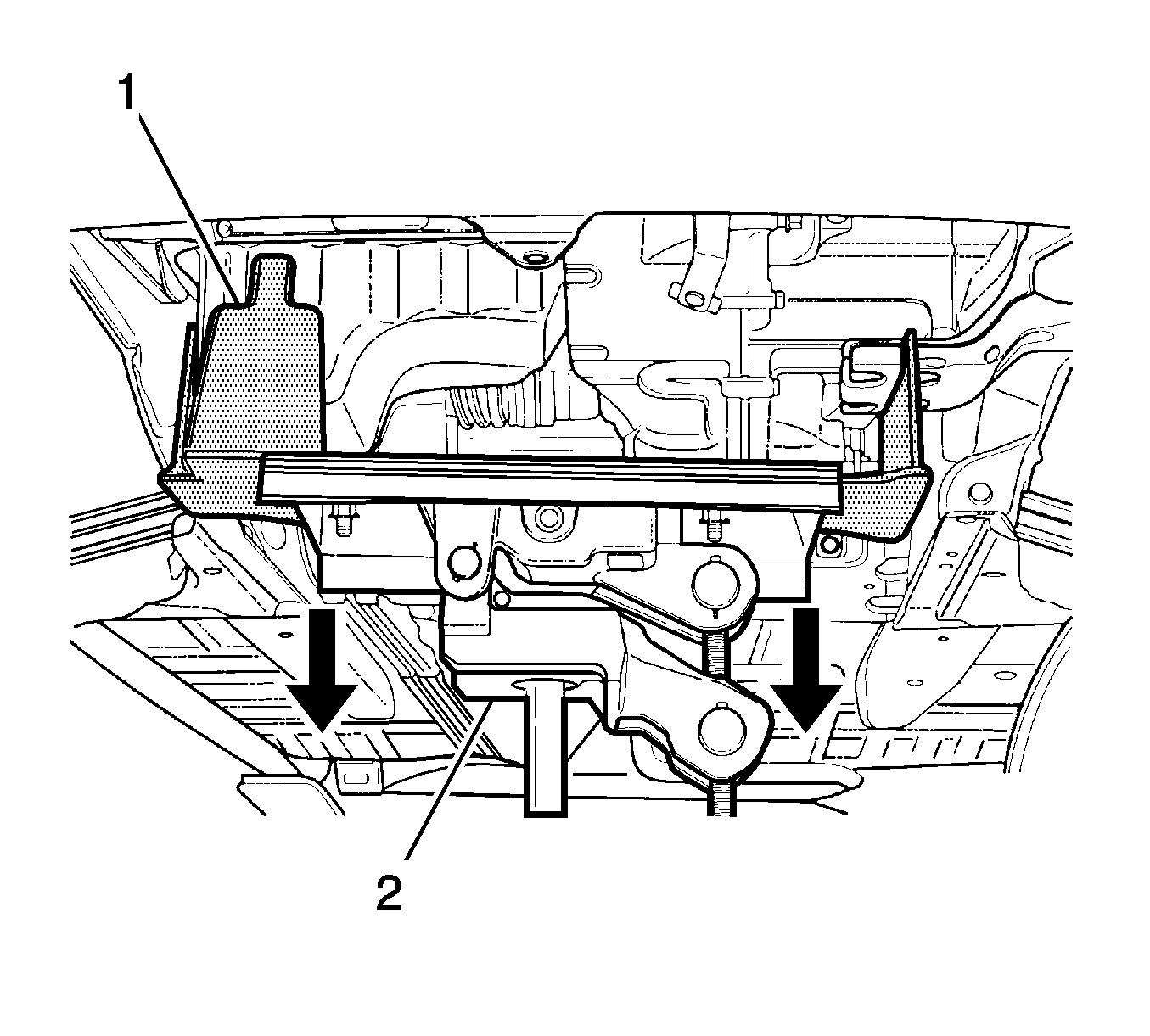
- Remove the engine and transaxle assembly (1) by slowly lowering the special tool (2).
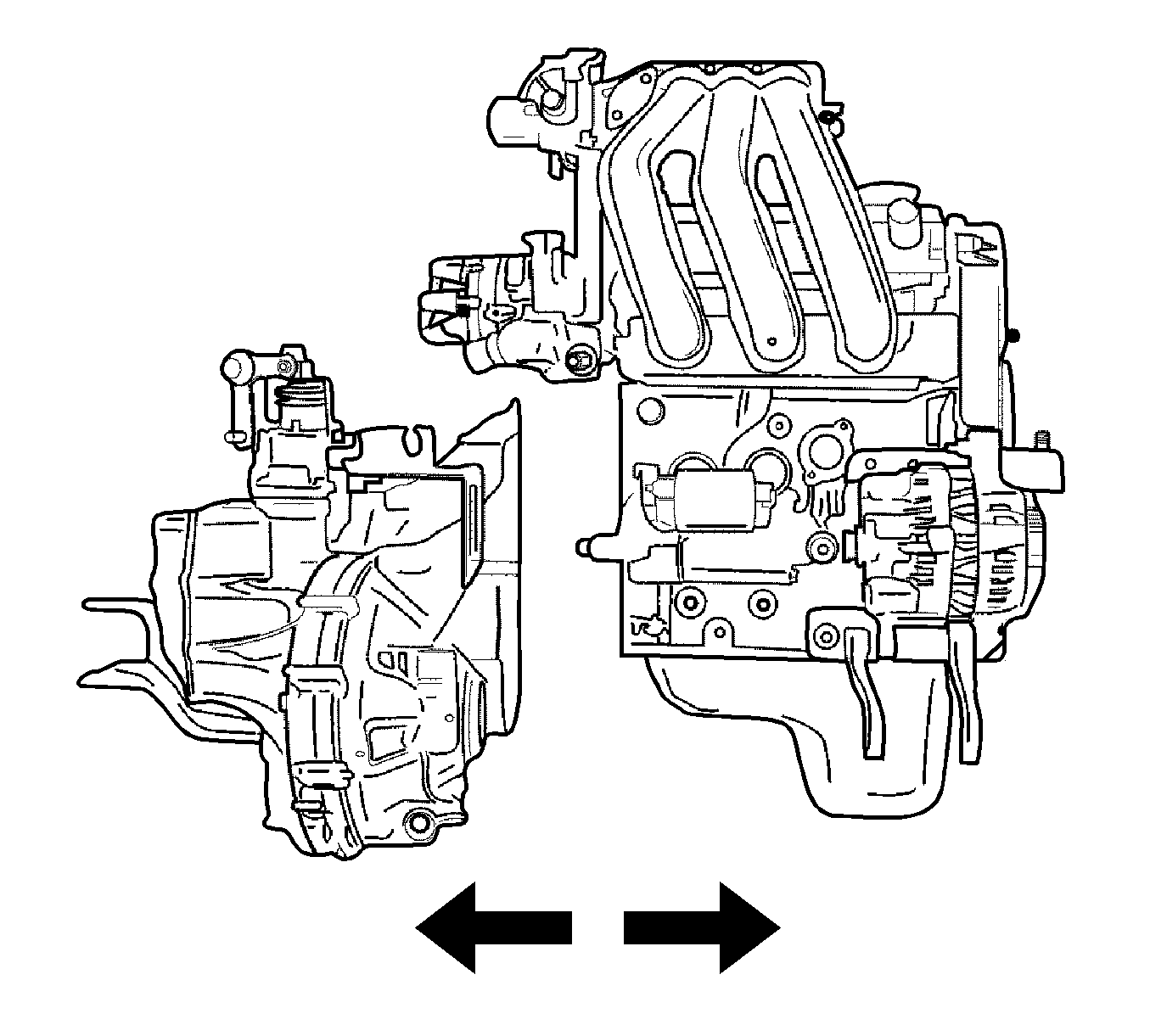
- Remove the transaxle from the engine/transaxle assembly. Refer to Transmission Replacement for the Y4M transmission.
- Remove some parts to be equipped with the engine assembly. Refer to Cylinder Head Disassemble.
Warning: Refer to Breathing R-134a Warning in the Preface section.
Warning: Refer to Battery Disconnect Warning in the Preface section.


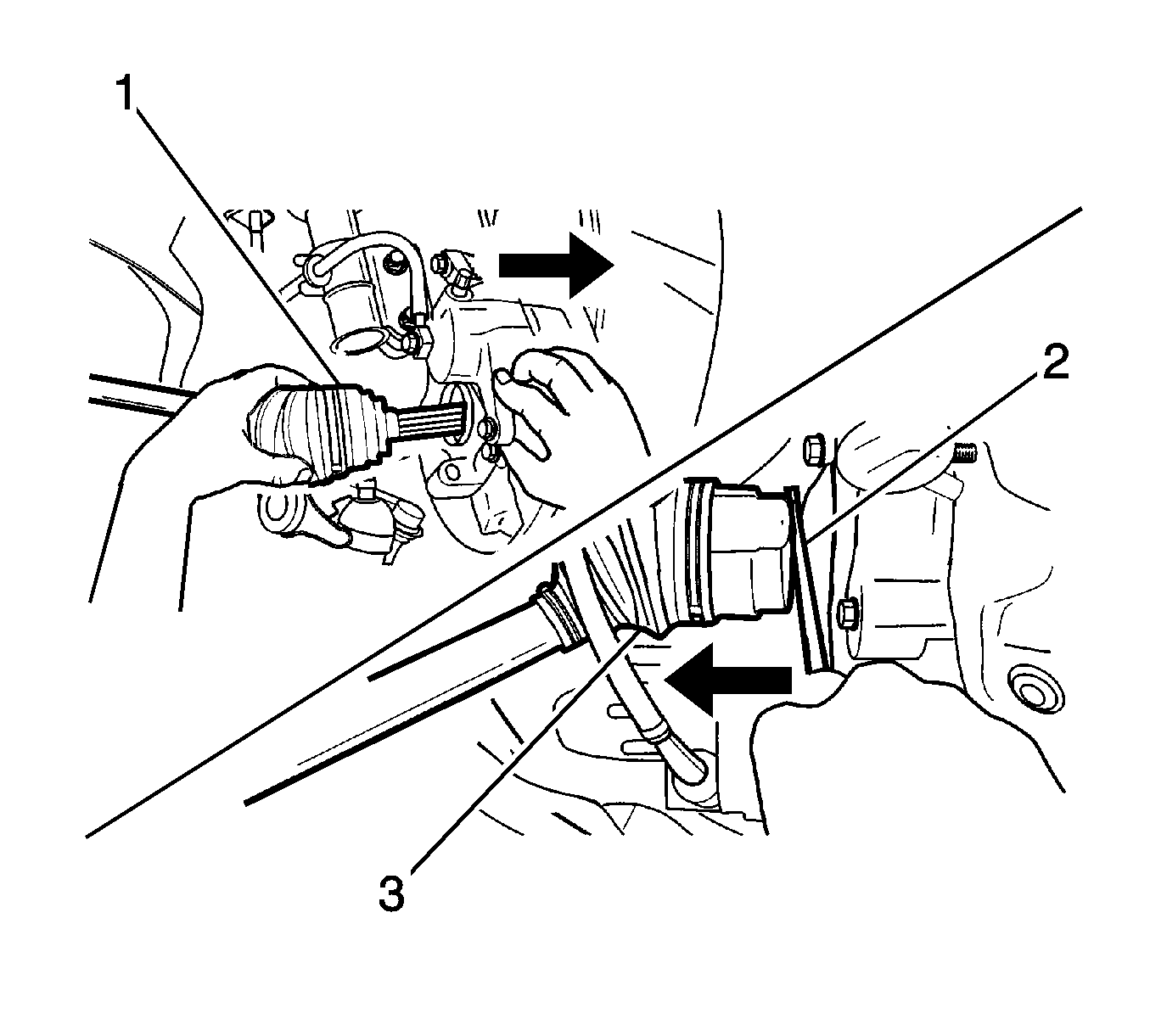
Caution: When removing the drive axle, use extreme care not to nick or cut the drive axle oil seal.
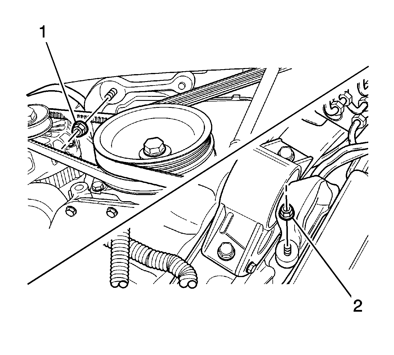
Note: Before loosening the engine mount intermediate bracket nut, oil pan should be supported by the EN-47935 .
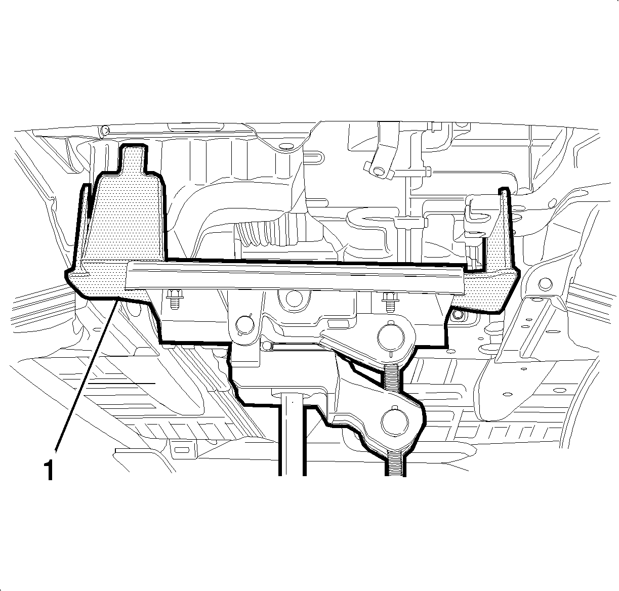
Loosen the bolt and nut from the engine mount lower bracket (1).
Installation Procedure
- Install the transaxle to the engine assembly. Refer to Transmission Replacement for the Y4M transmission.
- Place the engine and transaxle assembly on the EN-47935 making sure that the assembly is properly supported.
- Install the engine and transaxle assembly in to the vehicle by slowly raising the EN-47935 .
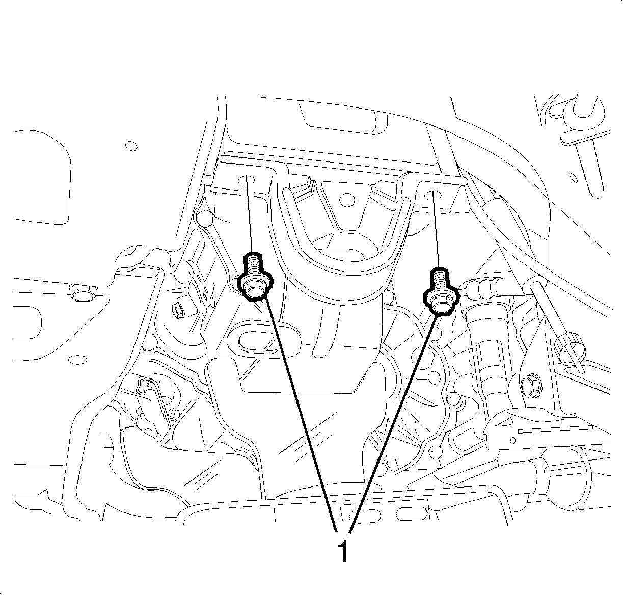
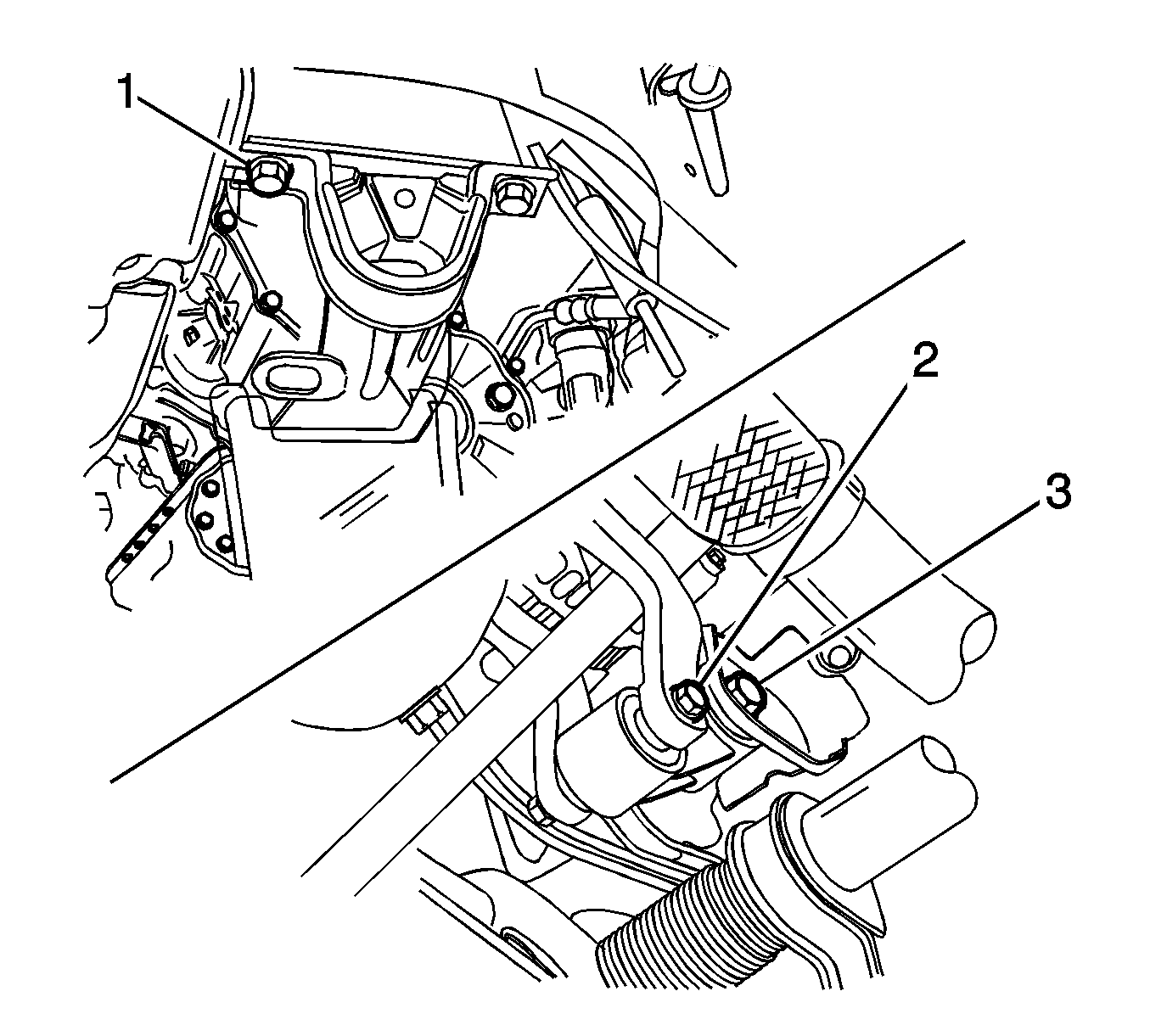
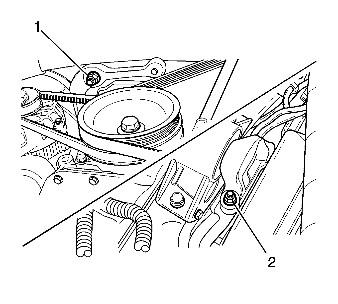
- Install the transaxle mount and bolts (1) and tighten to 45-55 N·m (33-41 lb ft).
- Install the engine mount reaction rod (2, 3) and tighten to 68-83 N·m (50-61 lb ft).
- Install the engine mount intermediate bracket and nuts (1, 2) and tighten to 60-70 N·m (44-52 lb ft).
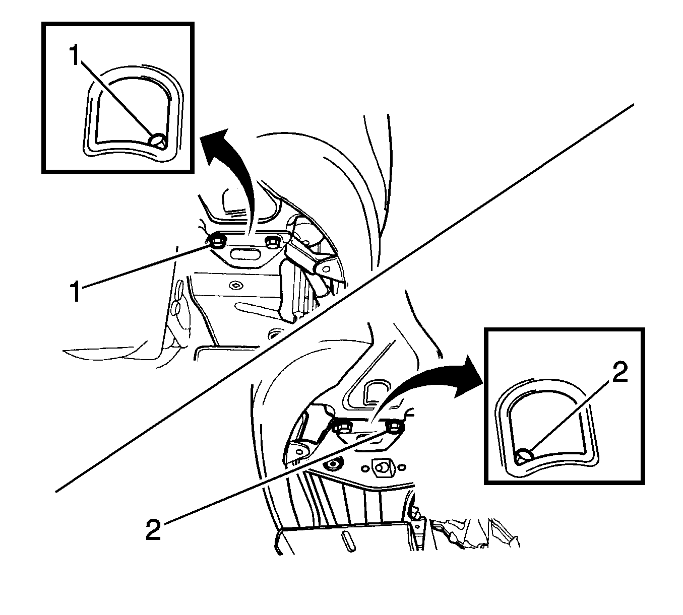
- Install the crossmember and bolts (1, 2) and tighten to 17-27 N·m (13-20 lb ft).
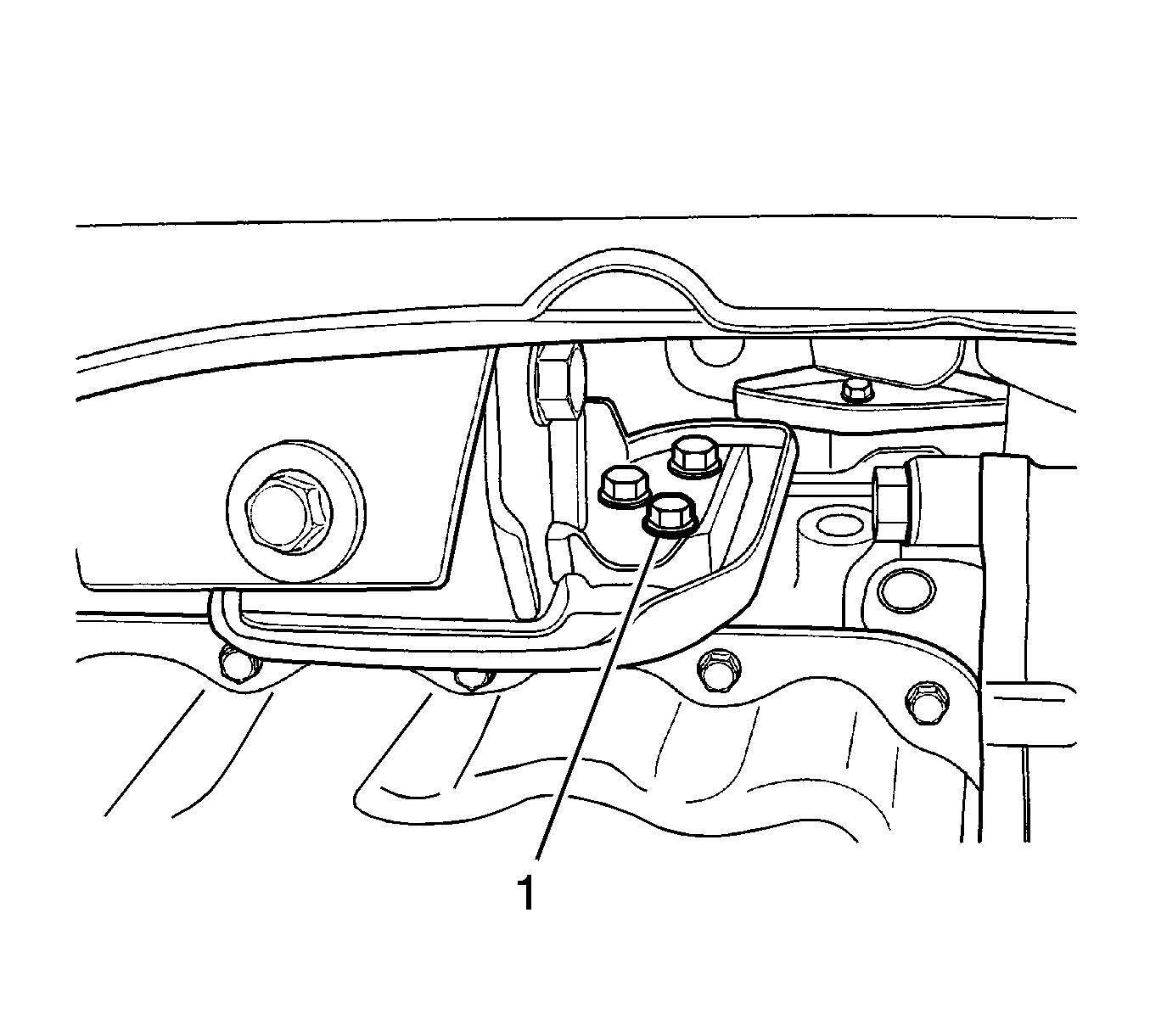
- Install the engine mount front bracket and bolt (1) and tighten to 35-41 N·m (25-30 lb ft).
- Install the damping front bush assembly and bolts (1, 2, 3).
- Install the differential side drive axle.
- Install the wheel side drive axle.
- Install the caulking nut.
- Install the stabilizer bar. Tighten the stabilizer bar castellated nut to 40-50 N·m (30-36 lb ft) and the stabilizer bar mounting bolt to 33-53 N·m (24-39 lb ft).
- Install the left and right front longitudinal member. Tighten the front longitudinal member bolt to 10-14 N·m (7-10.5 lb ft) and the front longitudinal member nut to 60-80 N·m (44-59 lb ft).
- Install the control arm and stud nut (2) and tighten to 50-70 N·m (36-52 lb ft).
- Install the tie rod end and castellated nut (1) and tighten to 35-55 N·m (25-41 lb ft).
- Install both of the front wheels. Refer to Tire and Wheel Removal and Installation.
- Connect the surge tank coolant return hose (1) and heater outlet hose (2).
- Connect the generator B+ terminal (1).
- Connect the starter electrical connector (2).
- Connect oil pressure switch electrical connector (3).
- Connect the electrical wire strap (4).
- Connect the generator electrical connector (5).
- Install the front exhaust pipe, gasket, and bolts. Tighten the front exhaust pipe nuts (1), exhaust manifold side to 25-35 N·m (18-25 lb ft) and the front exhaust pipe nuts (2), muffler pipe side to 25-35 N·m (18-25 lb ft).
- Connect the speedometer cable and vehicle speed sensor electrical connector, if equipped.
- Connect the clutch cable and wire clip (1).
- Install the transaxle under cover and tighten the under-cover bolts (1) to 35-55 N·m (25-41 lb ft).
- Connect the backup lamp switch electrical connector (3).
- Connect the transaxle case ground connection line (1) and bolt (2).
- Install the engine electrical wire-bending strap.
- Connect the select and shift cable (4).
- Install the power steering pump pressure pipes and power steering pressure sensor, if equipped. Tighten the power steering pump pressure pipe nut (1) to 36-50 N·m (26-36 lb ft) and the power steering pump pressure pipe fitting (2) to 21-35 N·m (15-25 lb ft).
- Install the air conditioning low and high pressure pipes, if equipped and tighten the bolts (1) to 23 N·m (17 lb ft).
- Install the radiator (1) and cooling fan (2). Tighten the radiator bolt (1, 2) to 4-5 N·m (35-44 lb in) and the cooling fan bolt (3) to 4-5 N·m (35-44 lb in).
- Install the radiator upper (1), surge tank (2), and lower hose (3).
- Install the power steering oil tank (1), if equipped.
- Install the coolant surge tank (2).
- Connect the coolant temperature sensor connector (1).
- Connect the ECT sensor connector (2).
- Connect the oxygen sensor connector (3).
- Connect the IAC valve connector (4).
- Connect the TP sensor connector (5).
- Connect the CMP sensor connector and the CKP sensor connector.
- Connect the heat core inlet hose.
- Connect the throttle body coolant outlet hose.
- Install the distributor. Refer to Distributor Replacement.
- Install the EVAP canister.
- Connect the throttle cable (1).
- Connect the MAP sensor connector (2).
- Connect the canister solenoid connector (3).
- Connect the brake booster vacuum hose (4).
- Connect the MAP sensor vacuum hose (5).
- Connect the EVAP canister vacuum hose.
- Connect the IAT sensor connector (6).
- Connect the fuel line inlet hose and the fuel injector wire connectors on to the fuel rail.
- Install the air filter, resonator with snorkel assembly. Refer to Air Cleaner Element Replacement.
- Fill and check the following fluids:
- Connect the negative battery cable.
- Reset the engine control module (ECM). Refer to Engine Control Module Replacement.
- Start the engine and check the engine for normal operation.
- Recharge the air conditioning, if equipped.
- Verify that all electrical connectors and hoses are properly secured.
- Check all fluid levels and verify that there are not leaks.
Caution: Refer to Fastener Caution in the Preface section.
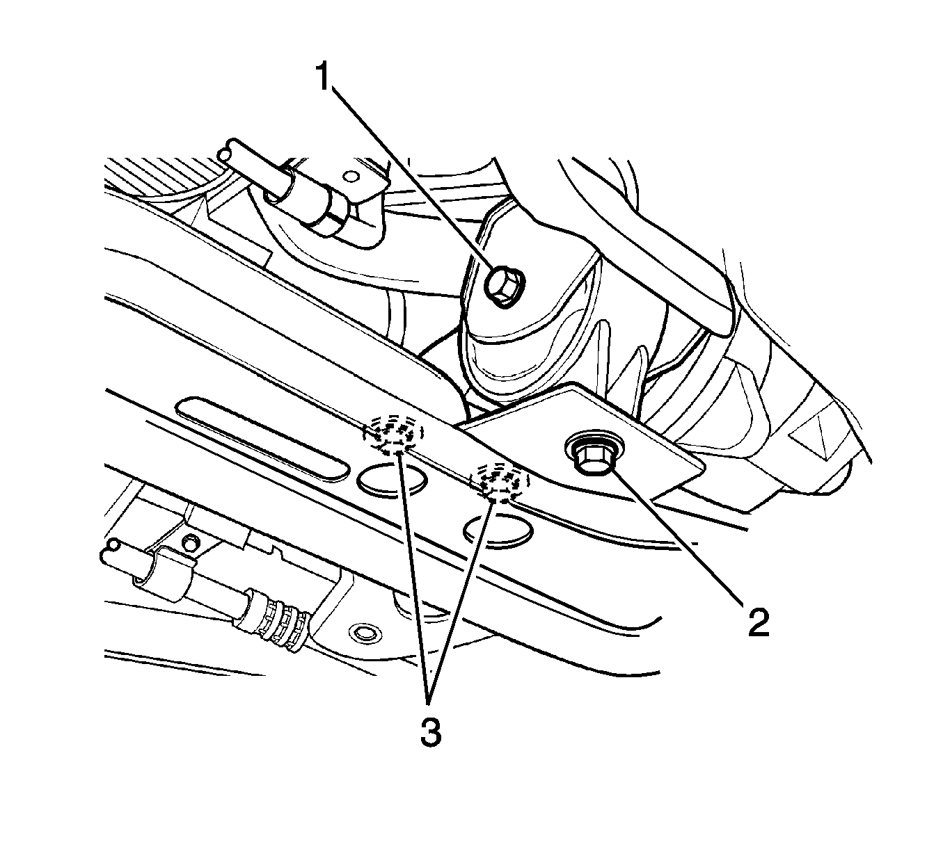
| • | Tighten the crossmember side front damping bush bolt to 35-41 N·m (25-30 lb ft). |
| • | Tighten the crossmember side two front damping bush bolts to 45-55 N·m (33-41 lb ft). |
| • | Tighten the front damping bush bolt and nut to 68-83 N·m (50-62 lb ft). |
Caution: When removing the drive axle, use extreme care not to nick or cut the drive axle oil seal.








| • | Transaxle oil |
| • | Power steering oil |
| • | Radiator coolant |
