Steering Gear Adjustments 708 Model
Before making any adjustments refer to the power steering diagnostics in order to review the possible steering system problems. Adjust the steering gear only as a correction and not as a periodic adjustment. Adjusting the steering gear in the vehicle is not recommended for the following 2 reasons:
| • | The complexity involved in adjusting the worm thrust bearing preload |
| • | The friction effect provided by the hydraulic fluid in the steering gear |
For the proper adjustment, remove the steering gear from the vehicle. Refer to the appropriate procedure:
- Drain the power steering fluid from the gear.
- Mount the gear in a vise.
- Make the following adjustments:
| • | The worm thrust bearing preload |
| • | The pitman shaft over-center preload |
The worm thrust bearing preload is controlled by the amount of compression force exerted on the conical worm bearing thrust races by the adjuster plug.
The pitman shaft over-center preload is controlled by the pitman shaft adjuster screw. The pitman shaft adjuster screw determines the clearance between the rack piston and the pitman shaft sector teeth.
Steering Gear Adjustments 710 Model
If there is not enough room in order to swing the torque wrench through the arc required for the accurate preload measurement, remove the steering gear from the vehicle. Adjust the steering gear on the bench if the steering gear is removed from the vehicle. To adjust the steering gear on the bench refer to Steering Gear Worm Gear Thrust Bearing Preload Adjustment - Off Vehicle . Disregard the steps that pertain to on-vehicle adjustment.
Always check the worm bearing preload adjustment first. Adjust, if necessary, before making the pitman shaft preload over-center adjustment. Refer to Steering Gear Pitman Shaft Over-Center Preload Adjustment - Off Vehicle .
Steering Gear Adjustments High-Point Centering
- Set the front wheels in the straight ahead position. This can be checked by driving the vehicle a short distance on a flat surface.
- Check the position of the mark on the worm shaft designating the steering gear high point.
- Loosen the adjuster tube clamps on both the left and right hand tie rods on models equipped with an independent front suspension, if the steering gear has been moved off the high point when setting the wheel in the straight ahead position.
- Turn both adjuster tubes an equal number of turns in the same direction to bring the gear back on the high point.
- Loosen the adjuster tube clamps on the connecting rod on models equipped with the I-beam front suspension, if the gear has been moved off the high point when setting the wheels in the straight ahead position.
- Turn the adjuster tube to bring the gear back on the highpoint.
- Check and adjust the toe-in. Refer to Front Toe Adjustment .
- Refer to Tie Rod Replacement , and in Steering Linkage for adjuster tube clamping instructions.
Important: The worm shaft mark should be at the top side of the shaft at the 12 o'clock position and lined up with the mark in the coupling lower clamp.
Important: Turning the adjuster tubes an unequal number of turns or in different directions will disturb the toe setting of the wheels.
Steering Gear Adjustments Saginaw - 710 Model
Adjustment Procedure
Tools Required
| • | J 7754-01 Torque Wrench |
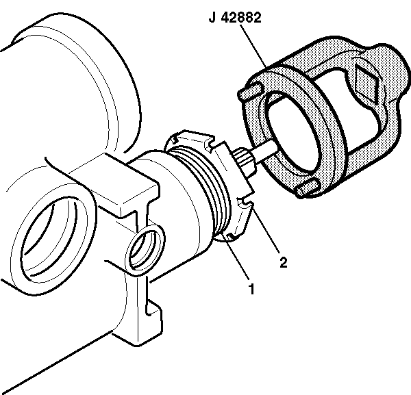
| • | J 42882 Adjuster Nut Socket |
- Drain the oil from the steering gear by rotating the steering gear completely several times.
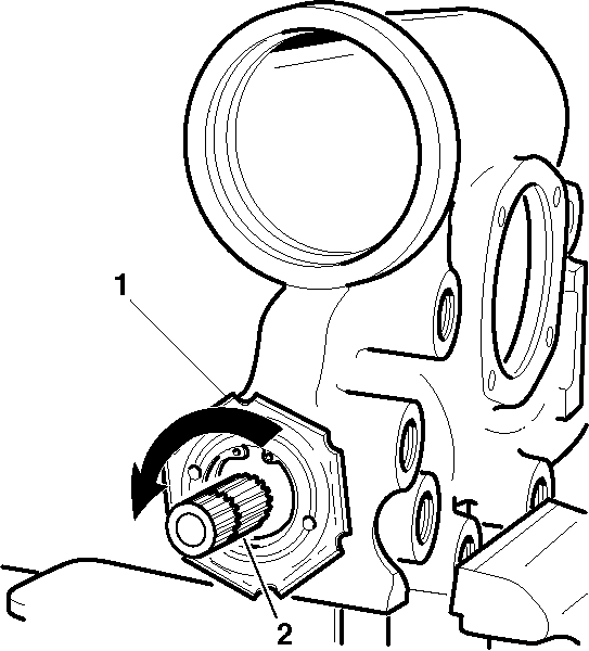
- Turn the stub shaft (1) from the right wheel stop to the left wheel stop while counting the number of turns.
- Rotate the stub shaft (1) back half the number of turns to the center position.
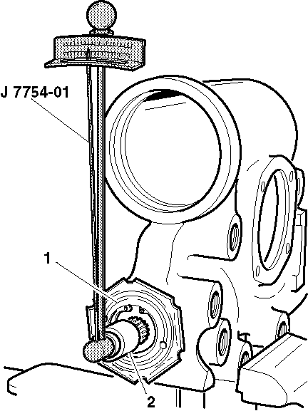
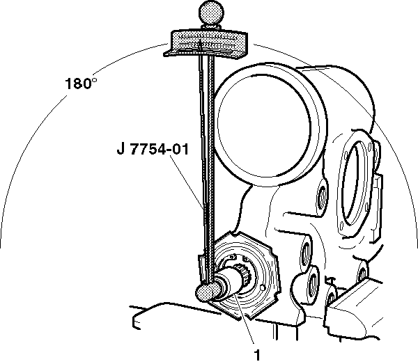
- Place J 7754-01 and a deepwell ¾ inch 12 point socket (1) over the stub shaft in order to check the total preload torque by rotating J 7754-01 through a 180 degree arc either side of the center.
- Record the highest reading while turning J 7754-01 back over the center position.
- Turn the stub shaft ½ turn (180 degrees) right or left from the center.
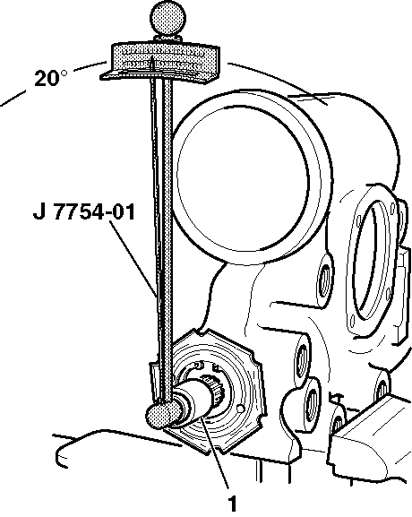
- Install J 7754-01 vertically on the stub shaft.
- Turn J 7754-01 20 degrees to the left or the right of the vertical position.
- Record the reading while turning J 7754-01 back to the vertical position.
- Subtract this reading from the reading in step 5.
- If the reading in step 5 is 0.23 N·m (2 lb in), then the steering gear is adjusted properly. If the reading in step 5 is less than 0.23 N·m (2 lb in) proceed with the following adjustments:
- Loosen the coupling shield retainer and the lock nut with the steering gear centered.
- Turn the adjuster nut assembly (1) clockwise using J 42882 . Torque the adjuster nut assembly (1) to 28-31 N·m (21-23 lb ft) and back off 15-25 degrees.
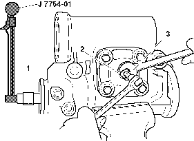
- Tighten the coupling shield and lock nut (2). Stabilize the adjuster nut assembly (1) while tightening the coupling shield and lock nut (2).
- Turn the stub shaft 2 turns right or left from the center position.
- Install J 7754-01 near vertical. Record the torque reading. The torque reading should be 1.60 N·m (14 lb in) while turning J 7754-01 in an arc 20 degrees left or right of the vertical position.
- With the steering gear in the center position, loosen the preload adjuster nut (2). Ensure the adjusting screw is backed out counterclockwise all the way.
- Turn the adjuster screw clockwise ½ turn. This prevents the pitman shaft from bottoming out of the side cover.
- Place J 7754-01 in the vertical position in order to check the preload.
- Move J 7754-01 90 degrees to the left or the right of the center position. Record the highest torque reading while moving J 7754-01 back to the center position.
- Tighten the adjuster screw clockwise until the torque reading is 0.68-1.13 N·m (6-10 N·m) higher than the reading taken in the previous step.
- Tighten the preload adjuster nut (2) to 90 N·m (66 N·m). Ensure the adjuster screw does not turn during tightening.
- Reinspect the preload after tightening the preload adjuster nut (2).
| 11.1. | If the reading in step 5 is at least 0.23 N·m (2 lb in) and not more than 1.13 N·m (10 lb in), the steering gear is adjusted properly. Proceed to steps 12 through 16. |
| 11.2. | If the reading in step 5 is less than 0.23 N·m (2 lb in) or more than 1.13 N·m (10 lb in), proceed to step 12 through 23. |
