Steering Gear Replacement 708 Model (Motor Home Only)
Removal Procedure
- Place a drain pan under the steering gear.
- Disconnect the negative battery cable.
- Remove the hoses from the steering gear.
- Raise the hose up in order to prevent any oil drainage.
- Cap or tape the ends of the hose and the gear fittings in order to prevent contamination.
- Tag the hose locations.
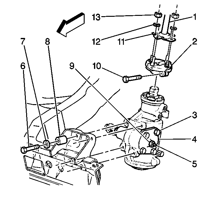
- Remove the coupling pinch bolt (10).
- Mark the relationship of the coupling to the stub shaft.
- Remove the pitman arm. Refer to Pitman Arm Replacement in Steering Linkage.
- Remove the steering gear frame bolts (6).
- Remove the steering gear. Use a soft mallet in order to tap lightly on the coupling in order to remove the steering shaft/coupling from the steering gear stub shaft.
Caution: Unless directed otherwise, the ignition and start switch must be in the OFF or LOCK position, and all electrical loads must be OFF before servicing any electrical component. Disconnect the negative battery cable to prevent an electrical spark should a tool or equipment come in contact with an exposed electrical terminal. Failure to follow these precautions may result in personal injury and/or damage to the vehicle or its components.

Installation Procedure
- Line up the marks made during the removal procedure in order to guide the stub shaft into the coupling/steering shaft assembly.
- For JB8 units, install the steering gear to the frame bolts with the washers.
- Place the steering gear in position.
- Install the steering gear to the frame bolts (6), the spring washers (7), and the spacers (8).
- Install the coupling pinch bolt.
- Install the pitman arm. Refer to Pitman Arm Replacement in Steering Linkage.
- Remove the plugs and the caps from the steering gear and the hoses.
- Install the hoses to the steering gear.
Tighten
Tighten the bolts to 80 N·m (59 lb ft).

Notice: Use the correct fastener in the correct location. Replacement fasteners must be the correct part number for that application. Fasteners requiring replacement or fasteners requiring the use of thread locking compound or sealant are identified in the service procedure. Do not use paints, lubricants, or corrosion inhibitors on fasteners or fastener joint surfaces unless specified. These coatings affect fastener torque and joint clamping force and may damage the fastener. Use the correct tightening sequence and specifications when installing fasteners in order to avoid damage to parts and systems.
Tighten
Tighten the bolts to 87.5 N·m (65 lb ft).
Tighten
Tighten the coupling pinch bolt to 102 N·m (75 lb ft).
Tighten
Tighten the hose fittings to the specifications. Refer to
Fastener Tightening Specifications
.
Steering Gear Replacement 710 Model
Removal Procedure
- Position the front wheels and the steering wheel straight ahead.
- Remove the pitman arm. Refer to Pitman Arm Replacement in Steering Linkage.
- Remove the hydraulic hoses from the steering gear.
- Plug the hoses and the ports in order to prevent contamination.
- Tag the hose locations.
- Remove the cardan joint clamp bolt and the nut.
- Remove the cardan joint from the steering gear stub shaft.
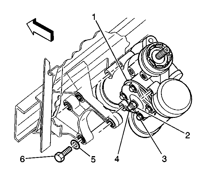
- Remove the steering gear mounting bolts (6), spacers, and the washers (5).
- Remove the steering gear.

Notice: Do not hammer on the pitman arm, pitman arm shaft, or puller. Damage to the pitman or steering gear may result. Pitman arms are non-repairable and must be replaced when damaged or worn.
Notice: Avoid contaminating the power steering system. Cap open hoses and ports to prevent dirt and debris from entering system. Contaminated power steering fluid and dirt can cause early parts failure.
Installation Procedure
- Install the steering gear to the frame rail. Hold the gear in the vertical position (stub shaft up).
- Install the bolts from the directions shown. Install the washers (5) and spacers under the bolt (6) heads.
- Install the pitman arm. Refer to Pitman Arm Replacement in Steering Linkage.
- Install the cardan joint yoke to the steering gear stub shaft.
- Install the cardan joint bolt.
- Adjust the cardan joint installed dimension. Refer to Steering Wheel Replacement in Steering Wheel and Column.
- Install the hydraulic hoses to the steering gear.
- Bleed the system. Refer to Power Steering System Bleeding .

Notice: Use the correct fastener in the correct location. Replacement fasteners must be the correct part number for that application. Fasteners requiring replacement or fasteners requiring the use of thread locking compound or sealant are identified in the service procedure. Do not use paints, lubricants, or corrosion inhibitors on fasteners or fastener joint surfaces unless specified. These coatings affect fastener torque and joint clamping force and may damage the fastener. Use the correct tightening sequence and specifications when installing fasteners in order to avoid damage to parts and systems.
Tighten
Tighten the bolts to 240 N·m (177 lb ft).
Tighten
Tighten the nut to 370 N·m (275 lb ft).
Tighten
Tighten the bolt to 48 N·m (35 lb ft).
Tighten
Tighten the hoses to 38 N·m (28 lb ft).
Steering Gear Replacement 708 Model (I-Beam Front Axle)
Removal Procedure
- Place a drain pan under the steering gear.
- Disconnect the negative battery cable.
- Remove the hoses from the steering gear.
- Raise the hose up in order to prevent any oil drainage.
- Cap or tape the ends of the hose and the gear fittings in order to prevent contamination.
- Tag the hose locations.
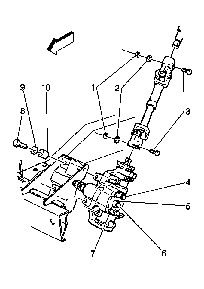
- Remove the lower cardan type joint pinch bolt (3).
- Mark the relationship of the universal yoke to the stub shaft.
- Remove the pitman arm. Refer to Pitman Arm Replacement in Steering Linkage.
- Remove the steering gear frame bolts (8).
- Remove the steering gear.
- Use a soft mallet in order to tap lightly on the cardan joint yoke in order to remove the cardan joint from the steering gear stub shaft.
Caution: Unless directed otherwise, the ignition and start switch must be in the OFF or LOCK position, and all electrical loads must be OFF before servicing any electrical component. Disconnect the negative battery cable to prevent an electrical spark should a tool or equipment come in contact with an exposed electrical terminal. Failure to follow these precautions may result in personal injury and/or damage to the vehicle or its components.

Installation Procedure
- Place the steering gear in position.
- Line up the marks made during the removal procedure in order to guide the stub shaft into the cardan type joint assembly.
- Install the steering gear to the frame bolts (8), the spring washers (9) and the spacers (10).
- Install the intermediate shaft pinch bolt (3).
- Install the pitman arm. Refer to Pitman Arm Replacement in Steering Linkage.
- Remove the plugs and the caps from the steering gear and the hoses.
- Install the hoses to the steering gear.

Notice: Use the correct fastener in the correct location. Replacement fasteners must be the correct part number for that application. Fasteners requiring replacement or fasteners requiring the use of thread locking compound or sealant are identified in the service procedure. Do not use paints, lubricants, or corrosion inhibitors on fasteners or fastener joint surfaces unless specified. These coatings affect fastener torque and joint clamping force and may damage the fastener. Use the correct tightening sequence and specifications when installing fasteners in order to avoid damage to parts and systems.
Tighten
Tighten the bolts to 87.5 N·m (65 lb ft).
Tighten
Tighten the pinch bolt to 102 N·m (75 lb ft).
The pinch bolt (3) must pass through the shaft undercut.
Tighten
Tighten the hose fittings to the specifications. Refer to
Fastener Tightening Specifications
.
Steering Gear Replacement 708 (Except I-Beam Front Axle)
Removal Procedure
- Place a drain pan under the steering gear.
- Disconnect the negative battery cable.
- Remove the hoses from the steering gear.
- Raise the hose up in order to prevent any oil drainage.
- Cap or tape the ends of the hose and the gear fittings in order to prevent contamination.
- Tag the hose locations.
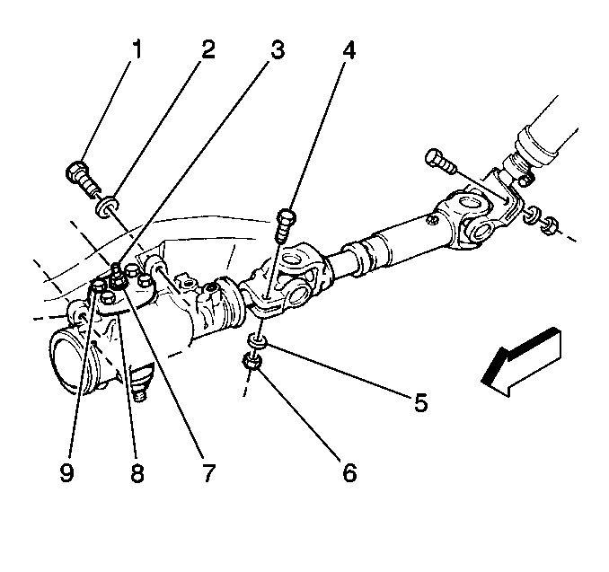
- Remove the lower cardan type joint pinch bolt (4).
- Mark the relationship of the universal yoke to the stub shaft.
- Remove the pitman arm. Refer to Pitman Arm Replacement in Steering Linkage.
- Remove the steering gear frame bolts (1) and washers (2).
- Remove the steering gear.
- Use a soft mallet in order to tap lightly on the cardan joint yoke in order to remove the cardan joint from the steering gear stub shaft.
Caution: Unless directed otherwise, the ignition and start switch must be in the OFF or LOCK position, and all electrical loads must be OFF before servicing any electrical component. Disconnect the negative battery cable to prevent an electrical spark should a tool or equipment come in contact with an exposed electrical terminal. Failure to follow these precautions may result in personal injury and/or damage to the vehicle or its components.

Installation Procedure
- Place the steering gear in position.
- Line up the marks made during the removal procedure in order to guide the stub shaft into the cardan type joint assembly.
- Install the steering gear to the frame bolts (1) and the spring washers (2).
- Install the intermediate shaft pinch bolt (4).
- Install the pitman arm. Refer to Pitman Arm Replacement in Steering Linkage.
- Remove the plugs and the caps from the steering gear and the hoses.
- Install the hoses to the steering gear.

Notice: Use the correct fastener in the correct location. Replacement fasteners must be the correct part number for that application. Fasteners requiring replacement or fasteners requiring the use of thread locking compound or sealant are identified in the service procedure. Do not use paints, lubricants, or corrosion inhibitors on fasteners or fastener joint surfaces unless specified. These coatings affect fastener torque and joint clamping force and may damage the fastener. Use the correct tightening sequence and specifications when installing fasteners in order to avoid damage to parts and systems.
Tighten
Tighten the bolts to 87.5 N·m (65 lb ft).
Tighten
Tighten the pinch nut to 102.5 N·m (76 lb ft).
The pinch bolt (4) must pass through the shaft undercut.
Tighten
Tighten the hose fittings to the specifications. Refer to
Fastener Tightening Specifications
.
