Tie Rod Replacement Commercial
Removal Procedure
Tools Required
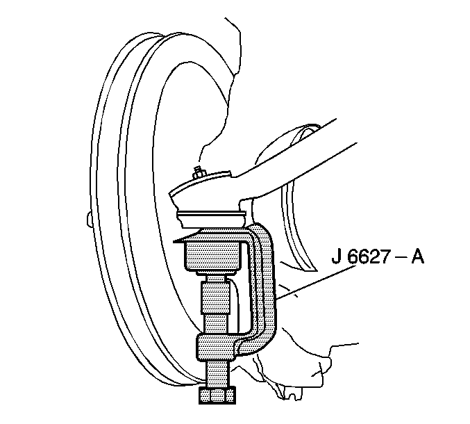
J 6627-A Tie Rod Puller/Wheel Stud Remover
- Before undertaking any service, note the position of the tie rod adjuster tube, and the direction from which the bolts are installed. The tie rod adjuster tube components (1) may be rusted:
- Raise and support the vehicle. Refer to Lifting and Jacking the Vehicle in General Information.
- Remove the cotter pins and the castellated nuts from the outer tie rod ball studs.
- Use the J 6627-A in order to remove the outer tie rod ball studs from the steering knuckle.
- Use the J 6627-A in order to remove the inner tie rod ball studs from the relay rod.
- Loosen the clamp bolts from the tie rod end adjuster tubes.
- Remove the tie rod ends by unscrewing the tie rod ends from the adjuster tubes.
- Clean the following components:

| • | If the torque required in order to remove the nut from the bolt exceeds 9 N·m (80 lb in), discard the nuts and the bolts. |
| • | Apply penetrating oil between the clamp and the tube. |
| • | Rotate the clamps until they move freely. |
| • | Install all parts, with the correct part number, in the proper position. |
Notice: Do not attempt to disconnect a steering linkage joint by driving a wedge between the joint and the attached part. Seal damage may result which will cause premature failure of the joint.

| • | The tapered surfaces |
| • | The threads on the ball stud |
| • | The threads in the ball stud nut |
Installation Procedure
Tools Required
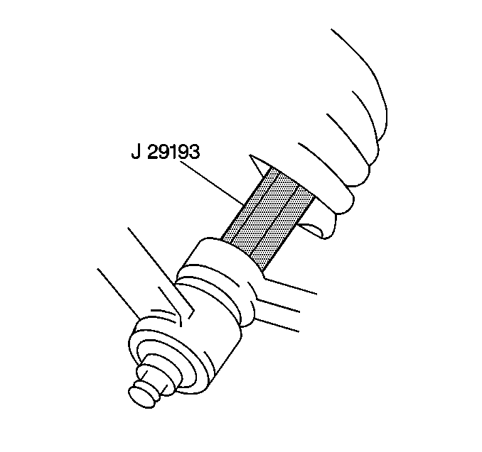
| • | J 29193 Steering Linkage Installer (12 mm) |
| • | J 29194 Steering Linkage Installer (14 mm) |
- If you removed the tie rod ends, lubricate the tie rod threads with chassis lubricant. Refer to Fluid and Lubricant Recommendations in Maintenance and Lubrication.
- Install the tie rod ends to the adjuster tube.
- Install the inner tie rod ball studs to the relay rod.
- Tighten the J 29193 or the J 29194 to 54 N·m (40 lb ft) in order to seat the tapers.
- Remove the J 29193 or the J 29194 .
- Install the prevailing torque nut to the inner tie rod ball stud.
- Install the outer tie rod ball studs to the steering knuckle (4).
- Install the castellated nuts and the cotter pins to the outer tie rod ball studs.
- Adjust the toe-in. Refer to Front Toe Adjustment .
- Position the clamps on the adjuster tubes between the locating dimples (1) and clear of the dimples at either end of the adjuster tube before tightening the nuts.
- Position the clamps within the angular travel as shown with the rearward rotation (2) of 45 degrees. The slot (1) of the adjuster tube must not be within the area (3) of the clamp jaws.
- Ensure that both outer tie rod ends rotate throughout the full travel of the outer tie rod end.
- Maintain the position of each tie rod end while you tighten the clamps in order to ensure free movement of each joint.
- Ensure that the gap next to the adjuster tube (1) is NOT less than 0.127 mm (0.005 in).
- The clamp ends may touch when the nuts are tightened to specifications.
- Lower the vehicle.

The number of threads on both the inner and the outer rod ends must be equal within 3 threads.
Ensure that the seal is on the stud.

Notice: Use the correct fastener in the correct location. Replacement fasteners must be the correct part number for that application. Fasteners requiring replacement or fasteners requiring the use of thread locking compound or sealant are identified in the service procedure. Do not use paints, lubricants, or corrosion inhibitors on fasteners or fastener joint surfaces unless specified. These coatings affect fastener torque and joint clamping force and may damage the fastener. Use the correct tightening sequence and specifications when installing fasteners in order to avoid damage to parts and systems.
Tighten
Tighten the torque nut to 90 N·m (66 lb in).
Refer to
Fastener Tightening Specifications
.
Tighten
Tighten the castellated nuts to 62 N·m (46 lb ft).
Refer to
Fastener Tightening Specifications
.


Tighten
Tighten the adjuster tube clamp bolts to 68 N·m (50 lb ft).
Tie Rod Replacement Motorhome
Removal Procedure
Tools Required
J 6627-A Tie Rod Puller/Wheel Stud Remover
- Before undertaking any service, note the position of the tie rod adjuster tube, and the direction from which the bolts are installed. The tie rod assembly (6) adjuster tube components may be rusted:
- Raise and support the vehicle. Refer to Lifting and Jacking the Vehicle in General Information.
- Remove the cotter pins and the castellated nuts from the outer tie rod ball studs.
- Use the J 6627-A in order to remove the outer tie rod ball studs from the steering knuckle.
- Use the J 6627-A in order to remove the inner tie rod ball studs from the relay rod.
- Loosen the clamp bolts from the tie rod end adjuster tubes.
- Remove the tie rod ends by unscrewing the tie rod ends from the adjuster tubes.
- Clean the following components:

| • | If the torque required in order to remove the nut from the bolt exceeds 9 N·m (80 lb in), discard the nuts and the bolts. |
| • | Apply penetrating oil between the clamp and the tube. |
| • | Rotate the clamps until they move freely. |
| • | Install all parts, with the correct part number, in the proper position. |
Notice: Do not attempt to disconnect a steering linkage joint by driving a wedge between the joint and the attached part. Seal damage may result which will cause premature failure of the joint.

| • | The tapered surfaces |
| • | The threads on the ball stud |
| • | The threads in the ball stud nut |
Installation Procedure
Tools Required
| • | J 29193 Steering Linkage Installer (12 mm) |
| • | J 29194 Steering Linkage Installer (14 mm) |
- If you removed the tie rod ends, lubricate the tie rod threads with chassis lubricant. Refer to Fluid and Lubricant Recommendations Maintenance and Lubrication.
- Install the tie rod ends to the adjuster tube.
- Install the inner tie rod ball studs to the relay rod.
- Tighten the J 29193 or the J 29194 to 54 N·m (40 lb ft) in order to seat the tapers.
- Remove the J 29193 or the J 29194 .
- Install the prevailing torque nut to the inner tie rod ball stud.
- Install the outer tie rod ball studs to the steering knuckle (7).
- Install the castellated nuts and the cotter pins to the outer tie rod ball studs.
- Adjust the toe-in. Refer to Front Toe Adjustment in Wheel Alignment.
- Position the clamps on the adjuster tubes between the locating dimples (1)and clear of the dimples at either end of the adjuster tube before tightening the nuts.
- Position the clamps within the angular travel as shown with rearward rotation (2) of 45 degrees. The slot (1) of the adjuster tube must not be within the area (3) of the clamp jaws.
- Ensure that both outer tie rod ends rotate throughout the full travel of the outer tie rod end.
- Maintain the position of each tie rod end while you tighten the clamps in order to ensure free movement of each joint.
- Ensure that the gap next to the adjuster tube (1) is NOT less than 0.127 mm (0.005 in).
- The clamps ends may touch when the nuts are tightened to specifications.
- Lower the vehicle.

The number of threads on both the inner and the outer rod ends must be equal within 3 threads.
Ensure that the seal is on the stud.

Notice: Use the correct fastener in the correct location. Replacement fasteners must be the correct part number for that application. Fasteners requiring replacement or fasteners requiring the use of thread locking compound or sealant are identified in the service procedure. Do not use paints, lubricants, or corrosion inhibitors on fasteners or fastener joint surfaces unless specified. These coatings affect fastener torque and joint clamping force and may damage the fastener. Use the correct tightening sequence and specifications when installing fasteners in order to avoid damage to parts and systems.
Tighten
Tighten the nut to 90 N·m (66 lb in). Refer
to
Fastener Tightening Specifications
.
Tighten
Tighten the nuts to 62 N·m (46 lb ft). Refer
to
Fastener Tightening Specifications
.


Tighten
Tighten the adjuster tube clamp bolts to 68 N·m (50 lb ft).
Tie Rod Replacement Commercial (I-Beam Front Axle)
Removal Procedure
Tools Required
J 6627-A Tie Rod Puller/Wheel Stud Remover
- Raise and support the vehicle. Refer to Lifting and Jacking the Vehicle in General Information.
- Remove the cotter pins and the castellated nuts from the outer tie rod ball studs.
- Remove the shock absorber (4) from the tie rod assembly (6) and frame.
- Use the J 6627-A in order to remove the tie rod ball studs from the steering knuckles.
- Clean the following components:
- Inspect the tie rod assembly components. Refer to Tie Rod End Inspection .
Notice: Do not attempt to disconnect a steering linkage joint by driving a wedge between the joint and the attached part. Seal damage may result which will cause premature failure of the joint.


| • | The tapered surfaces |
| • | The threads on the ball stud |
| • | The threads in the ball stud nut |
Installation Procedure
Tools Required
| • | J 29193 Steering Linkage Installer (12 mm) |
| • | J 29194 Steering Linkage Installer (14 mm) |
- Lubricate the tie rod threads with chassis lubricant. Refer to Fluid and Lubricant Recommendations .
- Tighten the J 29193 or the J 29194 to 54 N·m (40 lb ft) in order to seat the tapers.
- Remove the J 29193 or the J 29194 .
- Install the tie rod assembly (6) to the steering knuckles.
- Install the castellated nuts and the cotter pins to the tie rod ball studs.
- Install the shock absorber (4) to the tie rod assembly (6).
- Adjust the toe-in. Refer to Wheel Alignment Specifications . When the wheel toe-in reading corresponds to the recommended wheel toe-in figure, tighten the two adjustment nuts (2) on the tie rod.
- Lower the vehicle.


Notice: Use the correct fastener in the correct location. Replacement fasteners must be the correct part number for that application. Fasteners requiring replacement or fasteners requiring the use of thread locking compound or sealant are identified in the service procedure. Do not use paints, lubricants, or corrosion inhibitors on fasteners or fastener joint surfaces unless specified. These coatings affect fastener torque and joint clamping force and may damage the fastener. Use the correct tightening sequence and specifications when installing fasteners in order to avoid damage to parts and systems.
Tighten
Tighten the nut to 220 N·m (162 lb in). Refer
to
Fastener Tightening Specifications
.
Tighten
Tighten the nuts to 62 N·m (46 lb ft). Refer
to
Fastener Tightening Specifications
.
Important: When replacing a tie rod assembly, the wheel toe-in adjustment nuts of a new tie rod assembly are only hand tightened and must be tightened to the proper torque upon installation with the wheel toe-in reading corresponding to the recommended wheel toe-in specification.
Tighten
Tighten the first nut and the jam nut (closest to shock absorber connection)
to 375 N·m (277 lb ft).
