For 1990-2009 cars only
Steering Column Tilt Head Replacement Right Hand
Tools Required
| • | J 23653-SIR Lock Plate Compressor |
| • | J 42137 Lock Plate Compressor Adapter |
Removal Procedure
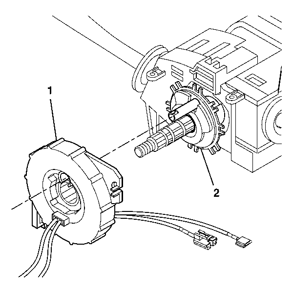
- Remove the SIR coil. Refer to Inflatable Restraint Steering Wheel Module Coil Replacement in SIR.
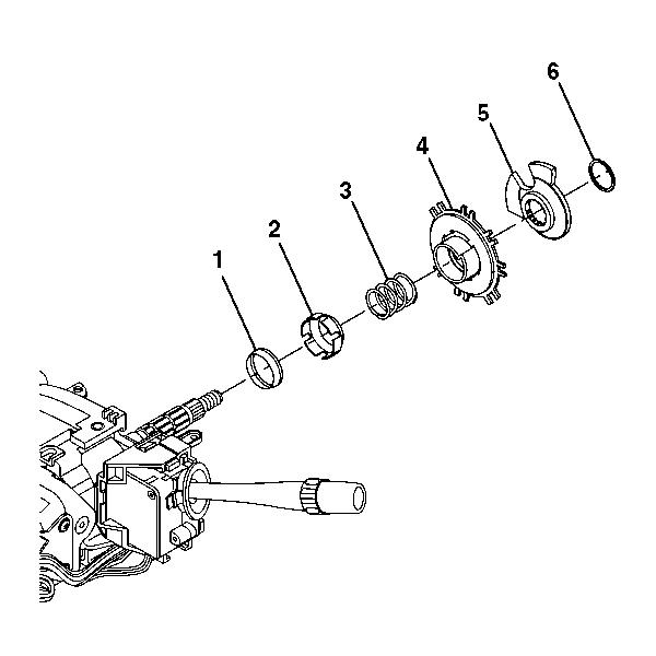
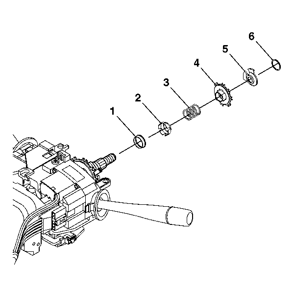
- Remove the bearing retainer (6) using J 23653-SIR and J 42137 . Dispose of the bearing retainer (6).
- Remove the cam orientation plate (5).
- Remove the turn signal cancel cam assembly (4).
- Remove the upper bearing spring (3).
- Remove the upper bearing inner race seat (2).
- Remove the inner race (1).
- Remove the steering shaft and tilt head as an assembly. Refer to Lower Bearing and Steering Column Jacket Replacement .
- Remove the tilt head from the steering shaft.
Installation Procedure
- Install the tilt head to the steering shaft.
- Install the steering shaft and tilt head as an assembly. Refer to Lower Bearing and Steering Column Jacket Replacement .
- Install the inner race (1).
- Install the upper bearing inner race seat (2).
- Install the upper bearing spring (3).
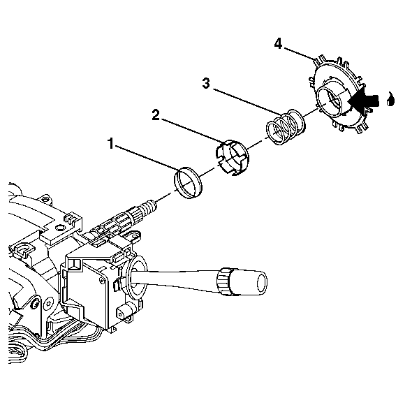
- Lubricate the turn signal cancel cam assembly (4) with GM P/N 12377900 (Canadian P/N 10953529) and install.
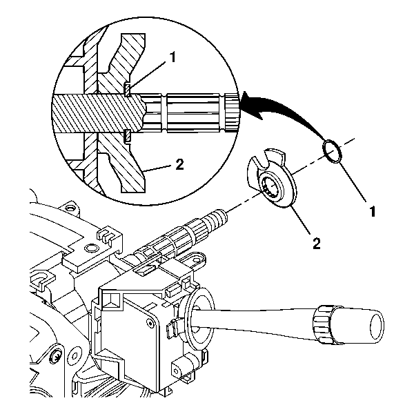
- Install the cam orientation plate (2).
- Install the new bearing retainer (1) using J 23653-SIR and J 42137 . Firmly seat the bearing retainer (1) in the groove on the race and upper shaft assembly.
- Install the SIR coil. Refer to Inflatable Restraint Steering Wheel Module Coil Replacement in SIR.
Steering Column Tilt Head Replacement Power Tilt and Telescope
Tools Required
| • | J 23653-SIR Lock Plate Compressor |
| • | J 42137 Lock Plate Compressor Adapter |
Removal Procedure
- Remove the SIR coil. Refer to Inflatable Restraint Steering Wheel Module Coil Replacement in SIR.
- Remove the bearing retainer (6) using J 23653-SIR and J 42137 . Dispose of the bearing retainer.
- Remove the cam orientation plate (5).
- Remove the turn signal cancel cam assembly (4).
- Remove the upper bearing spring (3).
- Remove the upper bearing inner race seat (2).
- Remove the inner race (1).
- Remove the steering shaft and tilt head as an assembly. Refer to Lower Bearing and Steering Column Jacket Replacement .
- Remove the tilt head from the steering shaft.
Installation Procedure
- Install the tilt head to the steering shaft.
- Install the steering shaft and tilt head as an assembly. Refer to Lower Bearing and Steering Column Jacket Replacement .
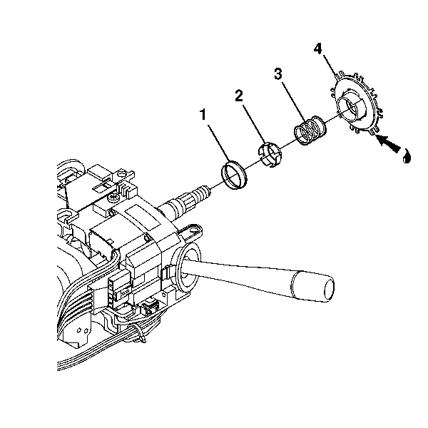
- Install the inner race (1).
- Install the upper bearing inner race seat (2).
- Install the upper bearing spring (3).
- Install the turn signal cancel cam assembly (4). Lubricate the assembly with GM P/N 12377900 (Canadian P/N 10953529).
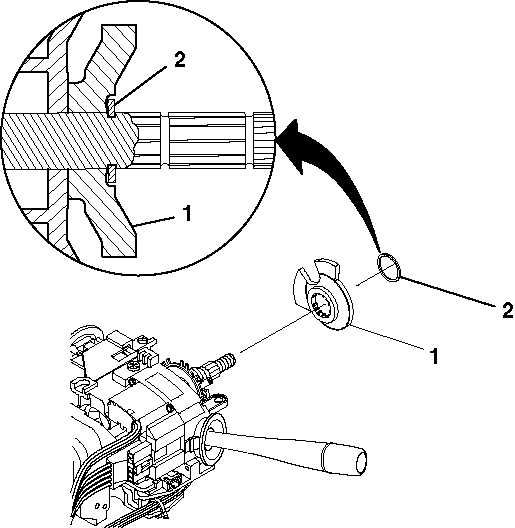
- Install the cam orientation plate (2).
- Install the new bearing retainer (1) using J 23653-SIR . Firmly seat the bearing retainer in the groove on the upper shaft assembly.
- Install the SIR coil. Refer to Inflatable Restraint Steering Wheel Module Coil Replacement in SIR.
Steering Column Tilt Head Replacement Manual Tilt
Tools Required
| • | J 23653-SIR Lock Plate Compressor |
| • | J 42137 Lock Plate Compressor Adapter |
Removal Procedure
- Remove the upper and lower trim covers. Refer to Steering Column Trim Covers Replacement .
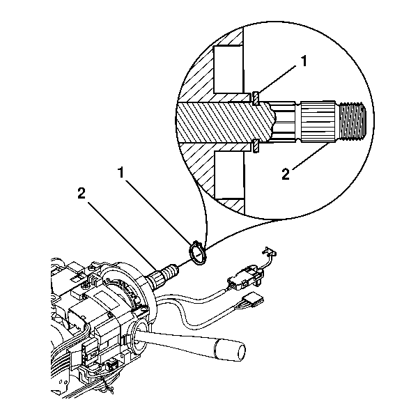
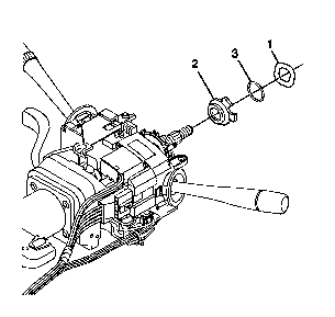
- Remove the retaining ring (1) from the race and upper shaft assembly (2).
- Remove the SIR coil (1) from the race and upper shaft assembly (2). Let the coil hang freely.
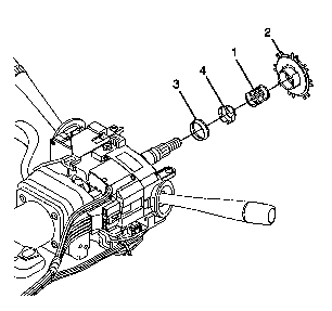
- Remove the wave washer (1).
- Remove the bearing retainer (3) using J 23653-SIR and J 42137 . Dispose of the bearing retainer.
- Remove the cam orientation plate (2).
- Remove the turn signal cancel cam assembly (2).
- Remove the upper bearing spring (1).
- Remove the upper bearing inner race seat (4).
- Remove the inner race (3).
- Remove the steering shaft and tilt head as an assembly. Refer to Lower Bearing and Steering Column Jacket Replacement .
- Remove the tilt head from the steering shaft.
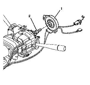
Important: The SIR coil will become uncentered if the following conditions occur:
• The steering column is separated from the steering gear and allowed
to rotate. • The centering spring is pushed down, letting the hub rotate while the
SIR coil is removed from the steering column.
Installation Procedure
- Install the tilt head to the steering shaft.
- Install the steering shaft and tilt head as an assembly. Refer to Lower Bearing and Steering Column Jacket Replacement .
- Install the inner race (3).
- Install the upper bearing inner race seat (4).
- Install the upper bearing spring (1).
- Install the turn signal cancel cam assembly (2).
- Install the cam orientation plate (2).
- Install the new bearing retainer (3) using J 23653-SIR and J 42137 . Firmly seat the bearing retainer in the groove on the race and upper shaft assembly.
- Install the wave washer (1).
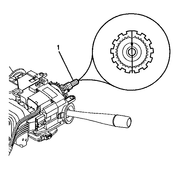
- To install the SIR coil, align the block tooth on the race and upper shaft assembly (1) to the 12 o'clock position.
- Ensure that the SIR coil is centered. If you reuse the original coil, refer to Inflatable Restraint Steering Wheel Module Coil Centering .
- Align the SIR coil (1) with the horn tower on the turn signal cancel cam assembly (2) and install the coil.
- Install the retaining ring (1) onto the race and upper shaft assembly (2) using J 23653-SIR . Securely seat the retaining ring (1) in the groove on the race and upper shaft assembly (2).
- Install the upper and lower trim covers. Refer to Steering Column Trim Covers Replacement .


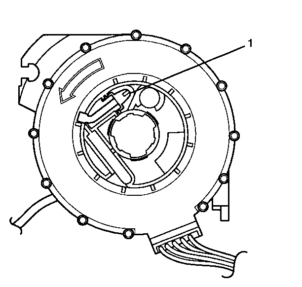
| 11.1. | Depress the tab (1) on the back of the SIR coil and rotate the center of the coil 6 revolutions. Follow the direction of the black arrow. |
| 11.2. | Turn the center of the SIR coil 2.5 revolutions in the opposite direction from the previous step. |
