Removal Procedure
Tools Required
| • | J 37088-A Fuel Line Quick Connect Separator |
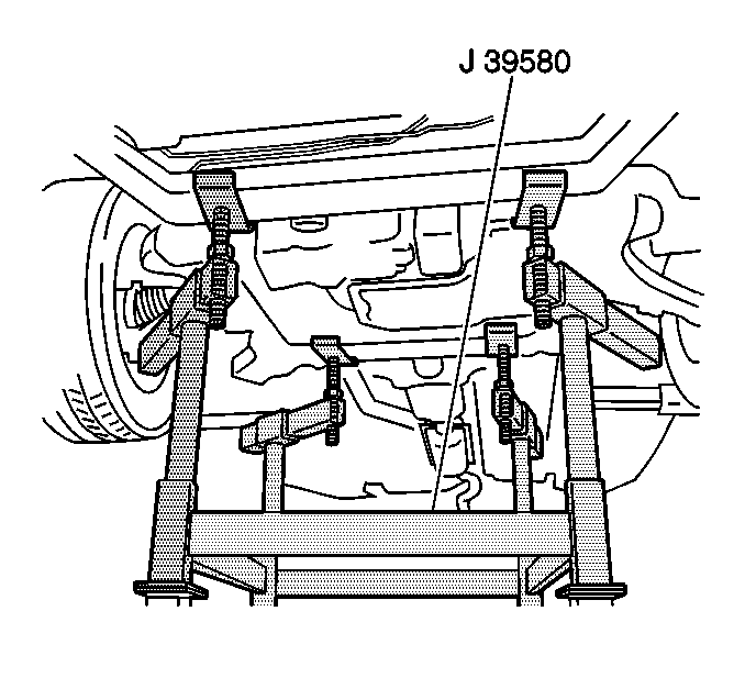
| • | J 39580 Universal Engine Support Table |
- Disable the SIR. Refer to Disabling the SIR System in SIR.
- Recover the A/C Refrigerant System. Refer to Refrigerant Recovery and Recharging in Heating and Air Conditioning.
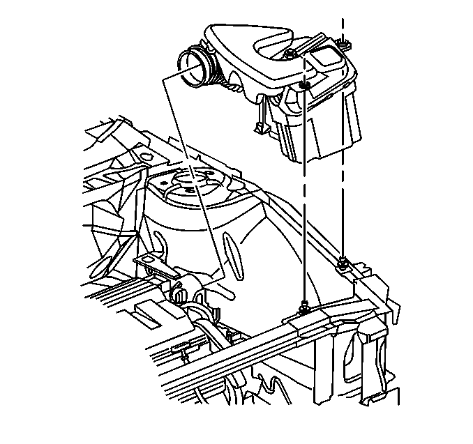
- Remove the air intake duct.
- Remove the air cleaner assembly. Refer to Air Cleaner Assembly Replacement in Engine Controls.
- Drain the cooling system. Refer to Cooling System Draining and Filling in Engine Cooling.
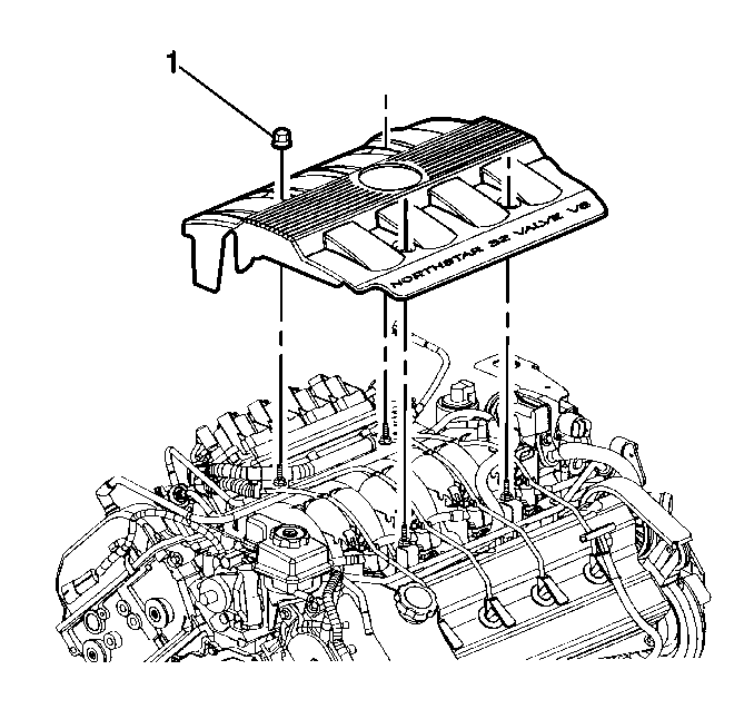
- Remove the engine cover.
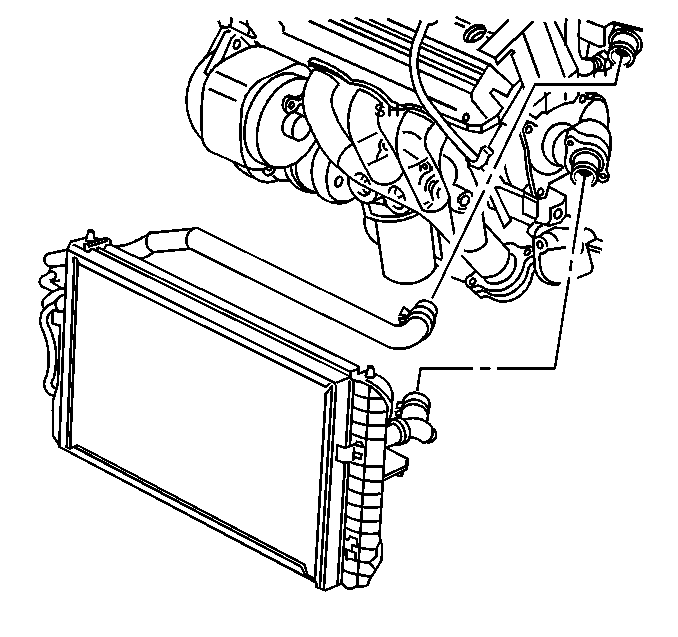
- Remove the radiator hose at the crossover.
- Remove the upper radiator hose from the engine.
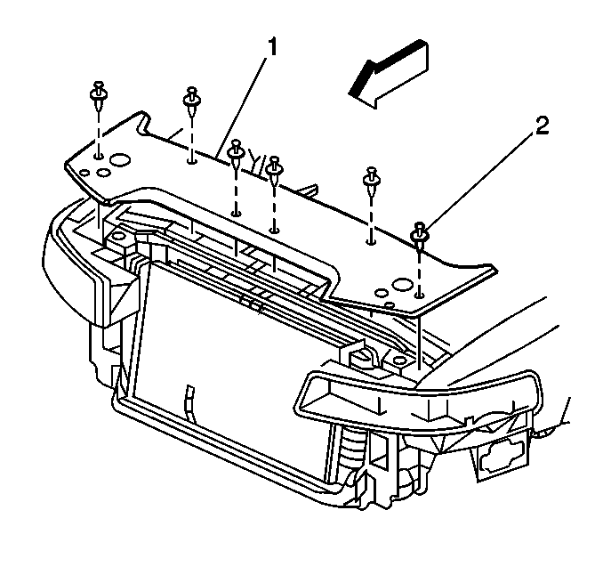
- Remove the radiator upper cover.
- Remove the cooling fans. Refer to Engine Coolant Fan Motor Replacement in Engine Cooling.
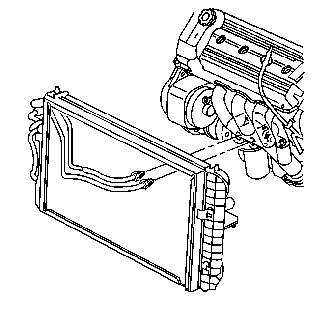
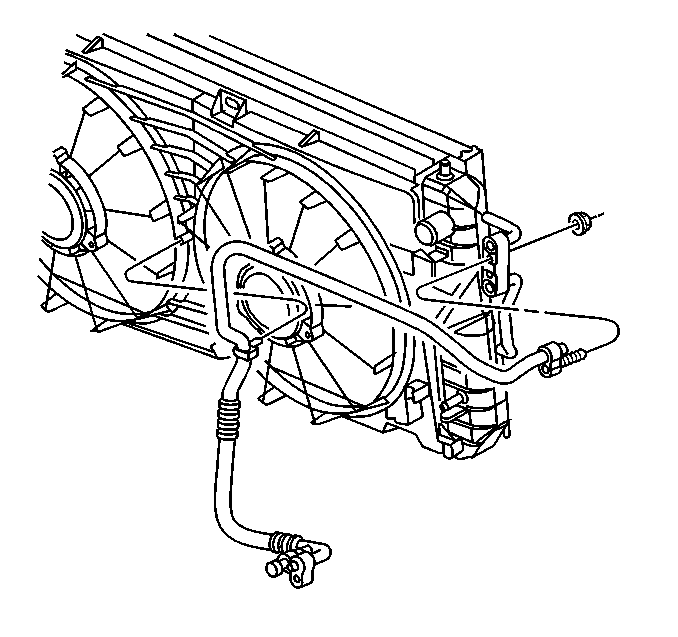
- Remove the transmission cooler lines from the radiator.
- Disconnect the coolant overflow hose.
- Remove the radiator and A/C condenser assembly.
- Remove the cruise control servo connections.
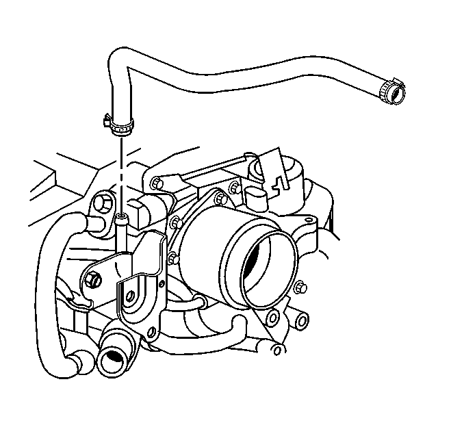
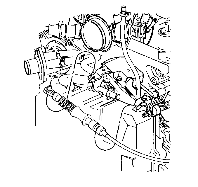
- Remove the throttle and cruise control cables from the throttle body. Refer to Accelerator Control Cable Replacement in Engine Controls.
- Remove the brake pressure switch and bracket.
- Disconnect the brake master cylinder. Refer to Master Cylinder Replacement in Hydraulic Brakes.
- Remove the shift cable from the manual shift lever and the bracket.
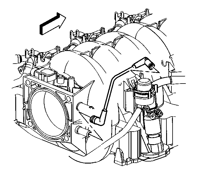
- Remove the vacuum hose from the brake booster.
- Using the J 37088-A fuel line quick connect separator disconnect the fuel inlet and return the lines.
- Remove the negative battery cable from the left cylinder head.
- Disconnect the A/C suction hose from the compressor.
- Disconnect the A/C discharge hose from the compressor.
- Disconnect the electrical harness from the underhood relay center.
- Disconnect the electrical pass through by the brake booster.
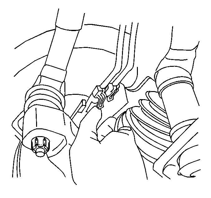
- Disconnect the right and left road sensing suspension electrical connectors.
- Raise and support the vehicle. Refer to Lifting and Jacking the Vehicle in General Information.
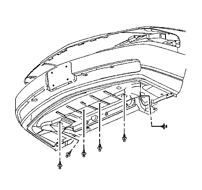
- Remove the lower engine splash shield. Refer to Body.
- Remove the right and left wheels. Refer to Tire and Wheel Removal and Installation in Tires and Wheels.
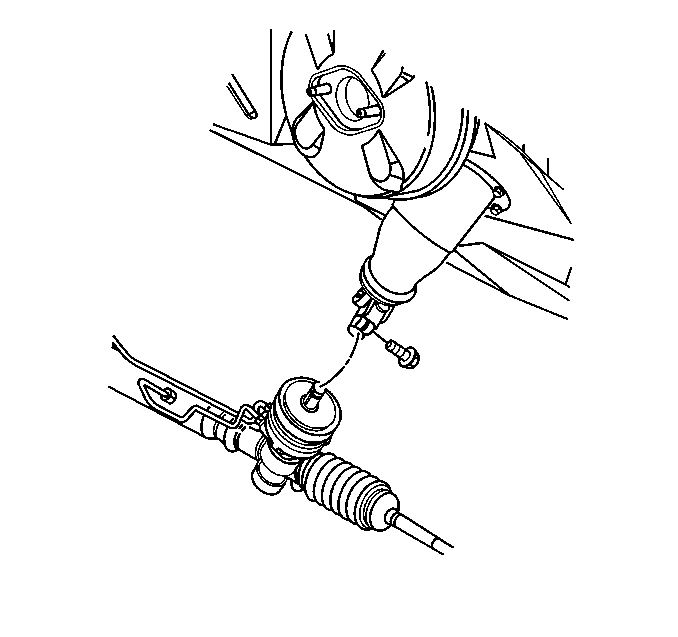
- Disconnect the steering gear intermediate shaft.
- Disconnect the wheel speed and brake wear sensors.
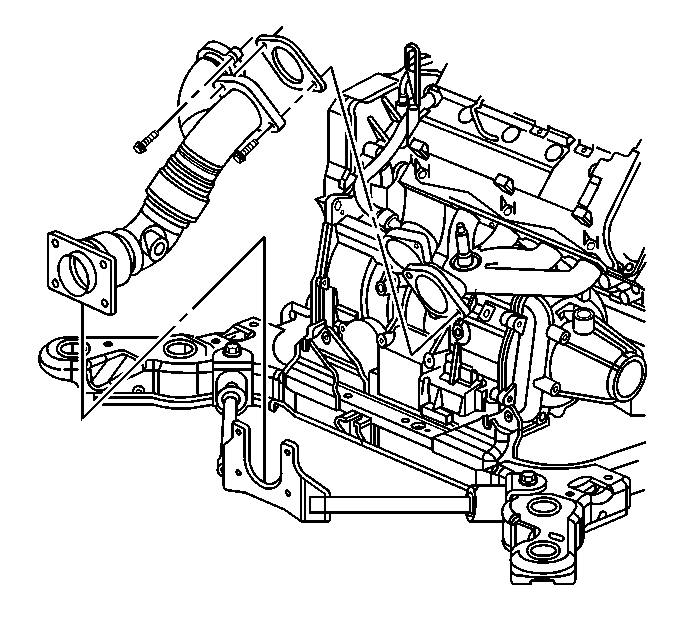
- Disconnect the exhaust downpipe from the exhaust manifold.
- Disconnect the brake line at the proportioning valves. Refer to Brakes.
- Disconnect the oxygen sensors electrical connectors.
- Lower the vehicle.
- Remove the right and left road sensing suspension wheel speed harness brackets.
- Remove the front and rear engine mount nuts.
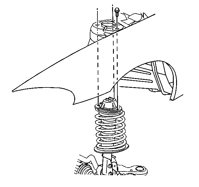
- Remove the strut to tower bolts at each strut tower.
- Position J 39580 powertrain support dolly under engine assembly.
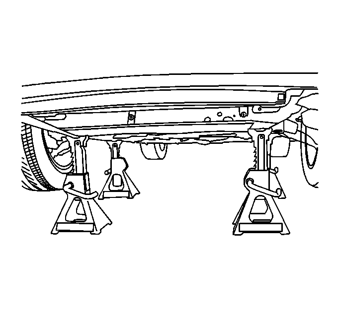
- If the powertrain support dolly is unavailable. Support the powertrain with four suitable jackstands.
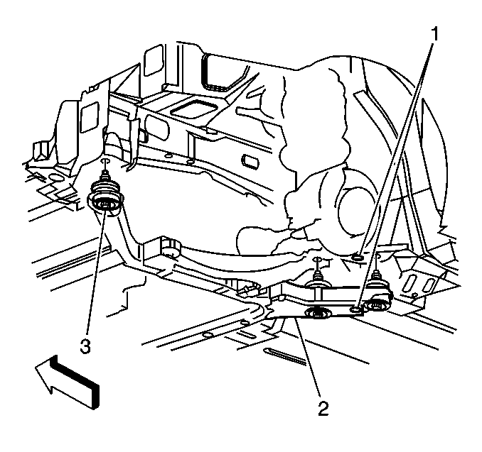
- Remove the six frame mount bolts (3).
- Raise the vehicle slowly.
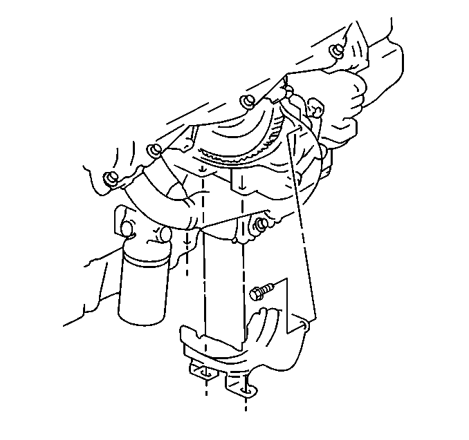
- Remove the flywheel inspection cover.
- Disconnect the torque converter from the flywheel
- Attach an engine lift to the engine.
- Disconnect the left engine mount from the frame. Refer to Engine Mount Replacement .
- Remove the engine to transaxle bracket.
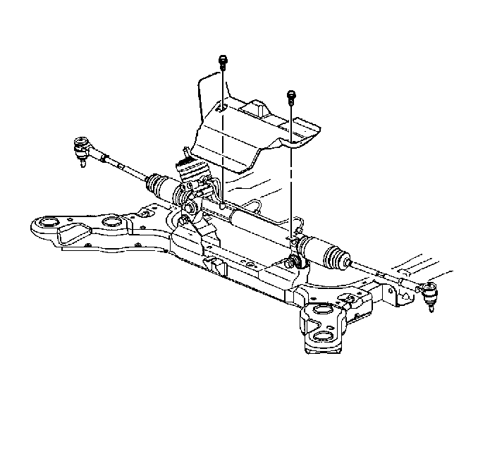
- Remove the power steering gear heat shield.
- Remove the power steering gear and set aside. Refer to Steering Gear Replacement in Power Steering System.
- Disconnect the right engine mount to frame.
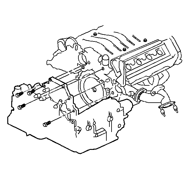
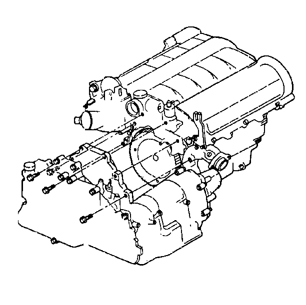
- Remove the transaxle to engine bolts.
- Raise engine from the frame and transaxle assembly.
- Transfer necessary parts as required.
Caution: Unless directed otherwise, the ignition and start switch must be in the OFF or LOCK position, and all electrical loads must be OFF before servicing any electrical component. Disconnect the negative battery cable to prevent an electrical spark should a tool or equipment come in contact with an exposed electrical terminal. Failure to follow these precautions may result in personal injury and/or damage to the vehicle or its components.

Installation Procedure
- Install the engine to transmission and frame assembly.
- Install four transmission (bell housing) to engine bolts.
- Install the right engine mount bracket to the engine.
- Install the power steering gear to the frame. Refer to Steering Gear Replacement Power Steering System.
- Install the power steering gear heat shield.
- Install the engine to transmission bracket and bolts.
- Connect the left engine mount to frame nut.
- Remove the engine lift from the engine.
- Install the torque converter to the flywheel.
- Install the flywheel inspection cover.
- Position the powertrain under the vehicle.
- Carefully lower the vehicle and align the powertrain.
- Install six body frame bolts. Refer to Frame Replacement in Frame and Underbody.
- Install the strut tower bolts.
- Install the front and rear engine mount nuts.
- Connect the right and left road sensing suspension brackets.
- Raise and support the vehicle. Refer to Lifting and Jacking the Vehicle in General Information.
- Connect two oxygen sensor connections.
- Connect the brake line at the proportioning valves.
- Install the exhaust downpipe to exhaust manifolds.
- Connect wheel speed sensor and brake sensor electrical connections.
- Install power steering gear to intermediate shaft pinch bolt.
- Install front engine splash shield with six push-in fasteners.
- Install right and left wheels.
- Lower the vehicle.
- Install the right and left road sensing suspension electrical connection.
- Connect the electrical pass through by the brake booster.
- Install the upper radiator hose to the engine.
- Install the radiator hose to the crossover.
- Connect the electrical harness to the relay center.
- Connect the A/C discharge line to the compressor.
- Connect the A/C suction line to the compressor.
- Connect the negative battery cable to the generator.
- Connect the fuel lines. Refer to Fuel Hose/Pipes Replacement - Filter to Engine in Engine Controls.
- Connect the brake booster vacuum hose.
- Connect the shift cable at the transaxle.
- Connect the brake master cylinder. Refer to Master Cylinder Replacement in Hydraulic Brakes.
- Install the brake pressure switch and bracket.
- Connect the throttle and cruise cables.
- Connect the coolant overflow hoses.
- Install the radiator and condenser assembly. Refer to Radiator Replacement in Engine Cooling.
- Connect the forward discriminating sensor.
- Install the upper radiator support cover.
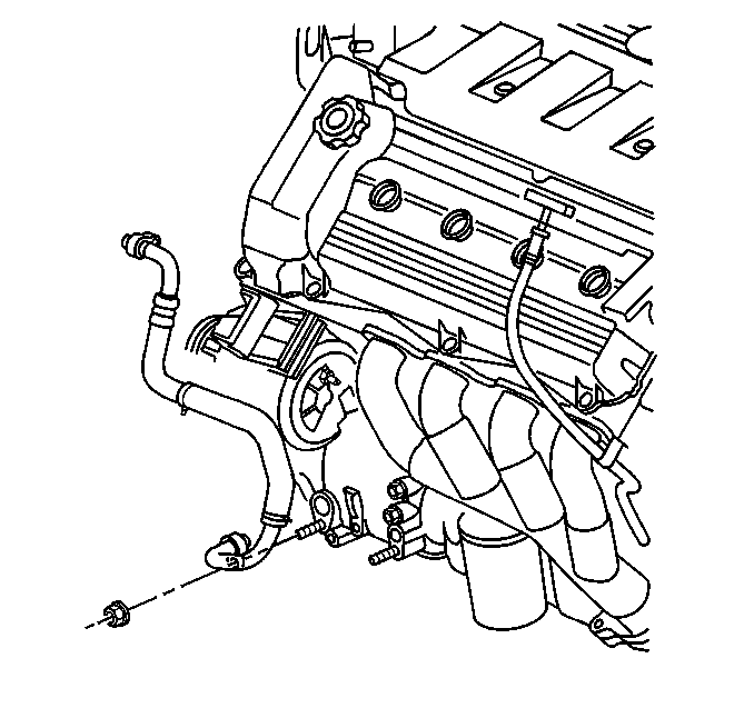
- Install the engine cover and four nuts (1).
- Install the air cleaner cover and PCM connector.
- Install the air intake duct.
- Recharge the A/C system. Refer to Refrigerant Recovery and Recharging in Heating and Air Conditioning.
- Fill the coolant system. Refer to Cooling System Draining and Filling in Engine Cooling.
- Enable the SIR. Refer to Enabling the SIR System in SIR.
- Bleed the power steering system. Refer to Power Steering System Bleeding in Power Steering Systems.
- Bleed the brakes. Refer to Bleeding Brakes in Brakes.
Notice: Use the correct fastener in the correct location. Replacement fasteners must be the correct part number for that application. Fasteners requiring replacement or fasteners requiring the use of thread locking compound or sealant are identified in the service procedure. Do not use paints, lubricants, or corrosion inhibitors on fasteners or fastener joint surfaces unless specified. These coatings affect fastener torque and joint clamping force and may damage the fastener. Use the correct tightening sequence and specifications when installing fasteners in order to avoid damage to parts and systems.
Tighten
Tighten the bolts to 75 N·m (55 lb ft).


Tighten
Tighten the bolts to 47 N·m (35 lb ft).


Tighten
Tighten the strut tower bolts to 48 N·m (35 lb ft).

Tighten
Tighten nuts to 40 N·m (30 lb ft).


Tighten
Tighten the bolt to 40 N·m (30 lb ft).

Tighten
Tighten wheel nuts to 140 N·m (100 lb ft).


Tighten
Tighten the line to 22 N·m (16 lb in).

Tighten
Tighten the line to 22 N·m (16 lb in).


