Tools Required
| • | J 28467-A Engine Support Fixture |
| • | J 28467-450 Engine Support Fixture Adapter |
| • | J 36857 Lift Brackets |
Removal Procedure
- Disconnect the negative battery cable. Refer to Battery Negative Cable Disconnection and Connection in Engine Electrical.
- Raise and support the vehicle. Lifting and Jacking the Vehicle in General Information.
- Remove the lower oil pan. Refer to Lower Oil Pan Replacement .
- Remove the engine mount lower nuts from the frame bracket.
- Remove the engine splash shield bolts.
- Remove the engine splash shield.
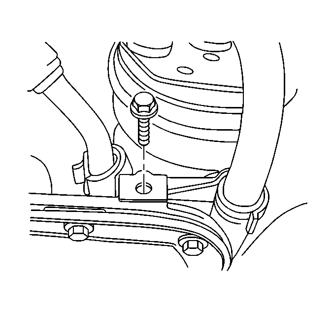
- Remove the A/C compressor hose and ground strap bolt from the front of the upper oil pan.
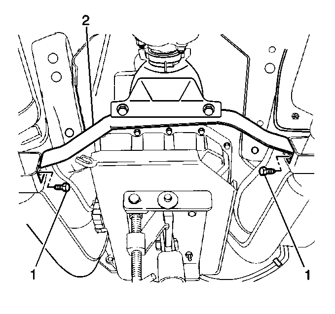
- Remove the catalytic converter hanger bolts (1) from the hanger bracket (2).
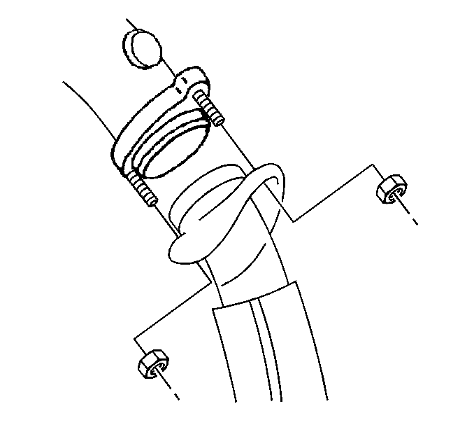
- Remove the catalytic converter nuts from the exhaust manifold.
- Lower the catalytic converters and secure with mechanic wire.
- Remove the 2 idler arm bolts from the frame and lower the relay rod out of the way.
- Lower the vehicle.
- Use the J 28467-A , the J 28467-450 and theJ 36857 to support and raise the engine.
- Raise the vehicle.
- Install jack stands to the engine frame assembly.
- Remove the 4 rear frame bolts.
- Loosen the 2 front frame bolts. DO NOT remove.
- Using the jack stands lower the engine frame assembly.
- Remove the 4 transmission bolts from the upper oil pan.
- Remove all but the 4 corner upper oil pan bolts.
- Loosen the 4 corner upper oil pan bolts.
- Remove the 4 remaining bolts from the upper oil pan.
- Remove the rubber seal (1).
- Clean the upper oil pan mating surfaces.
- Clean oil pan in washing unit, dry with compressed air.
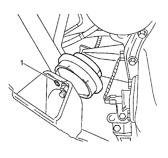
Note the orientation of the alignment tab (1).
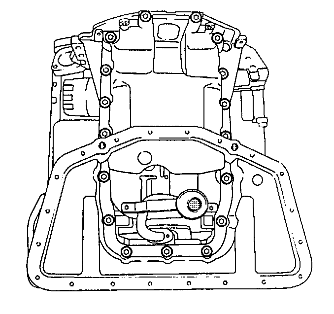
Important: Remove the upper oil pan toward the front of the vehicle. If the oil pan cannot be removed from the block, use a soft faced hammer and tap on the upper oil pan.
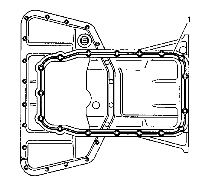
Important: Make sure that no silicone residues or particles remain in the engine block or the upper oil pan.
Installation Procedure
Important: Sealing surfaces need to be clean and dry.
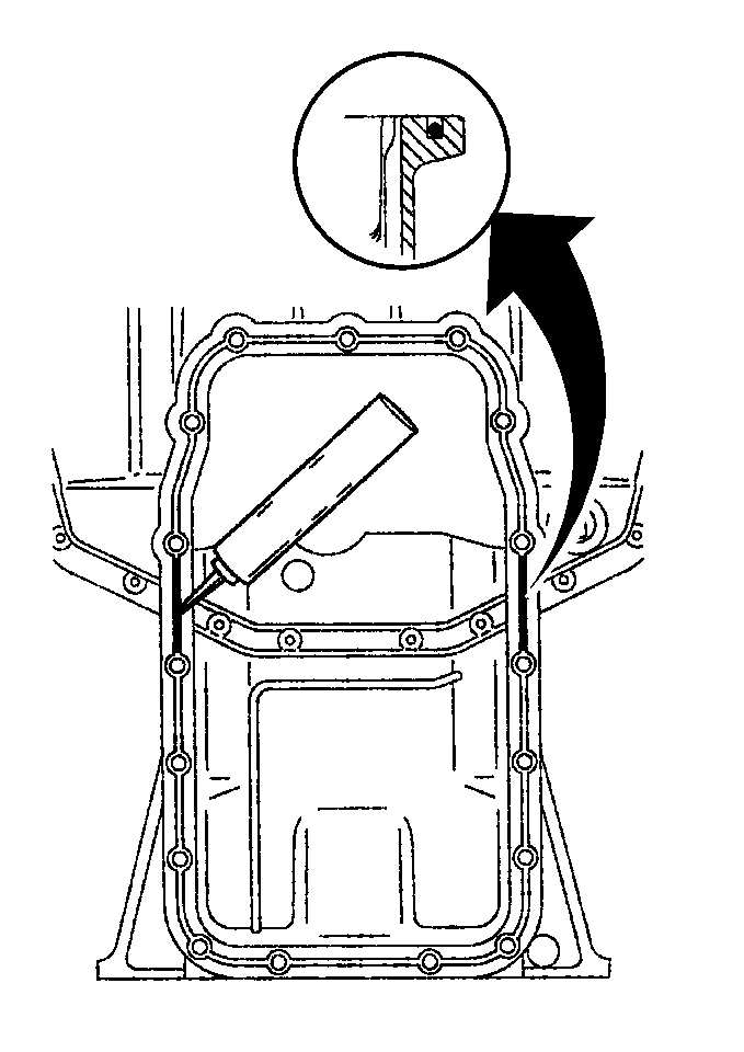
- Apply a 3 mm (0.12 in) bead of silicone sealing compound, GM P/N 12346286 or equivalent, around the upper oil pan.
- Apply a bead of sealant to the joints of the rear crankshaft bearing cap.
- Carefully install the upper oil pan through the front of the vehicle.
- Install the upper oil pan bolts.
- Using the jack stands, raise the engine frame assembly to the original position.
- Install the 4 rear frame bolts.
- Remove the jack stands from the engine frame assembly.
- Lower the vehicle.
- Using the engine support fixture, lower the engine into place.
- Remove the engine support fixture.
- Raise the vehicle.
- Install the 4 transmission bolts to the upper oil pan.
- Raise the relay rod and install the bolts to the right idler arm.
- Raise the catalytic converters into place and install the catalytic converter nuts.
- Install the catalytic converter bolts (1) into the hangers (2).
- Install the A/C compressor hose strap bolt to the upper oil pan.
- Install the engine mount lower nuts. Note the orientation of the locator tab (1).
- Install the lower oil pan. Refer to Lower Oil Pan Replacement .
- Install the splash shield.
- Install the splash shield bolts.
- Lower the vehicle.
- Fill the crankcase with engine oil. Refer to Engine Oil and Oil Filter Replacement .
- Inspect for leaks.
Important: Use care when applying sealant not to carry over sealant to the bolt holes.
Important: Installation of the upper oil pan must be carried out within 5 to 10 minutes of applying the sealant.
Notice: Use the correct fastener in the correct location. Replacement fasteners must be the correct part number for that application. Fasteners requiring replacement or fasteners requiring the use of thread locking compound or sealant are identified in the service procedure. Do not use paints, lubricants, or corrosion inhibitors on fasteners or fastener joint surfaces unless specified. These coatings affect fastener torque and joint clamping force and may damage the fastener. Use the correct tightening sequence and specifications when installing fasteners in order to avoid damage to parts and systems.
Tighten
Tighten the upper oil pan bolts to 15 N·m (11 lb in).
Tighten
| • | Tighten the front bolts to 65 N·m (48 lb ft). |
| • | Tighten the rear bolts to 150 N·m (111 lb ft). |
Ensure the motor mounts are properly aligned.

Tighten
Tighten the upper oil pan bolts to 40 N·m (30 lb ft).
Tighten
Tighten the right idler arm bolts to 60 N·m (44 lb ft).

Tighten
Evenly tighten the catalytic converter nuts to 25 N·m (18 lb ft).

Tighten
Tighten the catalytic converter bolts to 20 N·m (15 lb ft).

Tighten
Tighten the A/C compressor hose strap bolt to 8 N·m (71 lb in).

Tighten
Tighten the engine mount lower nuts to 55 N·m (41 lb ft).
Tighten
Tighten the engine splash shield bolts to 10 N·m (89 lb in).
