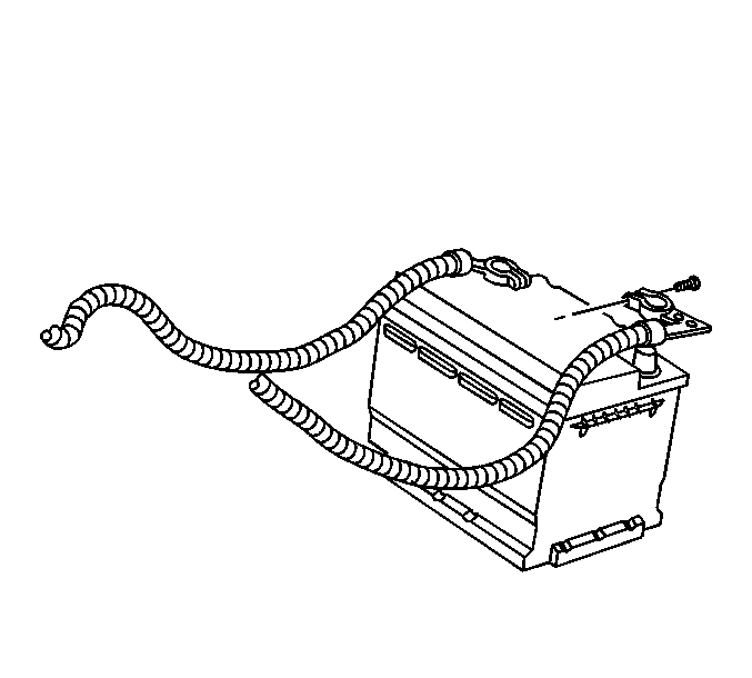
Important: Clean any existing corrosion from the battery terminal , the battery
cable clamp bolt and the battery cable clamp.
- Install the battery ground (negative) cable to the battery.
Notice: Use the correct fastener in the correct location. Replacement fasteners
must be the correct part number for that application. Fasteners requiring
replacement or fasteners requiring the use of thread locking compound or sealant
are identified in the service procedure. Do not use paints, lubricants, or
corrosion inhibitors on fasteners or fastener joint surfaces unless specified.
These coatings affect fastener torque and joint clamping force and may damage
the fastener. Use the correct tightening sequence and specifications when
installing fasteners in order to avoid damage to parts and systems.
- Install the battery
cable clamp bolt to the battery ground (negative) cable clamp.
Tighten
Tighten the battery cable clamp bolt to 6 N·m (53 lb in).
Important: The engine will run extremely poor if the Electronic Throttle Control
is not reprogrammed after a power loss.
- Electronic Throttle Control (ETC):
| 3.1. | Turn the ignition switch to the RUN position. DO NOT start the
engine. |
| 3.2. | Leave the ignition switch in the RUN position for at least three
minutes to allow the ETC to cycle and re-learn its home position. |
| 3.3. | Turn the ignition switch to OFF. |
| 3.4. | Start the engine and allow to run for at least 30 seconds. |
- Power Sunroof:
| 4.1. | Turn the ignition switch to the RUN position. |
| 4.2. | Turn the power sunroof switch to the closed position. After the
sunroof fully closes and the motor stops, press and hold in the switch for
three seconds. |
| 4.3. | Turn the power sunroof switch to the tilt position. After the
sunroof reaches the tilt position and the motor stops, press and hold in the
switch for three seconds. |
| 4.4. | Turn the power sunroof switch to the full open position. After
the sunroof is fully open and the motor stops, press and hold in the switch
for three seconds. |
| 4.5. | Turn the power sunroof switch to the closed position. After the
sunroof fully closes and the motor stops, press and hold in the switch for
three seconds. |
- Power Windows:
| 5.1. | Repeat these steps for each window. |
| 5.2. | Turn the ignition switch to the RUN position. |
| 5.3. | Press the power window switch to the down position. After the
window is in the full down position, press and hold the switch in the down
position for three seconds. |
| 5.4. | Press the power window switch to the up position. After the window
is in the full up position, press and hold the switch in the up position for
three seconds. |
- Heat and A/C Control Head:
| 6.1. | Turn the ignition switch to the RUN position. |
| 6.2. | Simultaneously press the AUTO and OFF buttons (located on the
heat and A/C control head) for at least five seconds. |
| 6.3. | After initiation, the stepper motors will cycle from one stop
to the other. You may hear the motors cycling while calibrating. |
- Power seat memory, power mirror memory and radio channel preset
memory:
| 7.1. | The power seat and power mirror memory are stored in non-volatile
memory in the seat memory module. |
Reprogramming will not be necessary after a power loss. However, if
a component of the seat or mirror is replaced, the module will require programming
with the scan tool.
| 7.2. | The radio channel presets are stored in non-volatile memory in
the radio. |
Reprogramming will not be necessary after a power loss. However, if
the radio is replaced, the station presets must be manually reset.

