Tools Required
| • | J 42069 Timing Belt Alignment Kit |
| • | J 35268-A Camshaft/Front Main Seal Installer |
| • | J 36660-A Torque Angle Meter |
Removal Procedure
- Disconnect the negative battery cable. Refer to Battery Negative Cable Disconnection and Connection in Engine Electrical.
- Remove the intake plenum. Refer to Intake Plenum Replacement .
- Remove the intake air resonator. Refer to Intake Air Resonator Replacement in Engine Controls - 3.0L (L81).
- Remove the left camshaft cover. Refer to Camshaft Cover Replacement - Left Side .
- Remove the timing belt cover. Refer to Timing Belt Cover Replacement .
- Remove the timing belt. Refer to Timing Belt Replacement .
- As a precaution, rotate the crankshaft counterclockwise to the 60 degrees BTDC position to prevent valve/piston contact.
- Insert the J 42069-2 into the camshaft gears.
- Loosen the camshaft gear bolt.
- Remove the J 42069-2.
- Remove the camshaft gear bolt. Discard the bolt.
- Remove the camshaft gear.
- Loosen the camshaft bearing cap bolts sequentially starting from the center and moving outwards in a spiral direction.
- Remove the camshaft bearing cap bolts.
- Remove the camshaft bearing caps. Note the code marks on the bearing caps (R1, R2, R3, etc.).
- Remove the camshaft with seal attached.
- Remove the camshaft seal.
- Clean all of the bearing surfaces.
- Clean all of the sealing surfaces.
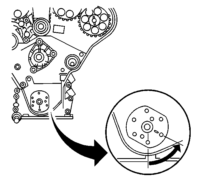
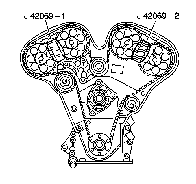

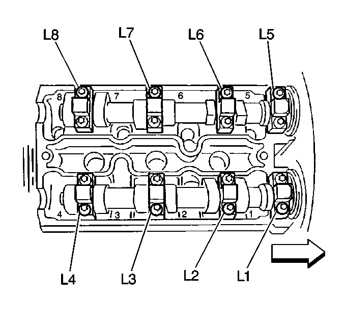
The bearing caps for the drivers side cylinder head is marked with an R, followed by a number.
Installation Procedure
- Lubricate the camshaft bearing surfaces with GM P/N 1052367 or equivalent.
- Install the camshaft to the cylinder head.
- Apply a small amount of Loctite® 573 or equivalent on the forward edge of the front bearing caps to ensure an adequate seal between the bearing cap and the cylinder head.
- Install the camshaft bearing caps in their appropriate position.
- Install the camshaft bearing cap bolts.
- Coat the lip of the camshaft seal with a small amount of GM P/N 12377985, chassis grease or equivalent, to aid in installation.
- Use the J 35268-A to tap the camshaft seal into place.
- Install the camshaft gear bolt.
- Use J 42069-2, to hold the camshaft gear and the camshaft in place while tightening the camshaft gear bolt.
- Tighten the camshaft gear bolt to 50 N·m (37 lb ft).
- Return the crankshaft to TDC.
- Install the timing belt. Refer to Timing Belt Replacement .
- Install the front timing belt cover. Refer to Timing Belt Cover Replacement .
- Install the left camshaft cover. Refer to Camshaft Cover Replacement - Left Side .
- Install the intake plenum. Refer to Intake Plenum Replacement .
- Install the intake air resonator. Refer to Intake Air Resonator Replacement in Engine Controls - 3.0L (L81).
- Connect the negative battery cable. Refer to Battery Negative Cable Disconnection and Connection in Engine Electrical.
Important: Ensure the pin on the exhaust camshaft is approximately in the 12 o'clock position and/or that the pin on the intake camshaft is approximately in the 7 o'clock position to allow for minimal load on the camshaft when installing the bearing caps.
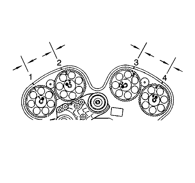
Camshaft Identification
| • | The intake is marked with green paint between bearings 2 & 3 and has a code A cast into it near the number one bearing surface. |
| • | The exhaust is marked with gray paint between bearings 2 & 3 and has a code E cast into it near the number one bearing surface. |
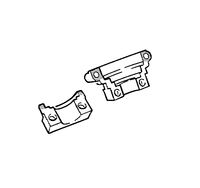
Important: DO NOT allow the sealer to get into the oil journal of the cap.
Notice: Use the correct fastener in the correct location. Replacement fasteners must be the correct part number for that application. Fasteners requiring replacement or fasteners requiring the use of thread locking compound or sealant are identified in the service procedure. Do not use paints, lubricants, or corrosion inhibitors on fasteners or fastener joint surfaces unless specified. These coatings affect fastener torque and joint clamping force and may damage the fastener. Use the correct tightening sequence and specifications when installing fasteners in order to avoid damage to parts and systems.
Tighten
Tighten the camshaft bearing cap bolts evenly, starting from the center
cap moving outward to 8 N·m (71 lb in).
Ensure the camshaft seal is fully and evenly seated.

Tighten
Use the J 36660-A to rotate the camshaft gear bolt 60 degrees and an additional 15 degrees.
