Removal Procedure
Important:
• Lubricate the rubber parts with the silicone grease provided in
the kits to ease installation. • Do not use lubricated shop air on brake parts or damage to the
rubber parts may result. • Bleed all or part of the brake system if any hydraulic component
is removed or disconnected. • The tightening specifications are for dry, unlubricated fasteners. • Perform the service operations on a clean bench that is free from
all mineral oil materials.
- Remove the windshield wiper transmission. Refer to Windshield Wiper Transmission Replacement in Windshield Wiper/Washer System.
- Remove the A/C evaporator line extension from the cowl. Refer to Evaporator Tube Extension Replacement in HVAC Systems with Automatic AC.
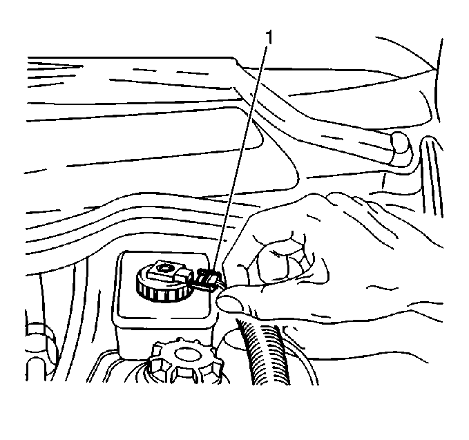
- Disconnect the brake fluid level sensor connection (1) from the reservoir cap.
- Remove the power steering reservoir bracket bolt.
- Remove the power steering reservoir bracket.
- Remove the brake master cylinder.
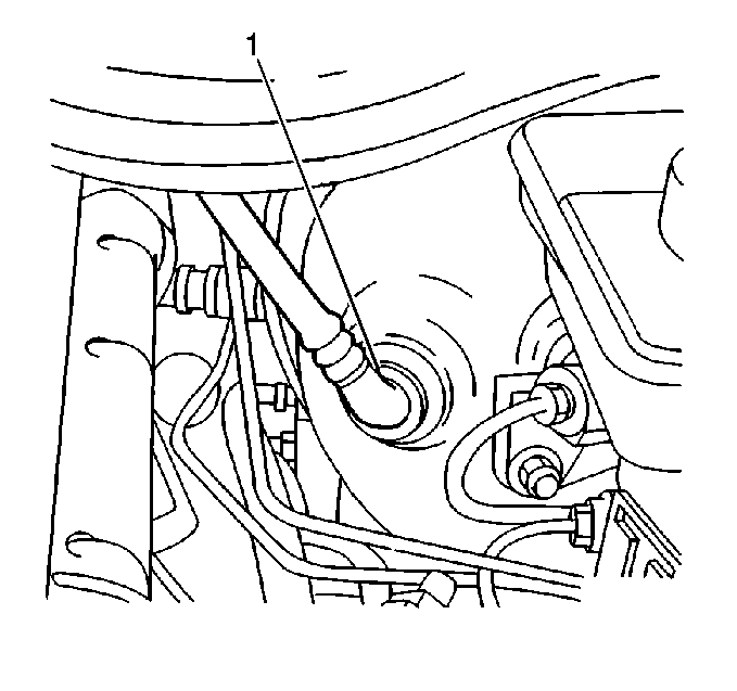
- Remove the power brake booster vacuum hose (1) from the power brake booster.
- Remove the driver side front floor air outlet duct.
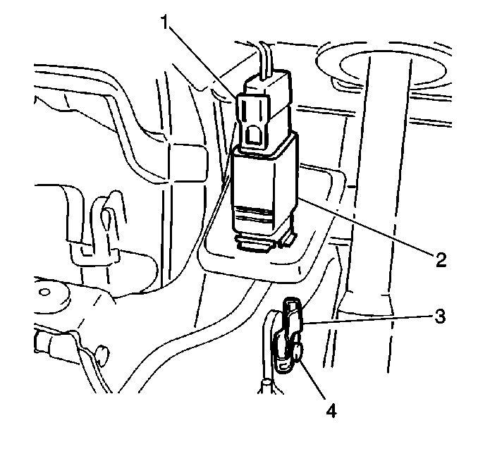
- Remove the brake pedal pivot pin retainer (1) from the brake pedal pivot pin (2).
- Press the brake pedal pivot pin (2) out of the brake master cylinder pushrod clevis.
- Remove the brake master cylinder pushrod clevis from the brake pedal.
- Remove the fuse and relay panel screws.
- Remove the fuse and relay panel. Position the fuse and relay panel out of the way.
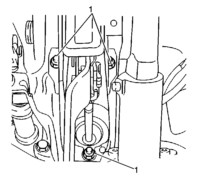
- Remove the brake pedal bracket nuts (1).
- Remove the power brake booster with gasket (to dash) from the bulkhead.
- Remove the power brake booster support bracket washers.
- Remove the power brake booster support bracket nuts.
- Remove the power brake booster support bracket and gasket from the booster.
- Remove the clevis and the power brake booster pushrod nut if replacing the power brake booster.
Important: Ensure not to disturb the clevis adjustment on the pushrod unless replacing the power brake booster.
Installation Procedure
- Install the clevis and install the adjusting nut to the new booster if replacing the power brake booster.
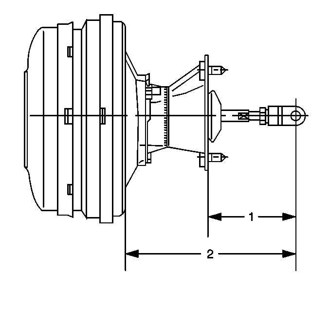
- Adjust the clevis on the pushrod to dimension (1) 105.5 -- 106.5 mm (4.0 -- 4.4 in).
- Tighten the nut.
- Use dimension (2) 179 -- 181 mm (6.7 -- 0.4 in) for an additional check.
- Install the power brake booster gasket to the booster.
- Install the support bracket to the booster.
- Install the support bracket washers to the booster.
- Install the support bracket nuts to the booster.
- Position the power brake booster gasket (to dash) over the studs on the bracket; if removed.
- Install the booster to the bulkhead.
- Install the brake pedal bracket nuts (1).
- Position the fuse and relay panel.
- Install the fuse and relay panel screws.
- Install the brake master cylinder pushrod clevis to the brake pedal.
- Install the brake pedal pivot pin (2) and install the brake pedal pivot pin retainer (1).
- Install the driver side front floor air outlet duct.
- Install the power brake booster vacuum hose (1) to the power brake booster.
- Install the brake master cylinder.
- Connect the brake fluid level sensor connection (1) to the reservoir cap.
- Install the power steering reservoir bracket.
- Install the power steering reservoir bracket bolt.
- Install the A/C evaporator line extension to the cowl. Refer to Evaporator Tube Extension Replacement in HVAC Systems with Automatic AC.
- Install the windshield wiper transmission. Refer to Windshield Wiper Transmission Replacement in Windshield Wiper/Washer System.
- Bleed the brake system. Refer to Hydraulic Brake System Bleeding .
Notice: Use the correct fastener in the correct location. Replacement fasteners must be the correct part number for that application. Fasteners requiring replacement or fasteners requiring the use of thread locking compound or sealant are identified in the service procedure. Do not use paints, lubricants, or corrosion inhibitors on fasteners or fastener joint surfaces unless specified. These coatings affect fastener torque and joint clamping force and may damage the fastener. Use the correct tightening sequence and specifications when installing fasteners in order to avoid damage to parts and systems.
Tighten
Tighten the support bracket nut to 18 N·m (13 lb ft).
Important: Ensure the mounting surface if free of sealant or any other foreign material.

Tighten
Tighten the brake pedal bracket nuts (1) to 20 N·m (15 lb ft).
Tighten
Tighten the fuse and relay panel screws until fully seated. Ensure not
to strip the fuse and relay panel screws.


Tighten
Tighten the power steering reservoir bracket bolt to 7 N·m
(62 lb in).
