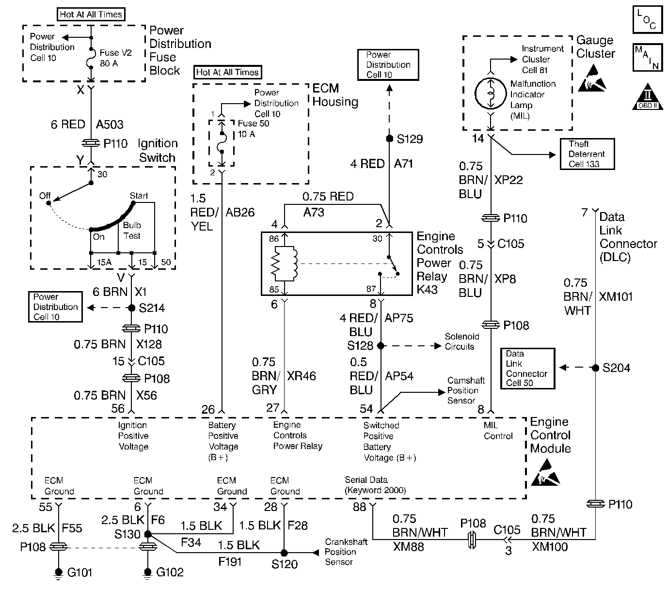
Description
This table assumes that the battery condition and the engine cranking speed are OK. If not, refer to Service Category Engine Electrical for diagnosis. Also, make sure that there is adequate fuel in the tank.
Diagnostic Aids
| • | Use the Connector Test Adapter Kit J 35616 for any test that requires probing the ECM harness connector or a component harness connector. Using this kit will prevent damage to the harness connector terminals |
| • | Unless the engine enters Clear Flood at the first indication of a flooding condition, a no start may result. |
| • | Check the duct work between the Mass Air Flow (MAF) sensor and the throttle body for air leaks. |
| • | A malfunctioning MAF sensor may cause a no start or a stall after start. If this is suspected, disconnect the MAF sensor. The ECM will ignore the MAF sensor and default to calculated air flow. If this corrects the condition and the connections are OK, replace the MAF sensor. |
| • | If the steps above check OK, refer to Service Category Symptoms , Hard Start for diagnosis. |
Test Description
The number(s) below refer to step numbers on the diagnostic table.
-
These DTCs are for systems/components which if operating improperly can cause a no-start.
-
If the vehicle is completely cool (overnight), the ECT and the IAT should be within a few degrees of each other.
-
This engine has a Distributorless Ignition System (DIS). A pair of cylinders share one coil in the following arrangement: 1 and 4, 2 and 5, 3 and 6.
-
Symptoms and Hard Start contains more detailed information on the items listed in this step as well as additional diagnostic aids.
-
Recheck the system for any multiple problems that may be related (for example, fouled spark plugs that were caused by a fuel system problem). Also, some engine mechanical problems could cause the engine to crank but not start.
Step | Action | Value(s) | Yes | No | ||||||
|---|---|---|---|---|---|---|---|---|---|---|
1 | Did you perform the Powertrain On-Board Diagnostic (OBD) System Check? | -- | ||||||||
Check for any DTCs with the scan tool. Are any of the following DTCs displayed: P0100, P0230, P0335, P0560, P0601, P0602, P0604, P1460, P1501, P1502, P1503? | -- | Go to the applicable DTC table | ||||||||
Check the Engine Coolant Temperature with the scan tool. Is the Engine Coolant Temperature on the scan tool close to the actual engine coolant temperature? | -- | Go to DTC P0115 | ||||||||
4 | Check for the TP Normalized with the scan tool. Is the TP Normalized greater than the value specified at closed throttle? | 15% | Go to DTC P0120
| |||||||
Check for a spark while cranking the engine (check at least one wire on each coil) with Spark Tester J 26792 (ST-125). Is the spark present on all of the wires tested? | -- | Go to Ignition System Check | ||||||||
6 |
Was a problem found and corrected? | -- | ||||||||
7 | Probe the Switched B+ circuit in the ECM side of the connector with the test light J 34142-B connected to ground. Does the test light illuminate? | -- | ||||||||
8 |
Does the test light illuminate? | -- | ||||||||
9 | Crank the engine for about 2 seconds, then release the key without turning off the ignition. This procedure should enable the fuel pump. The pump should continue to run for about 2 seconds after the engine stops cranking. Does the fuel pump operate? | -- | Go to Fuel Pump Circuit Diagnosis
| |||||||
10 |
Is the fuel pressure within the range shown? | 275-331 kPa (40-48 psi) | Go to Fuel System Diagnosis | |||||||
Perform the following additional checks:
Was a problem found and corrected? | -- | Go to Hard Start for diagnosis | ||||||||
12 | Repair the open/high resistance Switched B+ circuit to the main injector connector. Is the action complete? | -- | -- | |||||||
13 | Repair the injector harness. Is the action complete? | -- | -- | |||||||
Does the engine start and continue to run? | -- | |||||||||
15 |
Are there any DTCs displayed? | -- | Go to the applicable DTC table | |||||||
16 | Were there any additional DTCs noted during the Powertrain OBD System Check that have not been diagnosed? | -- | Go to the applicable DTC table | The System is OK |
