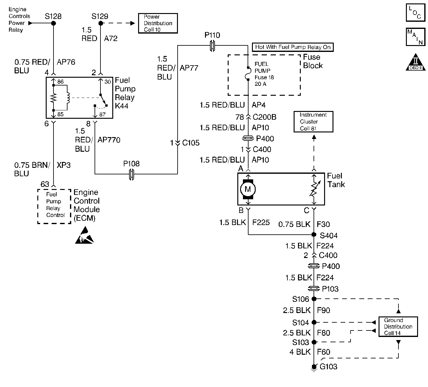
Circuit Description
The Fuel Pump relay coil is supplied power via the Engine Controls Power Relay (switched B+). The Engine Control Module (ECM) controls the relay by grounding the control circuit via an internal solid state device called a driver. When the ECM detects reference pulses from the Crankshaft Position sensor, the ECM will enable the fuel pump. On the switch side of the relay, one of the relay contacts is connected directly to battery positive voltage (B+). The relay controls the power to the Fuel Pump fuse and the fuel pump.
Diagnostic Aids
Use the Connector Test Adapter Kit J 35616 for any test that requires probing the ECM harness connector or a component harness connector. Using this kit will prevent damage to the harness connector terminals.
The following conditions may have caused the fuel pump fuse to open:
| • | The fuse was damaged |
| • | There is an intermittent short in the fuel pump power feed circuit. |
| • | The fuel pump has an intermittent internal problem. |
Step | Action | Value(s) | Yes | No |
|---|---|---|---|---|
1 | Did you perform the Powertrain On-Board Diagnostic (OBD) System Check? | -- | ||
2 | Check the fuel pump fuse. Is the fuse open? | -- | ||
3 |
Does the test light illuminate? | -- | ||
4 |
Does the test light illuminate? | -- | ||
5 |
Does the test light illuminate? | -- | ||
6 |
Is continuity indicated? | -- | ||
7 | Use a fused jumper wire in order to jumper the battery feed circuit to the fuel pump circuit in the fuel pump relay harness connector. The fuel pump should run. Does the fuel pump run? | -- | ||
8 |
Does the test light illuminate? | -- | ||
9 |
Does the test light illuminate? | -- | ||
10 | Probe the ground circuit in the fuel pump harness connector with test light J 34142-B connected to B+. Does the test light illuminate? | -- | ||
11 |
Does the test light illuminate? | -- | ||
12 |
Is the fuse open? | -- | No Trouble Found. Refer to Diagnostic Aids | |
13 | Repair the open battery feed circuit. Is the action complete? | -- | -- | |
14 | Repair the open/high resistance Switched B+ circuit to the Fuel Pump relay. Is the action complete? | -- | -- | |
15 | Repair the open/high resistance relay control circuit. Is the action complete? | -- | -- | |
16 | Repair the open/high resistance fuel pump fuse feed circuit. Is the action complete? | -- | -- | |
17 | Repair the open/high resistance fuel pump feed circuit. Is the action complete? | -- | -- | |
18 | Check for a poor connection or poor harness damage at the fuel pump. Was a problem found and corrected? | -- | ||
19 | Replace the fuel pump. Refer to Service Category Engine Fuel. Is the action complete? | -- | -- | |
20 | Repair the open/high resistance fuel pump ground circuit. Is the action complete? | -- | -- | |
21 | Repair the fuel pump feed circuit shorted to ground. Is the action complete? | -- | -- | |
22 | Check for any poor connections at the relay. Was a problem found and corrected? | -- | ||
23 | Replace the relay. Is the action complete? | -- | -- | |
24 | Check for a poor connections or poor terminal tension at the ECM harness connector. Refer to Electrical Diagnosis in Engine Electrical, Troubleshooting Procedures for the proper procedure. Also, refer to Checking Terminal Contact in Engine Control Module Diagnosis . Was a problem found and corrected? | -- | ||
25 |
Important: This vehicle is equipped with a Theft Deterrent System which interfaces with the Engine Control Module (ECM). Program the new ECM with the frequency code of the theft deterrent module that is currently on the vehicle. Replace the ECM. Refer to Engine Control Module Replacement/Programming . Is the action complete? | -- | -- | |
26 |
Does the engine start and continue to run? | -- | ||
27 |
Are any DTCs displayed? | -- | Go to the applicable DTC table | |
28 | Were there any additional DTCs noted during the Powertrain OBD System Check that have not been diagnosed? | -- | Go to the applicable DTC table | The System is OK |
