Instrument Panel Carrier Replacement Buick
Removal Procedure
After a non-deployment accident, visually inspect the instrument panel carrier for damage or deformation. Any visible damage indicates structural damage and requires replacement of the instrument panel carrier.
- Disconnect the negative battery cable.
- Disable the supplemental inflatable restraint (SIR) system. Refer to Disabling the SIR System in Restraints.
- Remove the right sound insulator. Refer to Instrument Panel Insulator Panel Replacement - Right Side .
- Remove the console. Refer to Console Replacement .
- Remove the instrument cluster trim plate. Refer to Instrument Cluster Trim Panel Replacement .
- Remove the upper trim pad. Refer to Instrument Panel Upper Trim Pad Replacement .
- Remove the knee bolster. Refer to Knee Bolster Replacement .
- Lower the steering column. Refer to Steering Column Replacement in Steering Wheel and Column - Tilt.
- Place a protective cloth on the steering column in order to protect the column from scratches.
- Remove the instrument panel (IP) storage compartment assembly. Refer to Instrument Panel Storage Compartment Replacement .
- Remove the radio and the heater/air conditioning control. Refer to Radio Replacement in Entertainment.
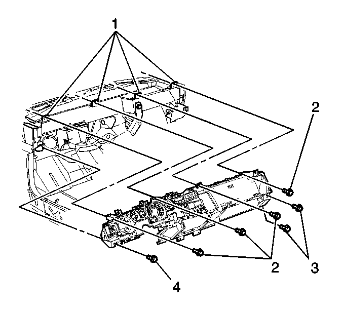
- Remove the fasteners (1) from the left center support bracket.
- Remove the fasteners (2) from the right center support bracket.
- Remove the IP carrier upper to dash panel L-bracket (1) fasteners (2).
- Remove the IP carrier left outer bracket fastener (4).
- Remove the IP carrier to right outer bracket fasteners (3).
- Pull the IP carrier outward and away from the dash.
- Disconnect the electrical connectors.
- Disconnect the antenna coaxial cable.
- Remove the IP carrier.
Caution: Unless directed otherwise, the ignition and start switch must be in the OFF or LOCK position, and all electrical loads must be OFF before servicing any electrical component. Disconnect the negative battery cable to prevent an electrical spark should a tool or equipment come in contact with an exposed electrical terminal. Failure to follow these precautions may result in personal injury and/or damage to the vehicle or its components.
Caution: This vehicle is equipped with a Supplemental Inflatable Restraint (SIR) System. Failure to follow the correct procedure could cause the following conditions:
• Air bag deployment • Personal injury • Unnecessary SIR system repairs • Refer to SIR Component Views in order to determine if you are performing service on or near the SIR components or the SIR wiring. • If you are performing service on or near the SIR components or the SIR wiring, disable the SIR system. Refer to Disabling the SIR System.
Important: Remove the steering column lower mounting bolts prior to removing the upper mounting bolts or damage to the lower steering column bearing may occur.


Installation Procedure
- Install the instrument panel (IP) carrier to the vehicle.
- Connect the electrical connectors.
- Connect the antenna coaxial cable.
- Carefully center the carrier.
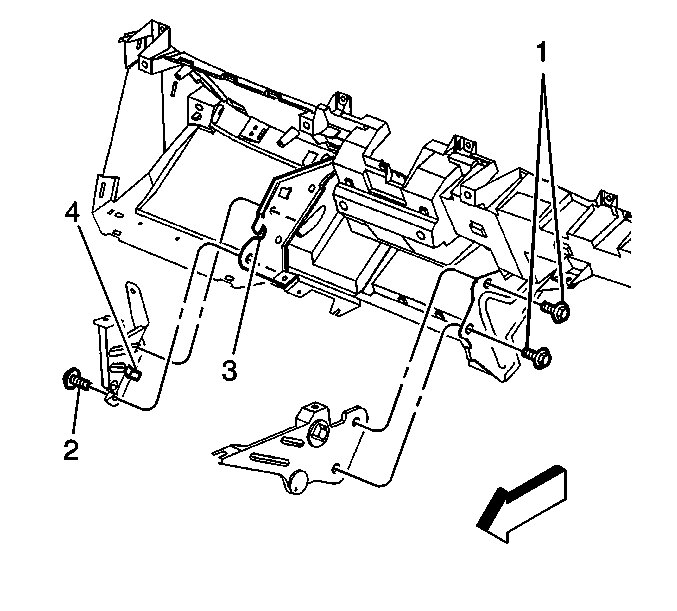
- Engage the right and the left height setting tabs on the backside of the carrier to the slots on the IP outer brackets.
- Engage the height tab (4) of the bracket to the notch (3) in the IP carrier.
- Tug on the lower IP in order to ensure that the tab is locked in place.
- Install the IP carrier to the right outer bracket fasteners (3).
- Install the IP carrier to left outer bracket fastener (4).
- Install the IP carrier upper to the dash panel L-bracket (1) fasteners (2).
- Install the IP carrier to the right center support bracket fasteners (2).
- Install the IP carrier to the left center support bracket fasteners (1).
- Install the radio and the heater/air conditioning control. Refer to Radio Replacement in Entertainment.
- Install the IP storage compartment. Refer to Instrument Panel Storage Compartment Replacement .
- Remove the protective cloth from the steering column.
- Install the steering column. Refer to Steering Column Replacement in Steering Wheel and Column - Tilt.
- Install the knee bolster. Refer to Knee Bolster Replacement .
- Install the upper trim pad. Refer to Instrument Panel Upper Trim Pad Replacement .
- Install the cluster trim plate. Refer to Instrument Cluster Trim Panel Replacement .
- Install the console. Refer to Console Replacement .
- Enable the supplemental inflatable restraint (SIR) system. Refer to Enabling the SIR System in SIR.
- Install the right sound insulator. Refer to Instrument Panel Insulator Panel Replacement - Right Side .
- Connect the negative battery cable.
Assure that the centering feature notch on the IP aligns to the peg on the steering column support bracket.

Push forward and upward on the IP carrier to the lower left of the glove box opening in order to engage the tab (4) of the support bracket to the notch (3) in the IP carrier. An audible click will be heard when engaged.

Notice: Use the correct fastener in the correct location. Replacement fasteners must be the correct part number for that application. Fasteners requiring replacement or fasteners requiring the use of thread locking compound or sealant are identified in the service procedure. Do not use paints, lubricants, or corrosion inhibitors on fasteners or fastener joint surfaces unless specified. These coatings affect fastener torque and joint clamping force and may damage the fastener. Use the correct tightening sequence and specifications when installing fasteners in order to avoid damage to parts and systems.
Tighten
Tighten the fasteners to 9 N·m (80 lb in).
Tighten
Tighten the fastener to 1.9 N·m (17 lb in).
Tighten
Tighten the fasteners to 1.9 N·m (17 lb in).

Tighten
Tighten the fasteners to 10 N·m (89 lb in).
Tighten
Tighten the fasteners to 10 N·m (89 lb in).
Instrument Panel Carrier Replacement Oldsmobile
Removal Procedure
After a non-deployment accident, visually inspect the instrument panel carrier for damage or deformation. Any visible damage indicates structural damage and requires replacement of the instrument panel carrier.
- Disconnect the negative battery cable.
- Disable the supplemental inflatable restraint (SIR) system. Refer to Disabling the SIR System in SIR.
- Remove the right sound insulator. Refer to Instrument Panel Insulator Panel Replacement - Right Side .
- Remove the console. Refer to Console Replacement .
- Remove the instrument cluster trim plate. Refer to Instrument Cluster Trim Panel Replacement .
- Remove the windshield garnish moldings. Refer to Windshield Pillar Garnish Molding Replacement in Interior Trim.
- Remove the upper trim pad. Refer to Instrument Panel Upper Trim Pad Replacement .
- Remove the knee bolster reinforcement. Refer to Knee Bolster Replacement .
- Remove the instrument panel storage compartment assembly. Refer to Instrument Panel Storage Compartment Replacement .
- Lower the steering column. Refer to Steering Column Replacement in Steering Wheel and Column - Tilt.
- Place a protective cloth on the steering column in order to protect the column from scratches.
- Remove the radio. Refer to Radio Replacement in Entertainment.
- Remove the Heater and A/C control. Refer to Control Assembly Replacement in HVAC Systems-Automatic.
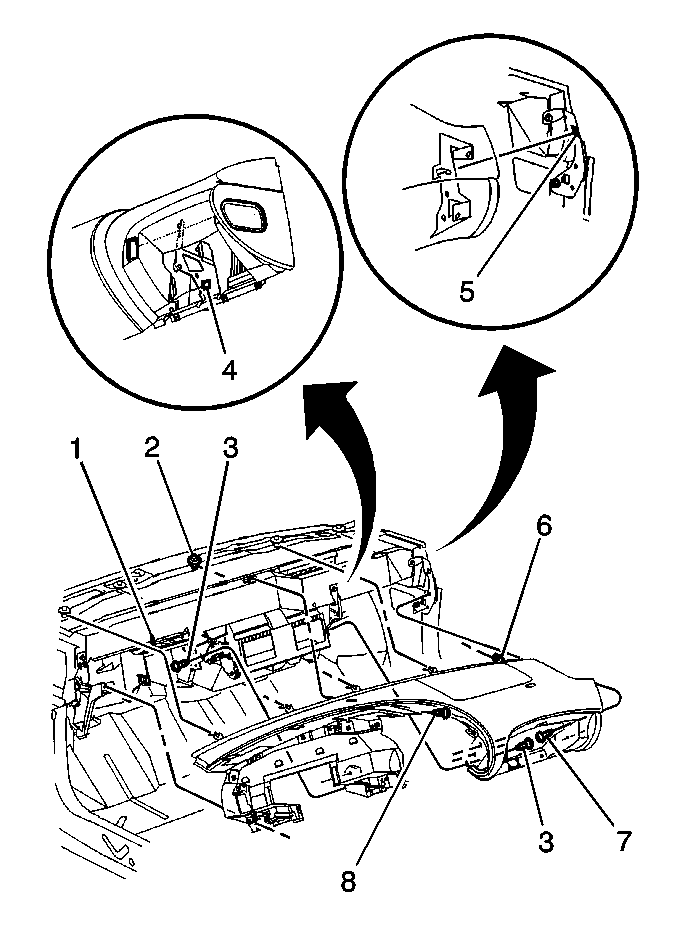
- Remove the fasteners (3,7,8).
- Pull the instrument panel carrier away from the dash.
- Disconnect the electrical connectors.
- Disconnect the antenna coaxial cable.
- Remove the instrument panel carrier.
Caution: Unless directed otherwise, the ignition and start switch must be in the OFF or LOCK position, and all electrical loads must be OFF before servicing any electrical component. Disconnect the negative battery cable to prevent an electrical spark should a tool or equipment come in contact with an exposed electrical terminal. Failure to follow these precautions may result in personal injury and/or damage to the vehicle or its components.
Caution: This vehicle is equipped with a Supplemental Inflatable Restraint (SIR) System. Failure to follow the correct procedure could cause the following conditions:
• Air bag deployment • Personal injury • Unnecessary SIR system repairs • Refer to SIR Component Views in order to determine if you are performing service on or near the SIR components or the SIR wiring. • If you are performing service on or near the SIR components or the SIR wiring, disable the SIR system. Refer to Disabling the SIR System.
Important: Remove the steering column lower mounting bolts prior to removing the upper mounting bolts or damage to the lower steering column bearing may occur.

Installation Procedure
- Install the instrument panel (IP) carrier.
- Connect the electrical connectors.
- Connect the antenna coaxial cable.
- Carefully align the carrier.
- Locate the IP to the height pin (5) on the IP outer bracket.
- Engage the height tab (4) on the right center mounting bracket to the notch in the IP carrier.
- Ensure that the tab is locked in place by tugging on the lower IP.
- Install the IP carrier to the upper L-bracket fastener (8).
- Install the center support bracket fasteners (3).
- Install the outer bracket fasteners (7).
- Install the Heater and A/C control. Refer to Control Assembly Replacement in HVAC Systems-Automatic.
- Install the radio. Refer to Radio Replacement in Entertainment.
- Remove the protective cloth from the steering column.
- Install the steering column. Refer to Steering Column Replacement in Steering Wheel and Column - Tilt.
- Install the instrument panel storage compartment. Refer to Instrument Panel Storage Compartment Replacement .
- Install the knee bolster reinforcement. Refer to Knee Bolster Replacement .
- Install the upper trim pad. Refer to Instrument Panel Upper Trim Pad Replacement .
- Install the windshield garnish moldings. Refer to Windshield Pillar Garnish Molding Replacement in Interior Trim.
- Install the cluster trim plate. Refer to Instrument Cluster Trim Panel Replacement .
- Install the console. Refer to Console Replacement .
- Enable the supplemental inflatable restraint (SIR) system. Refer to Enabling the SIR System in SIR.
- Install the right sound insulator. Refer to Instrument Panel Insulator Panel Replacement - Right Side .
- Connect the negative battery cable.

Ensure that the 5 cowl clips (6) are secured under the mushroom header (2). Ensure that the studs on the cowl and the centering feature on the IP aligns to the peg (1) on the steering column support bracket.
Push forward and upward on the IP carrier to the lower left of the glove box opening in order to engage the tab of the support bracket to the notch in the IP carrier bracket. An audible click will be heard when engaged.
Notice: Use the correct fastener in the correct location. Replacement fasteners must be the correct part number for that application. Fasteners requiring replacement or fasteners requiring the use of thread locking compound or sealant are identified in the service procedure. Do not use paints, lubricants, or corrosion inhibitors on fasteners or fastener joint surfaces unless specified. These coatings affect fastener torque and joint clamping force and may damage the fastener. Use the correct tightening sequence and specifications when installing fasteners in order to avoid damage to parts and systems.
Tighten
Tighten the fastener to 1.9 N·m (17 lb in).
Tighten
Tighten the fasteners to 10 N·m (89 lb in).
Tighten
Tighten the fasteners to 10 N·m (89 lb in).
