Second Coast Brake Removal
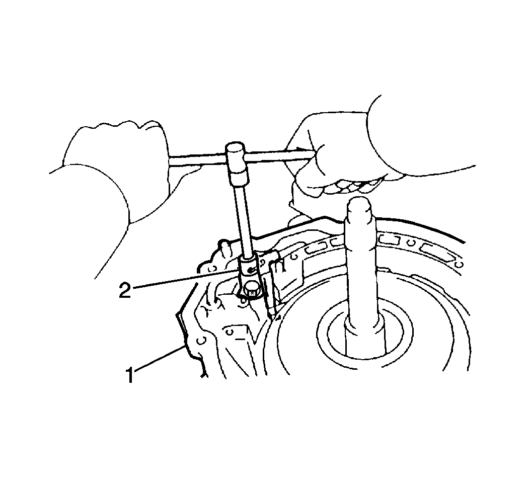
- Remove the 1 bolt and the second coast brake apply pipe bracket (2) from the transaxle case (1).
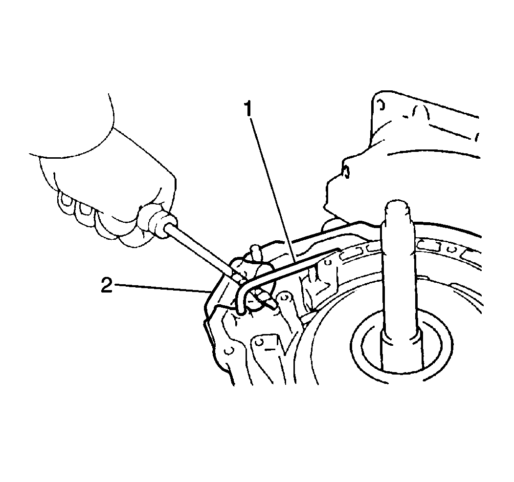
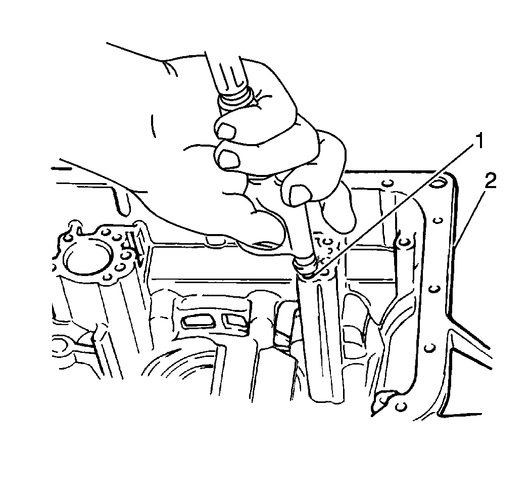
- Remove the 2nd coast brake apply pipe (1) from the transaxle case (2).
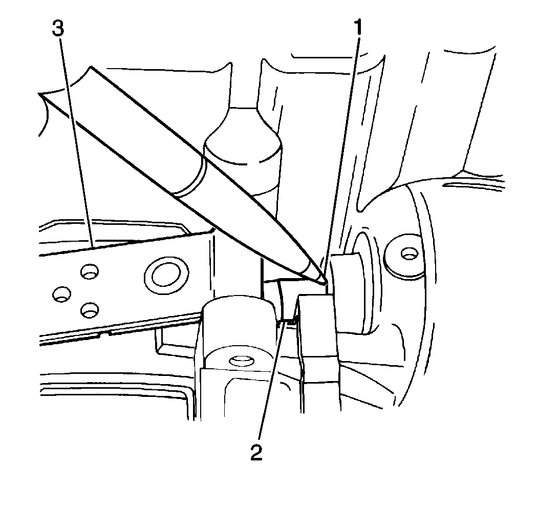
- Place a reference mark (1) on the 2nd coast brake piston rod (2) where the piston rod meets the
transaxle case.
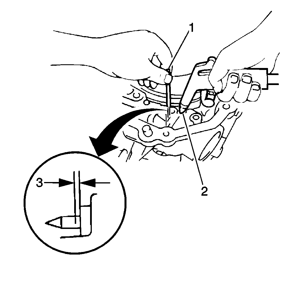
- Apply 392-785 kPa (57-114 psi) of compressed air into the 2nd coast brake apply passage (2).
- Measure the distance between the reference mark and the transaxle case using a feeler gage (1) to obtain the 2nd coast brake piston stroke.
| • | The 2nd coast brake piston stroke should fall within 1.5-3.5 mm (0.059-0.138 in) (3). |
| • | If the 2nd coast brake piston stroke exceeds specification, inspect the 2nd coast brake band for excessive wear or damage. |
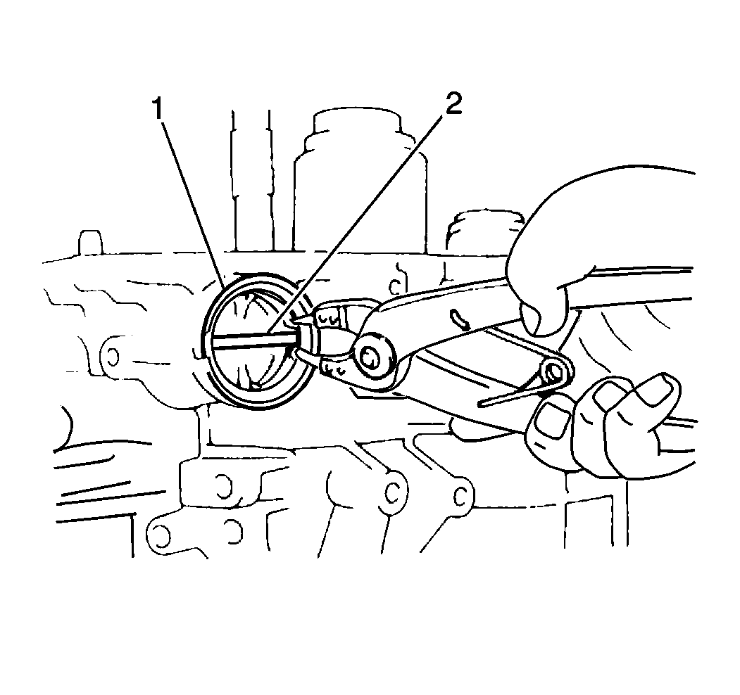
- Remove the 2nd coast brake servo cover snap ring (1) from the transaxle case.
Important: When using compressed air to remove components, air pressure should not exceed 98 kPa (14 psi).
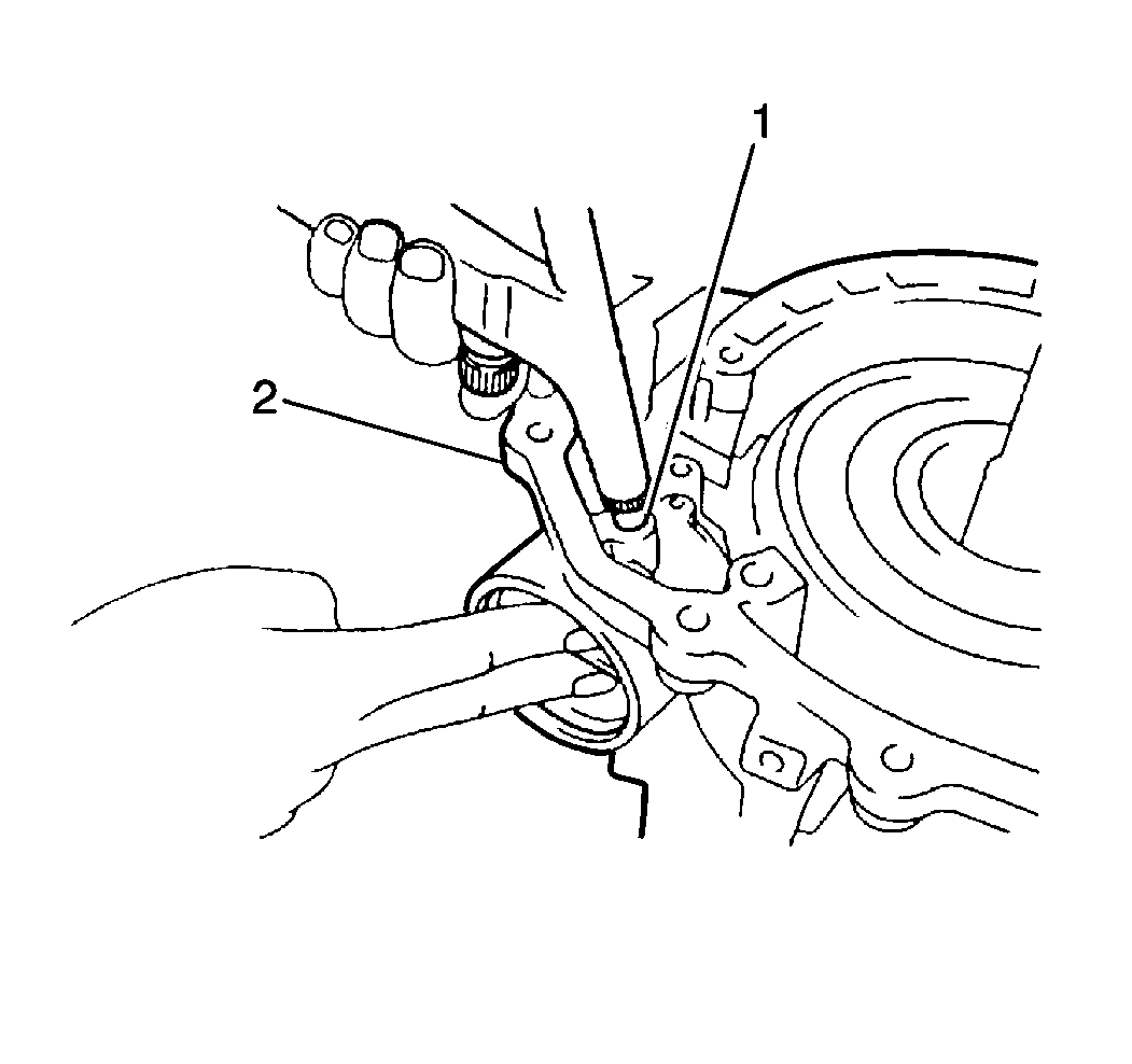
- Remove the following components from the
transaxle case (2) by slowly applying low pressure compressed air into the 2nd coast brake servo apply passage (1):
| • | The 2nd coast brake servo cover |
| • | The 2nd coast brake piston |
| • | The 2nd coast brake piston outer return spring |
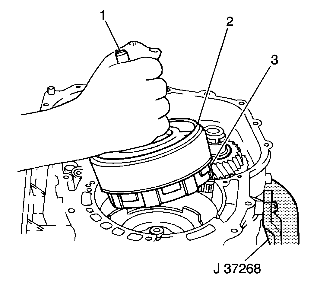
- Remove the forward and direct clutch assemblies (3, 2) from the transaxle case by grasping the input
shaft (1) and lifting the shaft upward.
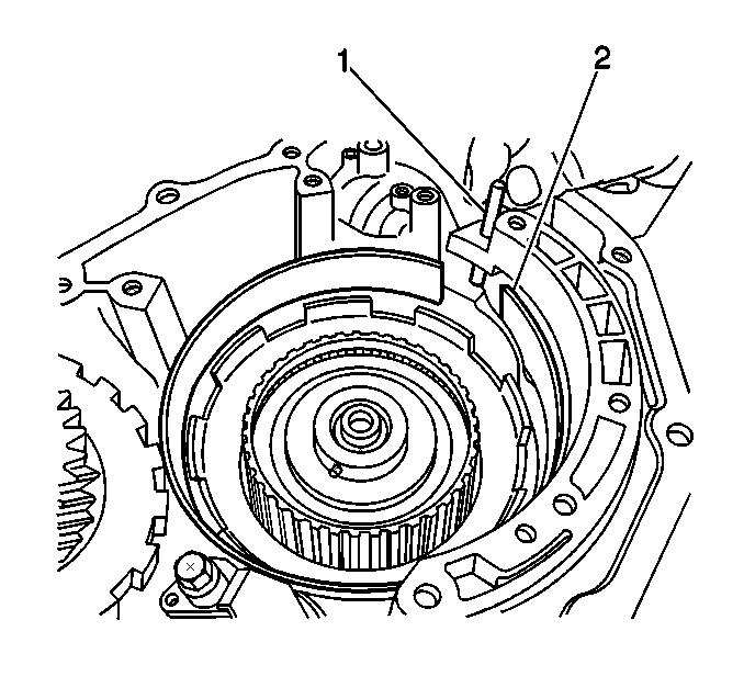
- Remove the 2nd coast brake band anchor pin (2) from the transaxle case (1).
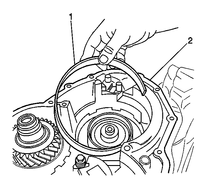
- Remove the 2nd coast brake band from the transaxle case (1).
First Reverse Brake Removal
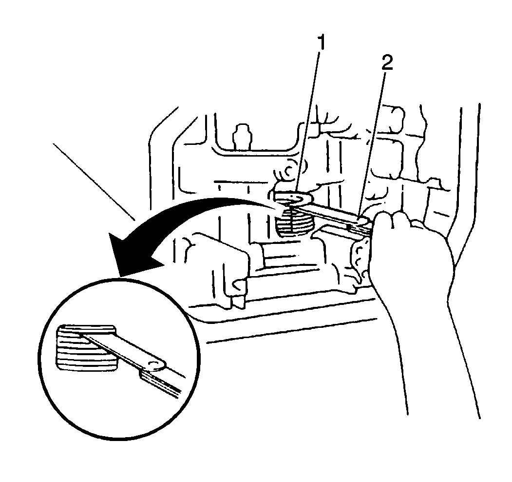
- Measure the 1st-reverse brake assembly clearance (1) using a feeler gage (2).
| • | The 1st-reverse brake assembly clearance should fall within 1.060-2.380 mm (0.0417-0.0937 in). |
| • | If the 1st-reverse brake assembly clearance is below 1.060 mm (0.0417 in), inspect the 1st-reverse brake assembly components for excessive wear or damage. |
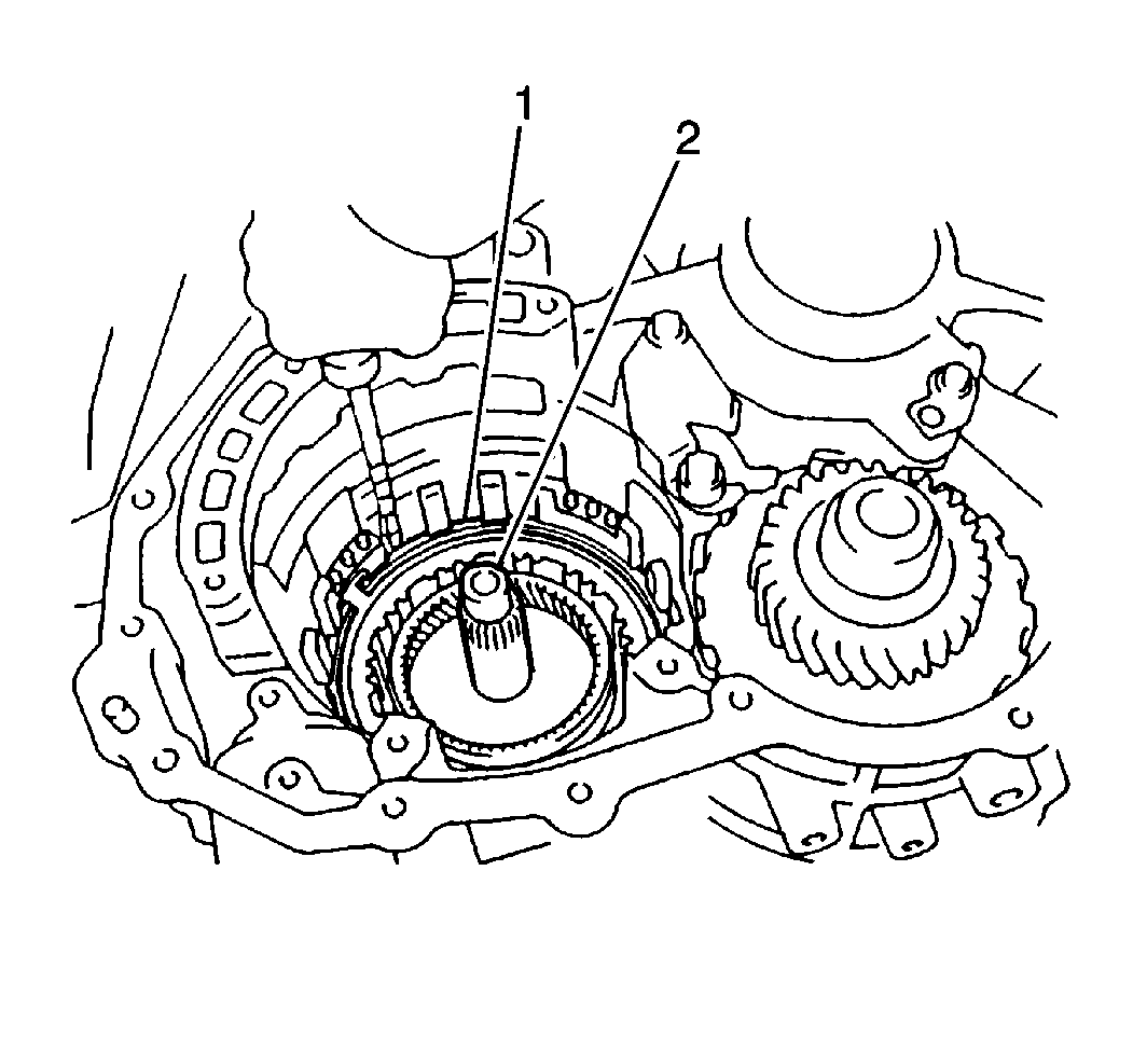
- Remove the 1st-reverse brake snap ring (1) from the transaxle case.
- Remove the following components from the transaxle case:
| • | 1st-reverse brake flange |
First Reverse Brake Piston Removal
Tools Required
| • | J 35683
First and Reverse Brake Piston Compressor |
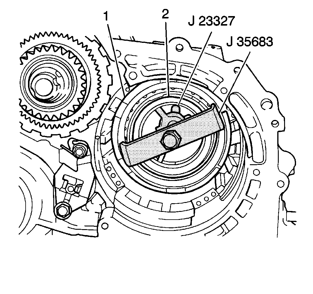
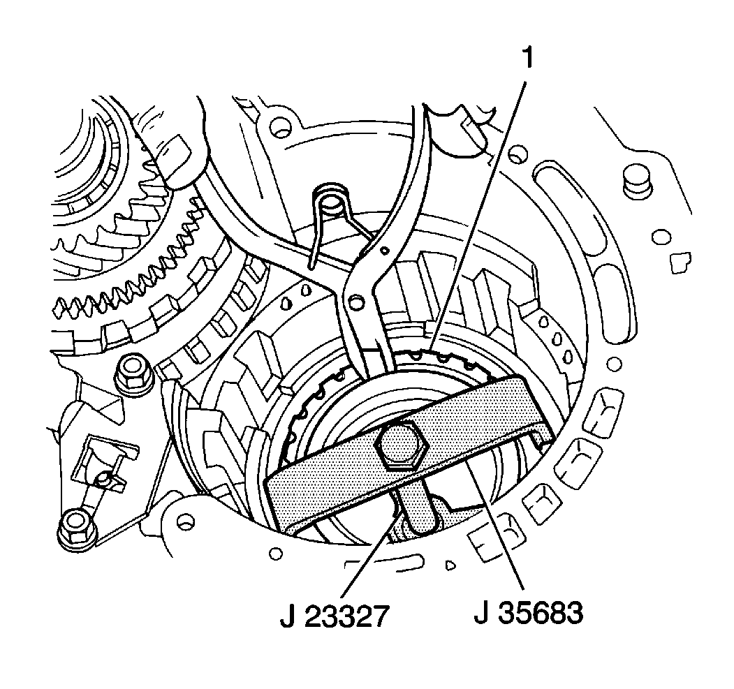
- Install the
J 23327
with a
J 35683
and compress the 1st-reverse brake piston return spring until the 1st-reverse brake piston return spring snap ring (2) can be removed.
- Remove the 1st-reverse brake piston return spring snap ring (1) from the
transaxle case.
- Remove the
J 23327
and the
J 35683
from the transaxle case.
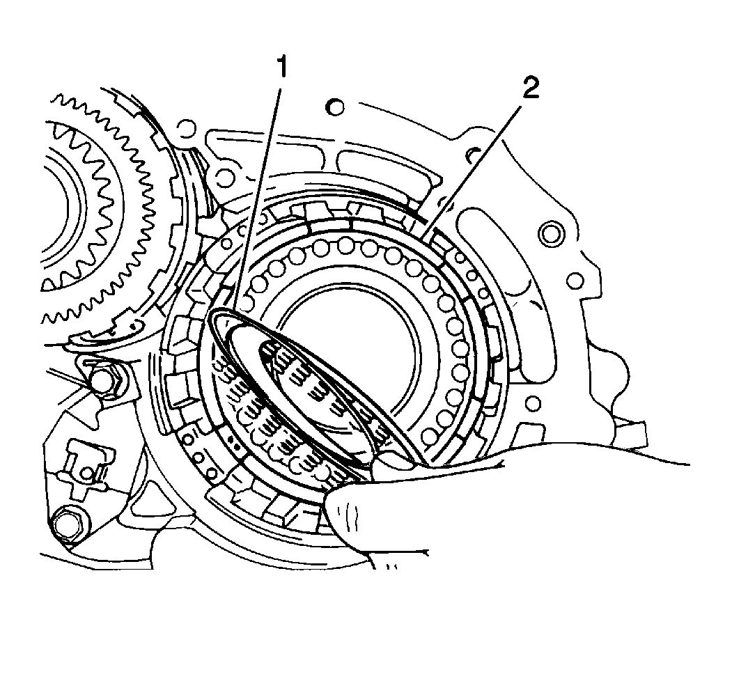
- Remove the 1st-reverse brake piston return spring (1) from the transaxle case.
Caution: Wear safety glasses in order to avoid eye damage.
Important: When using compressed air to remove components, air pressure should not exceed 98 kPa (14 psi).
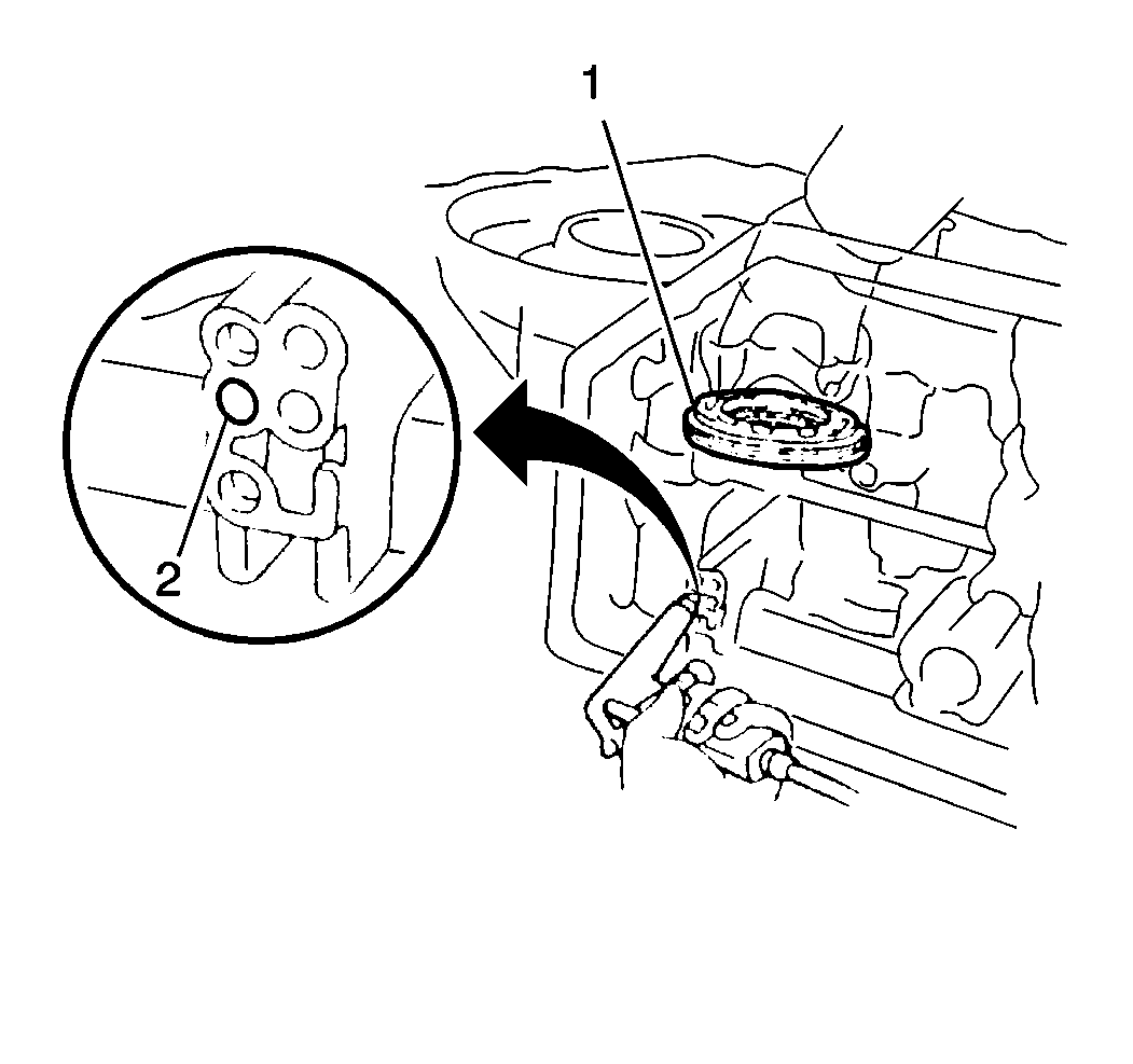
- Remove the 1st-reverse brake piston (1) from the transaxle case by slowly applying low pressure compressed air into the fluid
passage (2).
- Remove the 1st-reverse brake assembly.
Underdrive Clutch Removal
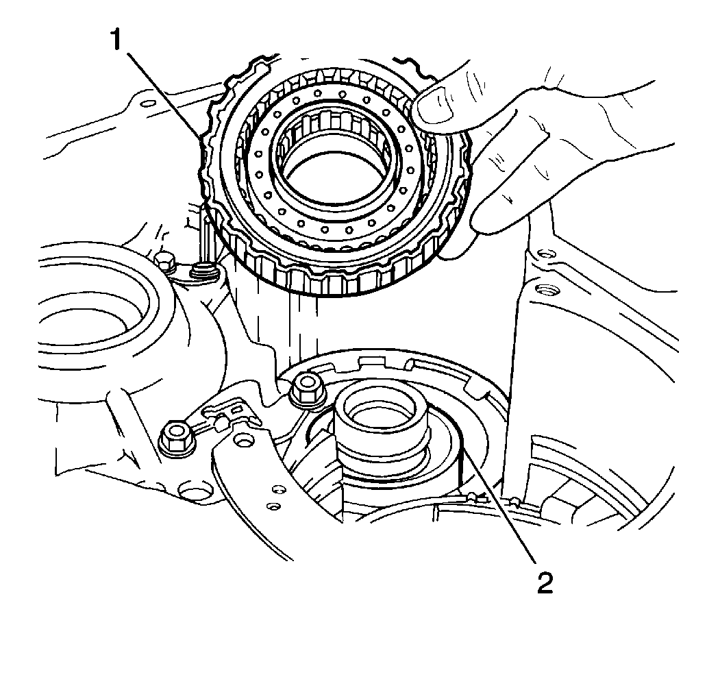
- Remove the underdrive clutch assembly (1) from the underdrive one-way clutch and the underdrive brake assembly (2).
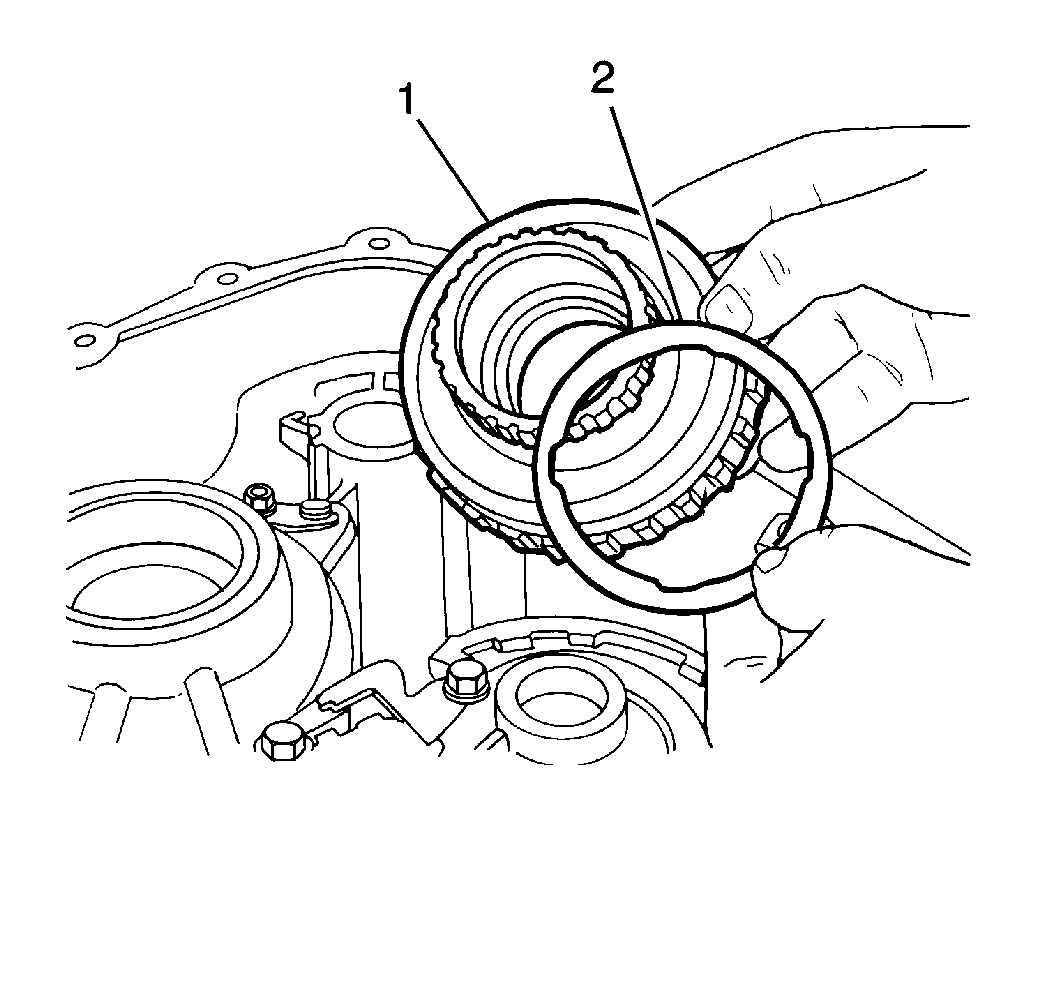
- Remove the underdrive clutch thrust washer (2) from the rear of the underdrive clutch drum (1).
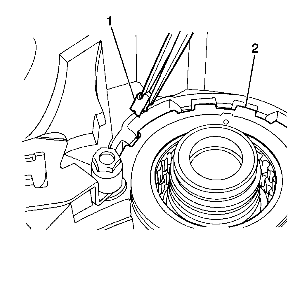
- Remove the underdrive one-way clutch anti-rattle clip (1) from the transaxle
case.
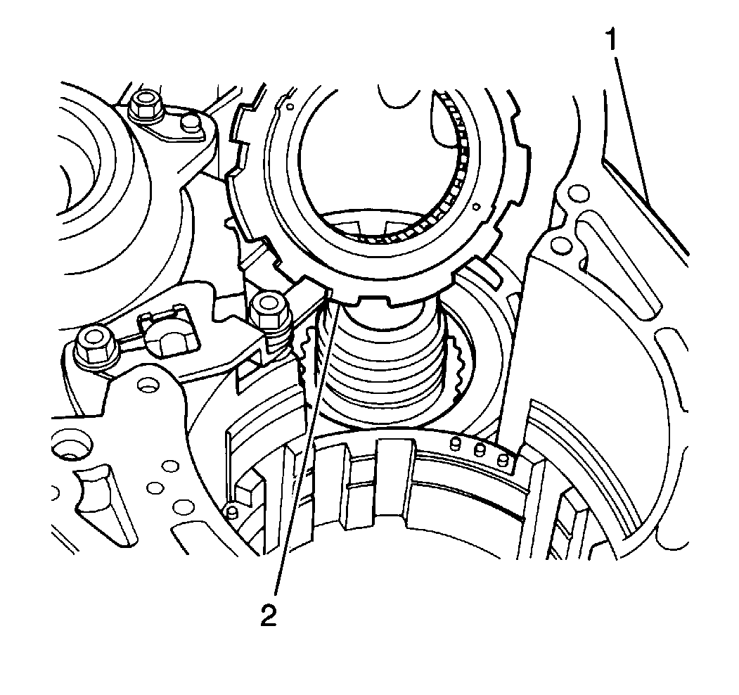
- Remove the underdrive one-way clutch (2) from the transaxle case (1).
Underdrive Brake Removal
Tools Required
| • | J 7872
Magnetic Base Indicator Set |
| • | J 37282
Underdrive Brake Piston Compressor |
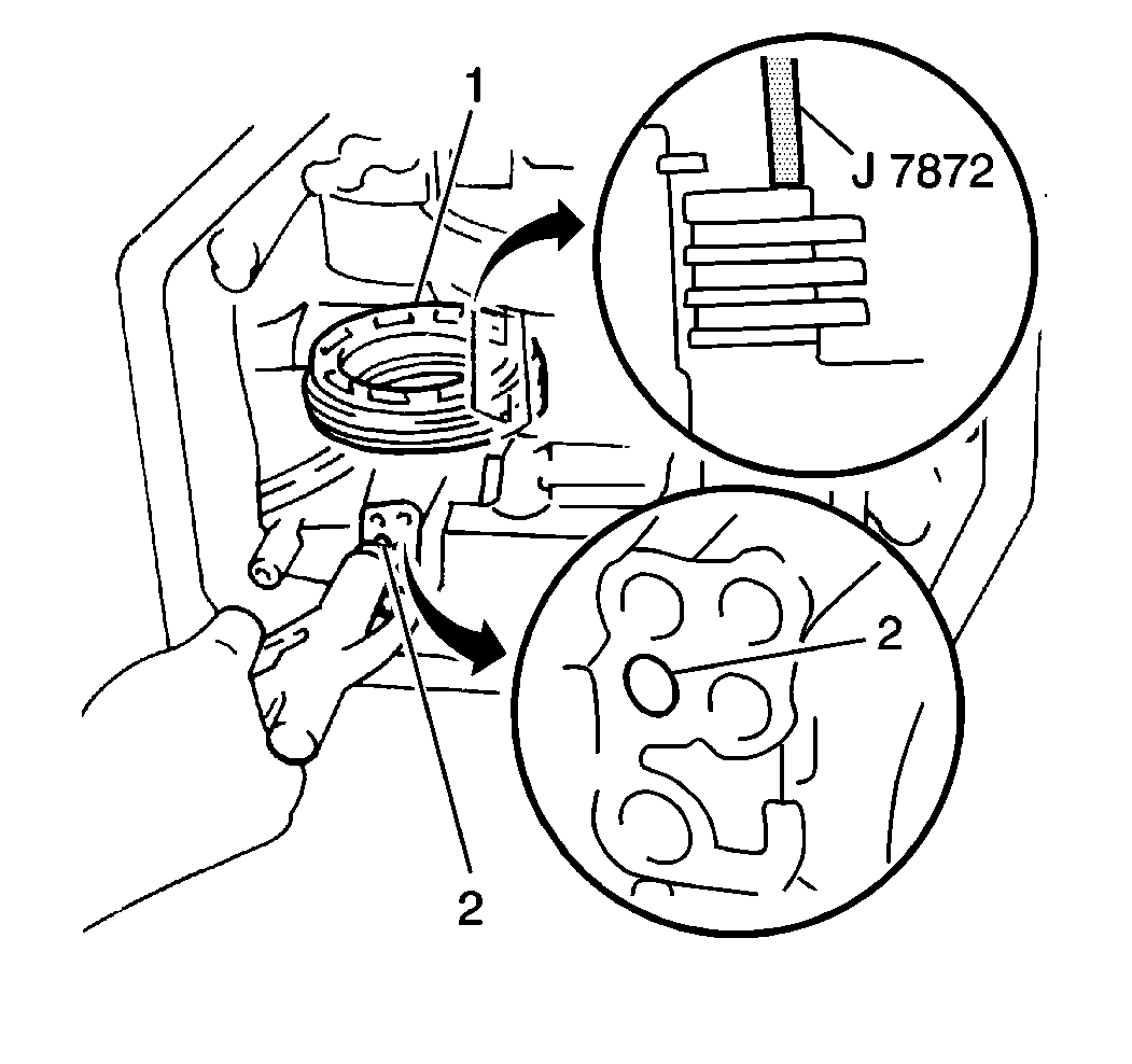
- Use the
J 7872
in order to measure the underdrive brake
assembly (1) clearance.
- Apply 392-785 kPa (57-114 psi) of compressed air into the underdrive brake apply passage (2). Measure the underdrive brake assembly clearance.
- The underdrive brake assembly clearance should fall within 1.070-2.050 mm (0.0421-0.0807 in).
- If the underdrive brake assembly clearance does not fall within specification, inspect the underdrive brake assembly components for excessive wear or damage.
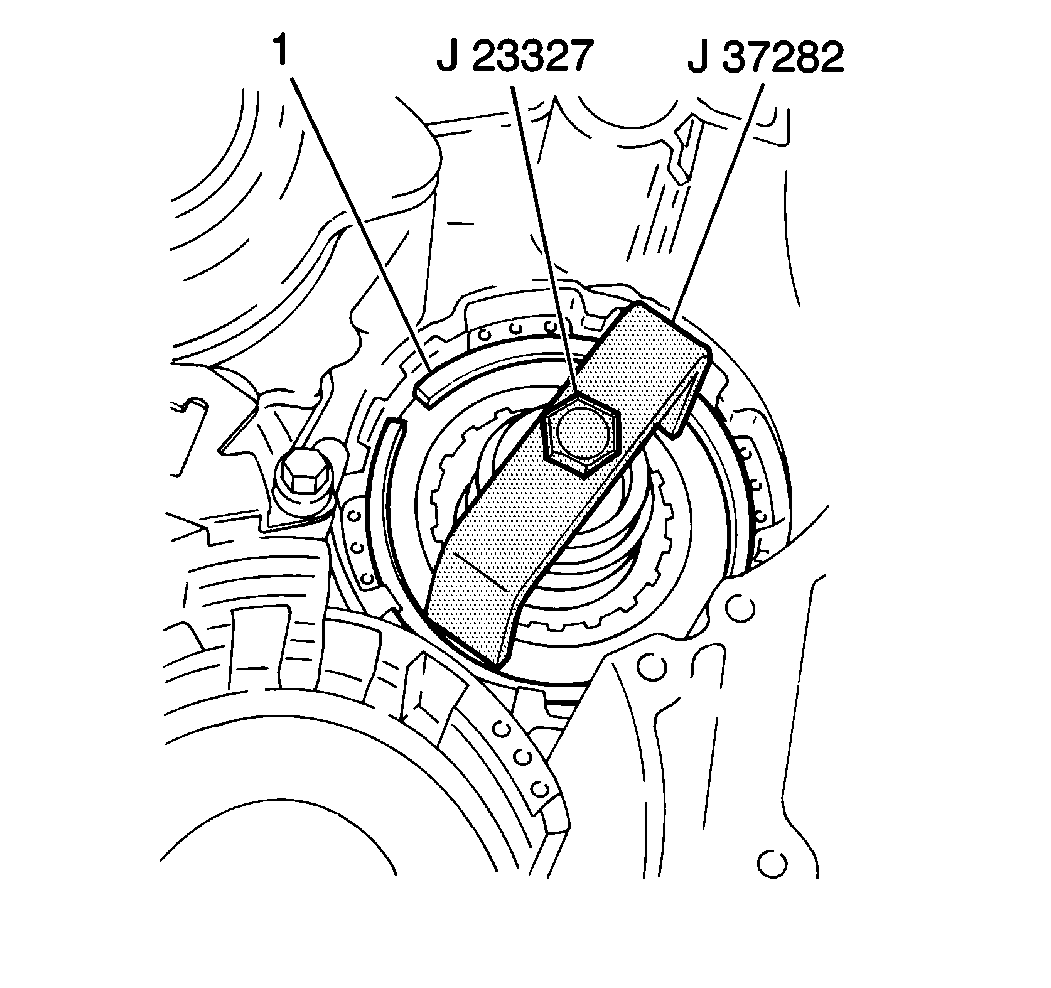
- Install a
J 23327
with a
J 37282
and compress the underdrive brake piston return spring until the underdrive brake piston return spring snap ring (1) can be removed.
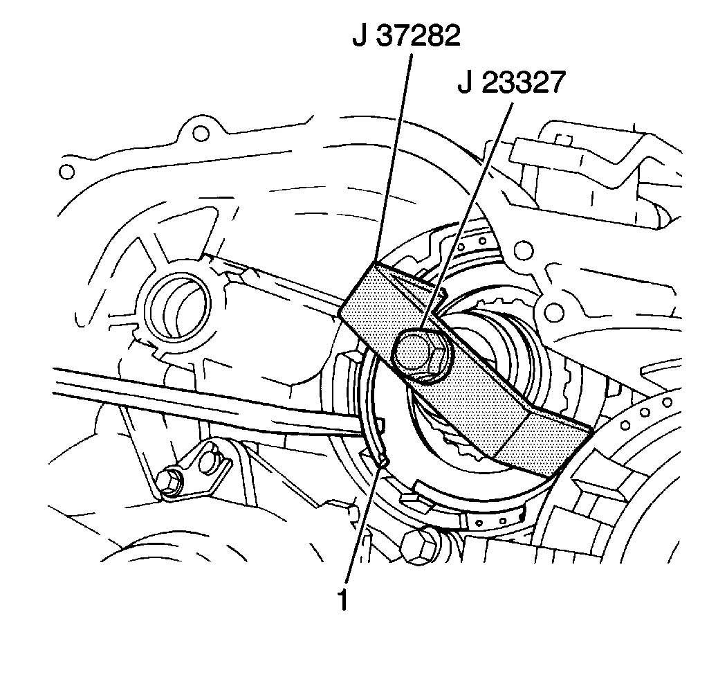
- Remove the underdrive brake piston return spring snap ring (1) from the
transaxle case.
- Remove the
J 23327
and the
J 37282
from the transaxle case.
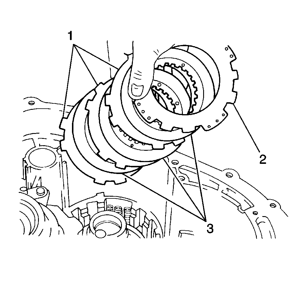
- Remove the underdrive brake flange (2), the three plates (1) and
the three discs (3) from the transaxle case.
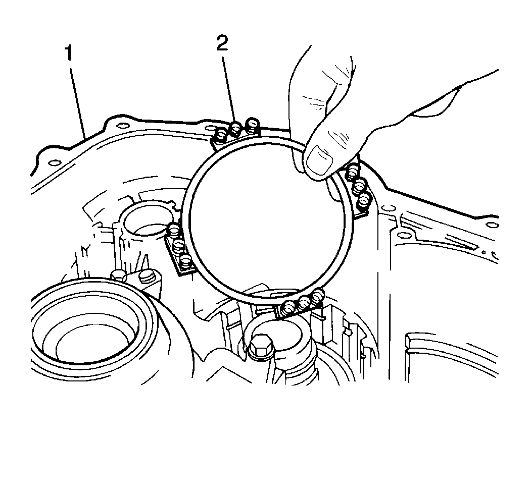
- Remove the underdrive brake piston return spring (2) from the transaxle case (1).
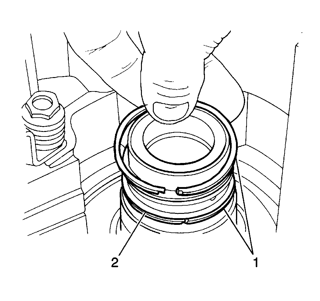
- Remove the two seal rings (1) from the underdrive clutch drum support (2).
Caution: Wear safety glasses in order to avoid eye damage.
Important: When using compressed air to remove components, air pressure should not exceed 98 kPa (14 psi).

- Remove the underdrive brake piston from the transaxle case by slowly applying low pressure compressed air into
the underdrive brake apply passage (2).
Torque Converter Housing Removal
Tools Required
| • | J 26941
Countershaft Bearing and Drive Axle Seal Remover |
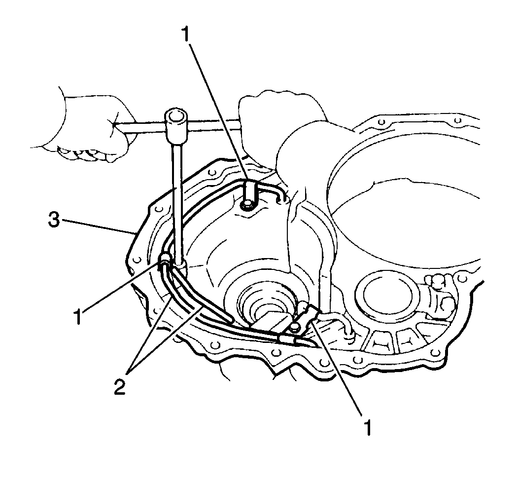
- Remove the 3 bolts and the 3 fluid pipe clamps (1) from the torque converter housing (3).
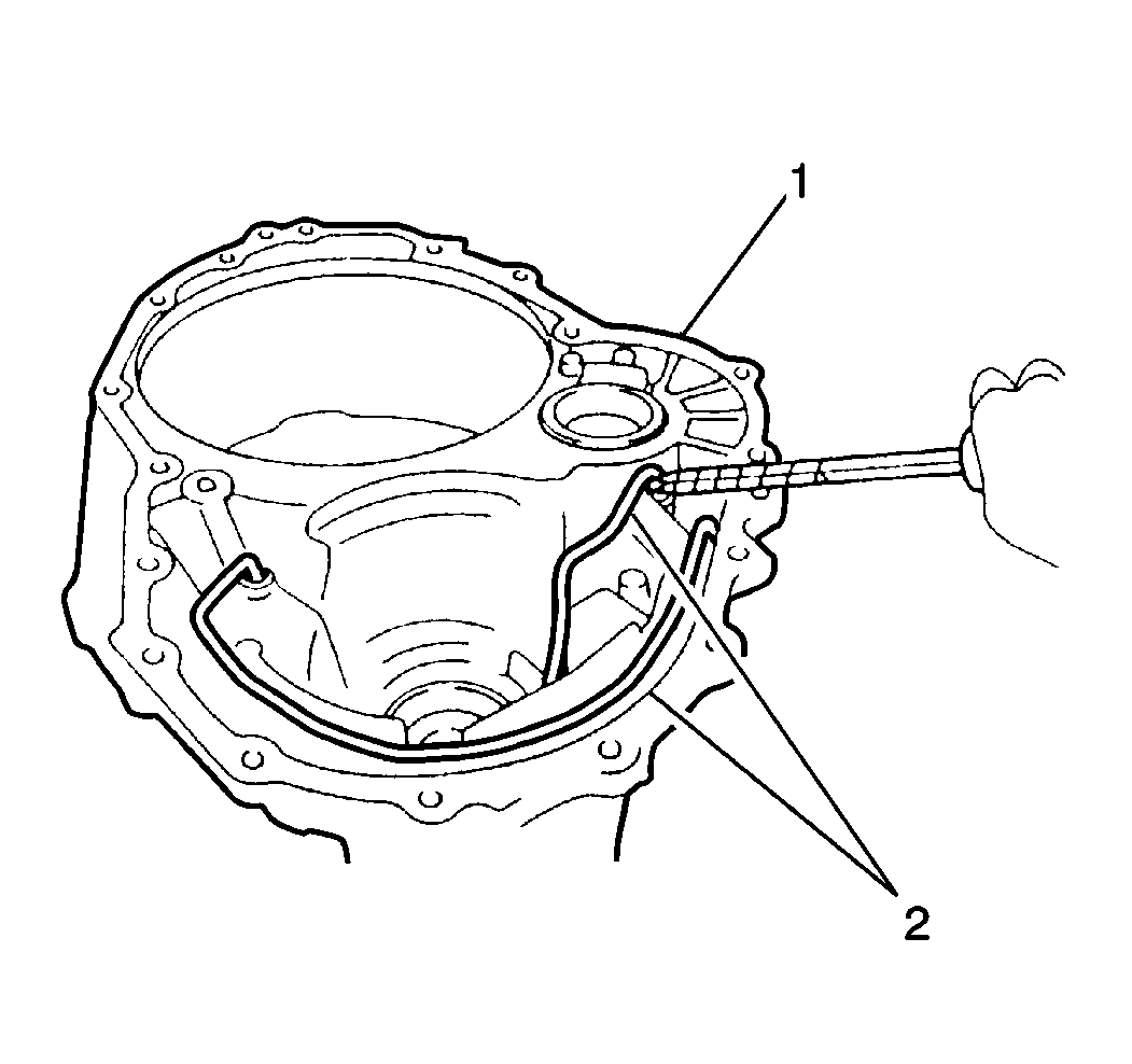
- Remove the 2 fluid pipes (2) from the torque converter housing (1).
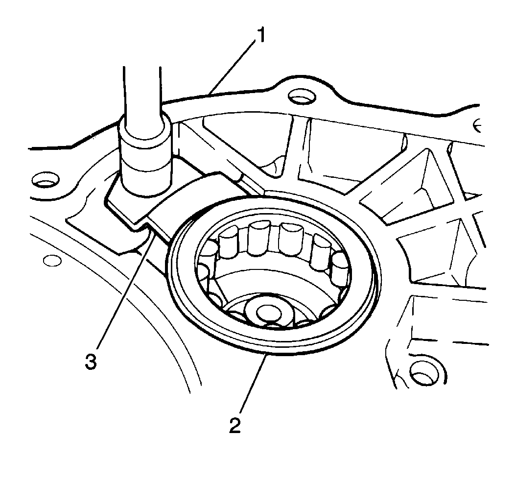
- Remove the bolt and the countershaft front roller bearing retainer (3) from
the torque converter housing (1).
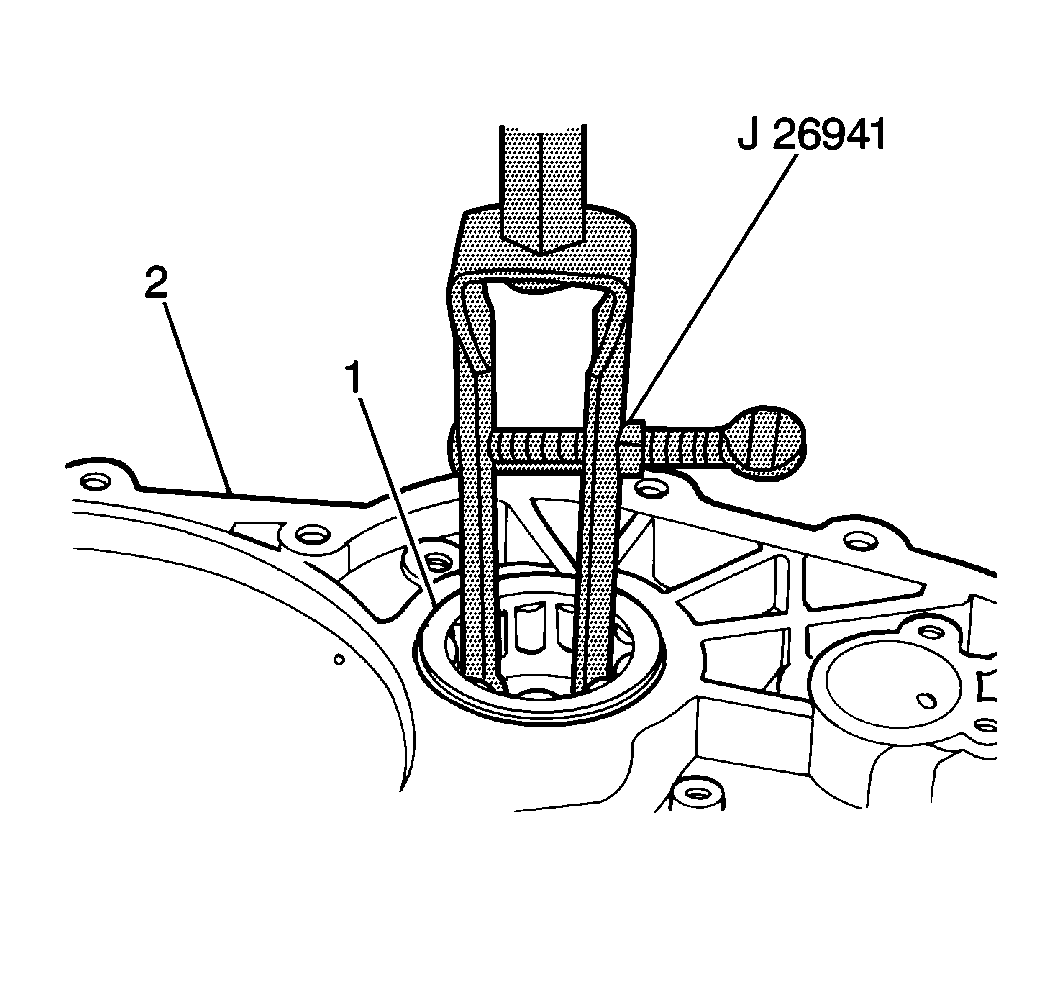
- Use the
J 26941
with a
J 2619-01
in order to remove the countershaft front roller bearing (1) from the torque converter housing (2).
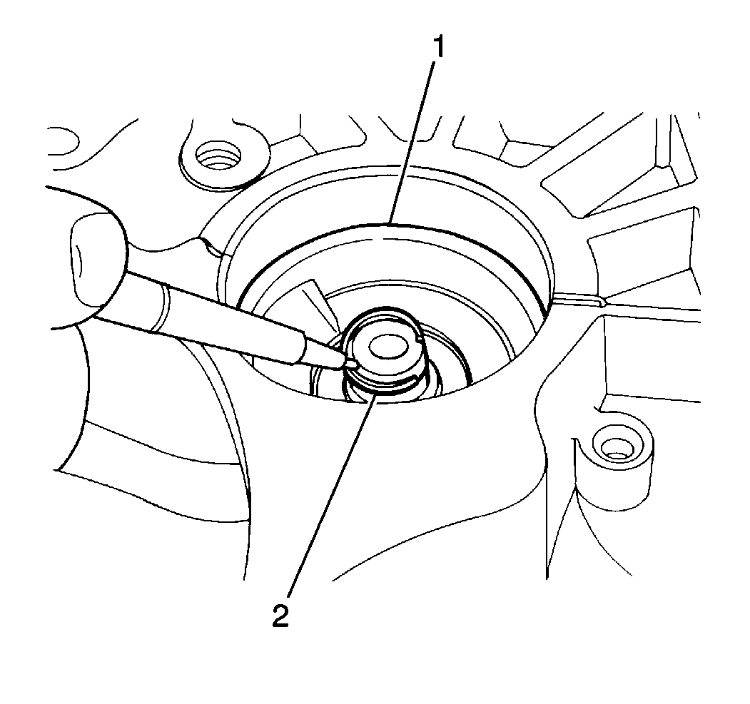
- Remove the countershaft lubrication seal (2) from the countershaft front roller bearing bore (1).
- Use the
J 26941
with a
J 2619-01
in order to remove the right drive axle shaft fluid seal from the torque converter housing.
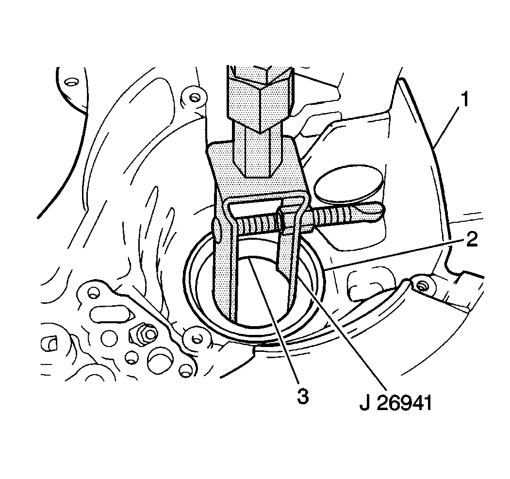
- Use the
J 26941
with a
J 2619-01
in order to remove the following components from the torque converter housing (1):
| • | The right differential side bearing race (2) |
| • | The right differential selective shim (3) |
- Clean the sealant from the torque converter housing-to-transaxle case mating surfaces.
Case Assembly Cleaning
- Thoroughly clean the case components with solvent.
- Air dry the components.
- DO NOT wipe the components with cloths or rags.
Second Coast Brake Replacement
Tools Required
J 26900-6
Dial Caliper
Removal Procedure
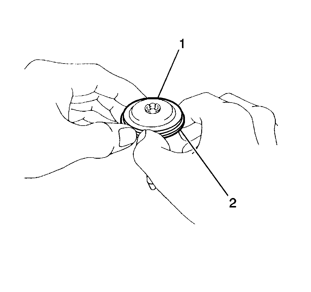
- Remove the two 2nd coast brake servo cover seals from the 2nd coast brake servo cover.
- Remove the seal (2) from the 2nd coast brake piston (1).
- Remove the following components from the 2nd coast brake piston:
| • | The 2nd coast brake piston rod |
| • | The 2nd coast brake piston rod E-ring |
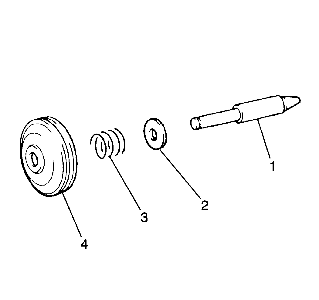
- Remove the following components from the 2nd coast brake piston rod (1):
| • | The 2nd coast brake inner return spring (3) |
| • | The 2nd coast inner return spring seat (2) |
- Clean all of the 2nd coast brake components and dry the components thoroughly.
- Inspect the following components for cracks or porosity. Replace the components as necessary:
| • | The 2nd coast brake servo cover |
| • | The 2nd coast brake piston (4) |
- Inspect the following components for distortion or excessive wear. Replace the components as necessary:
| • | The 2nd coast brake inner return spring |
| • | The 2nd coast brake outer return spring |
- Inspect the 2nd coast brake band lining for cracks or excessive wear and replace as necessary. If the 2nd coast brake piston stroke is not within specification, measure the 2nd coast brake piston rod length to determine a suitable replacement 2nd
coast brake piston rod.
- Use the
J 26900-6
in order to measure the 2nd coast brake piston rod length.
- If the 2nd coast brake band appears to exhibit little or no wear, select one of the two different size piston rod lengths available in order to lengthen or shorten the 2nd coast brake piston rod stroke until the stroke is within specification.
There are two 2nd coast brake piston rod lengths available:
Installation Procedure

- Install the following components onto the 2nd coast brake piston rod (1):
| • | The 2nd coast brake inner return spring seat (2) |
| • | The 2nd coast brake inner return spring (3) |
- Install the 2nd coast brake servo piston rod into the 2nd coast brake piston (4). Secure the servo piston rod with one E-ring.
- Install the new 2nd coast brake piston seal onto the 2nd coast brake piston.
- Install the 2 new 2nd coast brake servo cover seals onto the 2nd coast brake servo cover.
Intermediate One-Way Clutch Replacement
Tools Required
J 26900-6
Dial Caliper
Removal Procedure
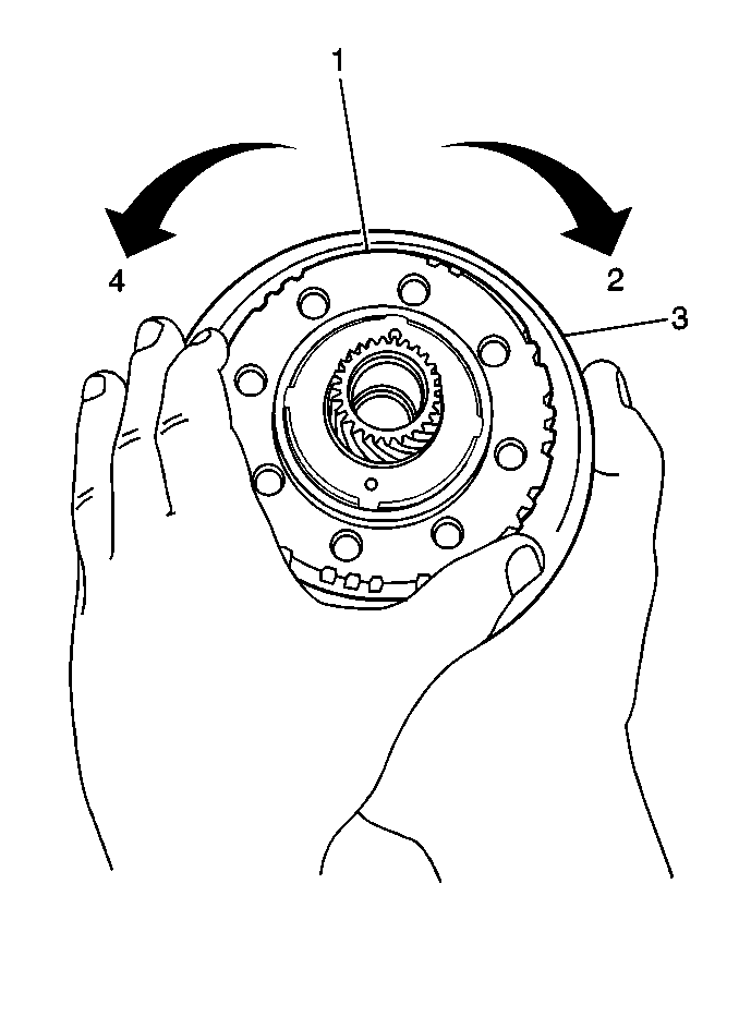
- Inspect the intermediate one-way clutch before disassembly by placing the intermediate brake hub and the intermediate
one-way clutch onto the rear of the sun gear input drum, holding the sun gear input drum stationary and rotating the intermediate brake hub.
| • | The intermediate brake hub should turn freely in a clockwise direction (2) and should not turn in a counterclockwise direction (4). |
| • | If the intermediate brake hub is installed correctly on the sun gear input drum and the intermediate brake hub can be turned counterclockwise, replace the intermediate brake hub and intermediate one-way clutch |
Notice: The intermediate one-way clutch should be disassembled for inspection
purposes only. If excessive wear or damage is found in any component of the
intermediate one-way clutch upon inspection, replace the intermediate brake
hub assembly.
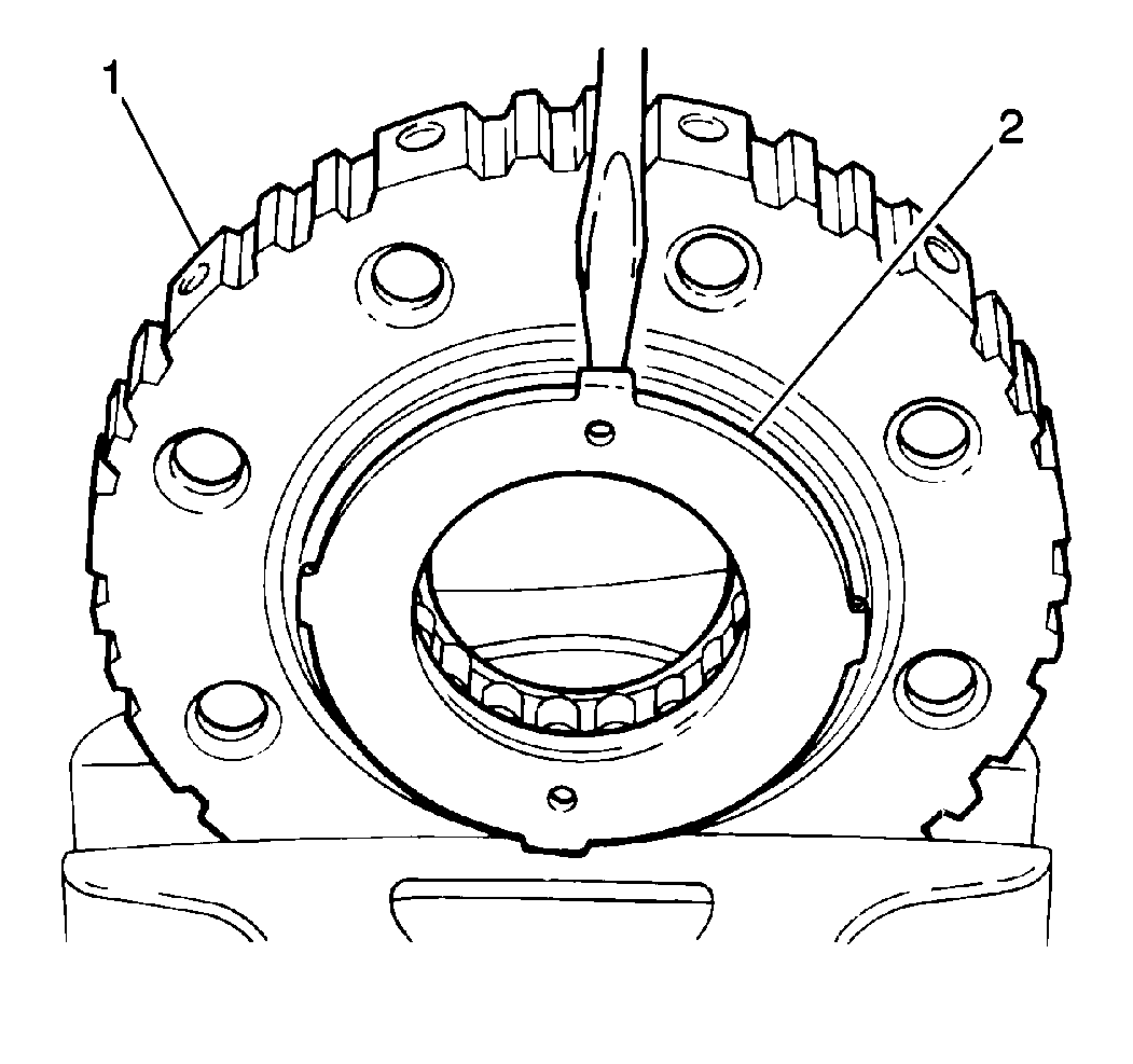
- Remove the rear thrust plate from the intermediate brake hub (1).
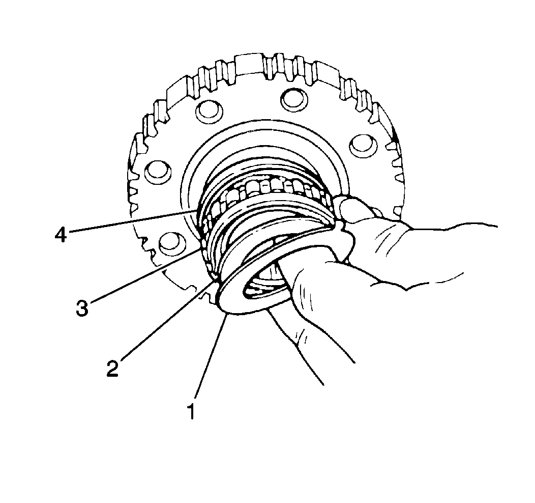
- Remove the intermediate one-way clutch retainers and the sprag assembly from the intermediate brake hub (4).
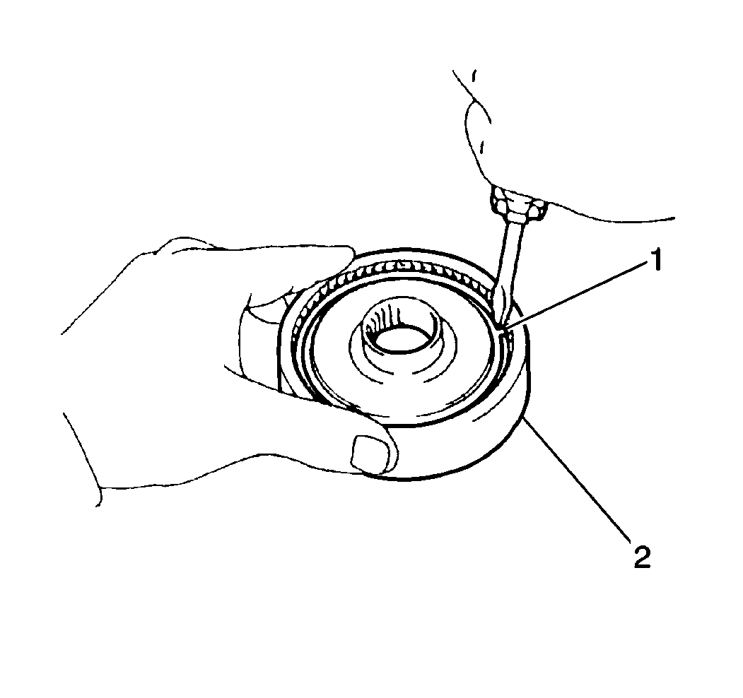
- Remove the front planetary ring gear flange snap ring (1) from the front
planetary ring gear.
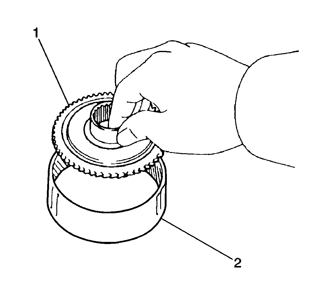
- Remove the front planetary ring gear flange (2) from the front planetary ring gear (1).
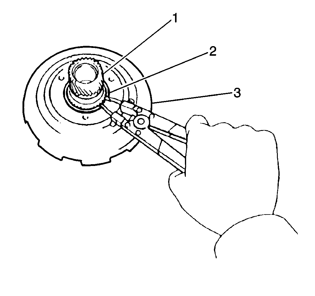
- Remove the sun gear input drum snap ring (2) from the sun gear at the rear of the sun gear input drum.
- Remove the sun gear (1) from the sun gear input drum (3).
- Remove the sun gear snap ring from the sun gear.
- Clean all components of the front planetary gearset and the sun gear input and dry these components thoroughly.
- Inspect the following components for excessive wear or damage. Replace the intermediate brake hub assembly as necessary:
| • | The intermediate one-way clutch outer race |
- Inspect the following components for excessive wear or damage and replace as necessary:
| • | The front planetary ring gear |
| • | The front planetary carrier pinion gears |
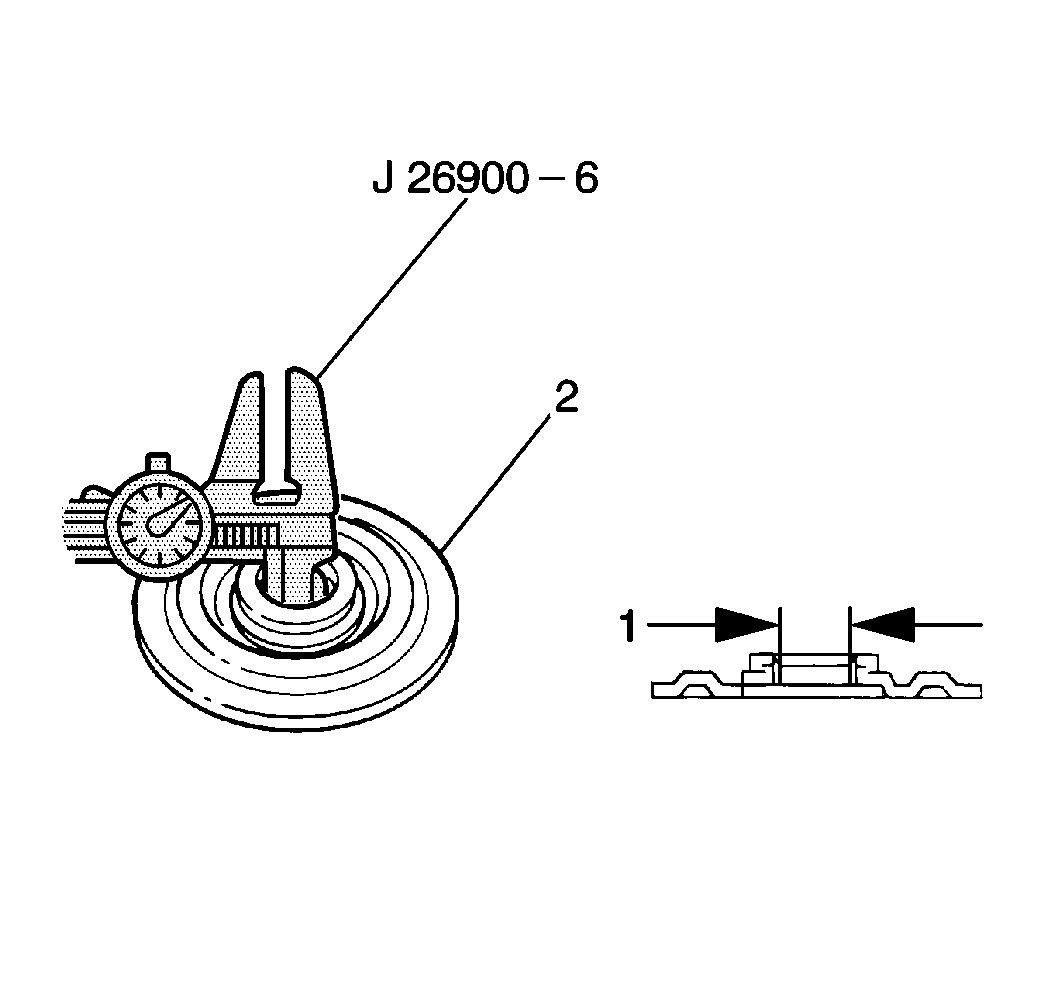
- Use a
J 26900-6
in order to measure the front planetary ring gear flange bushing inside diameter (2).
| • | The standard front planetary ring gear flange bushing inside diameter should fall within 19.025-19.050 mm (0.7490-0.7500 in). |
| • | If the front planetary ring gear flange bushing inside diameter is greater than 19.050 mm (0.7500 in), replace the front planetary ring gear flange. |
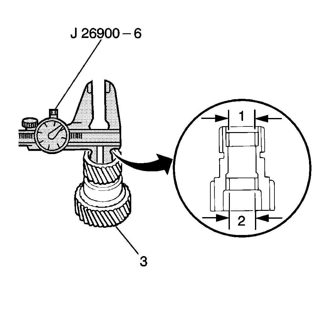
- Use the
J 26900-6
in order
to measure the sun gear flange bushing inside diameter.
| • | The standard sun gear flange bushing inside diameter (1) should fall within 22.025-22.046 mm (0.8671-0.8680 in). |
| • | The maximum sun gear flange bushing inside diameter (2) is 22.096 mm (0.8699 in). |
| • | If the sun gear flange bushing inside diameter is greater than specified, replace the sun gear. |
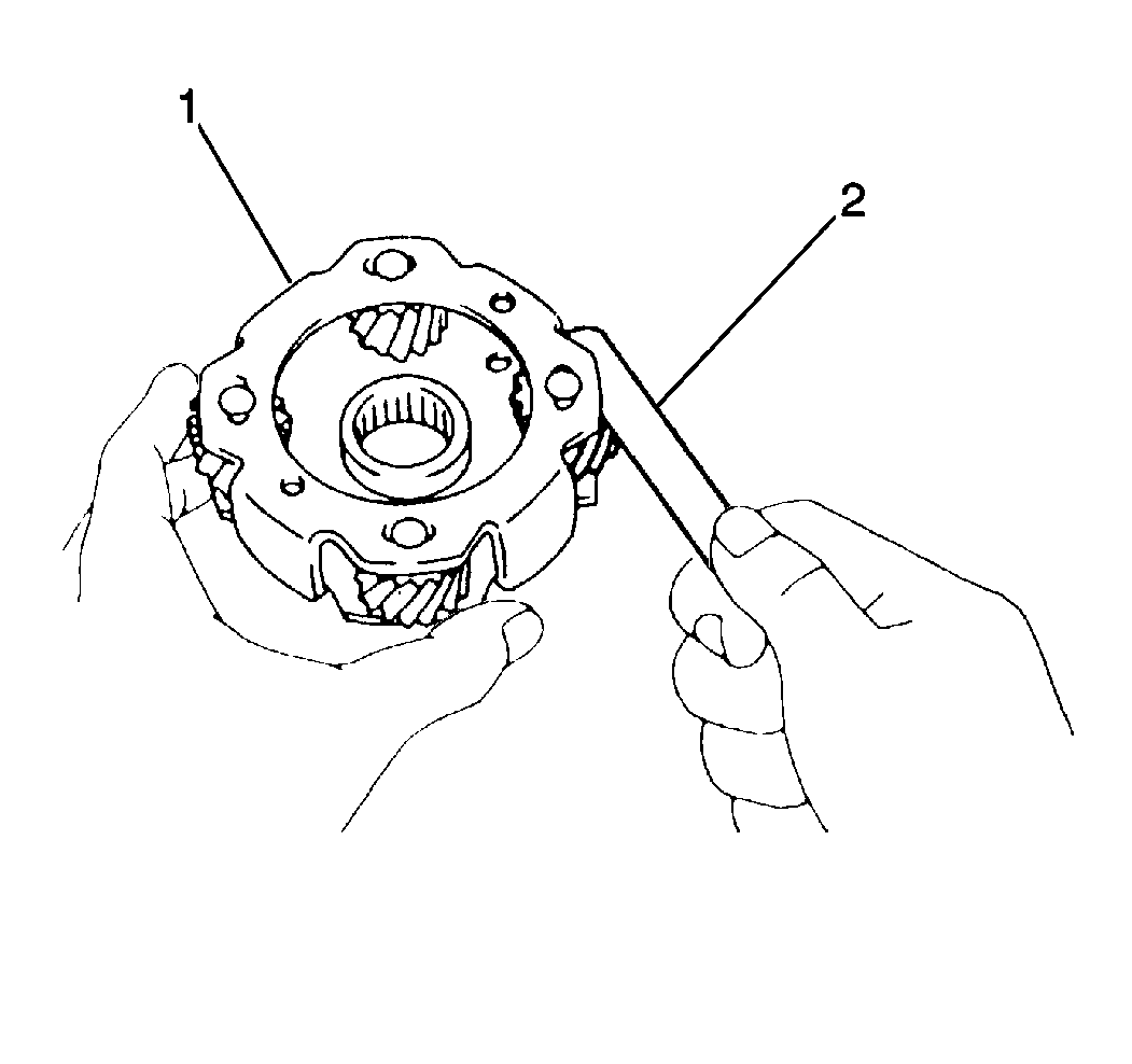
- Use a feeler gage (2) in order to measure the
front planetary carrier pinion gear thrust clearance.
| • | The standard front planetary carrier pinion gear thrust clearance should fall within 0.20-0.50 mm (0.008-0.020 in). |
| • | If the front planetary carrier pinion gear thrust clearance is greater than 0.50 mm (0.020 in), replace the front planetary carrier. |
Installation Procedure
- Install the sun gear snap ring onto the sun gear.
- Install the sun gear into the sun gear input drum.
- Install the sun gear input drum snap ring onto the sun gear at the rear of the sun gear input drum.
- Install the front planetary ring gear flange into the front planetary ring gear; secure with the front planetary ring gear flange snap ring.
- Install the intermediate one-way clutch sprag assembly and retainers into the intermediate brake hub.
- Install the rear thrust plate onto the intermediate brake hub.

- Inspect the intermediate one-way clutch after assembly by placing the intermediate brake hub and intermediate
one-way clutch onto the rear of the sun gear input drum, holding the sun gear input drum stationary and rotating the intermediate brake hub.
| • | The intermediate brake hub should turn freely in a clockwise direction (2) and should not turn in a counterclockwise direction (4). |
| • | If the intermediate brake hub is installed correctly on the sun gear input drum and the intermediate brake hub can be turned counterclockwise, replace the intermediate brake hub and the intermediate one-way clutch. |
First Reverse Brake Assembly Replacement
Removal Procedure
- Remove the two 1st-reverse brake piston seals from the 1st-reverse brake piston.
- Clean all the 1st-reverse brake components and dry thoroughly.
- Inspect the 1st-reverse brake discs for excessive wear or damage and replace as necessary.
- Inspect the 1st-reverse brake piston for cracks or porosity and replace as necessary.
- Inspect the 1st-reverse brake piston return spring for distortion or weakness and replace as necessary.
Installation Procedure
Install the new 1st-reverse brake piston seals onto the 1st-reverse brake piston.
Underdrive Clutch Assembly Replacement
Tools Required
| • | J 7872
Magnetic Base Indicator Set |
Removal Procedure
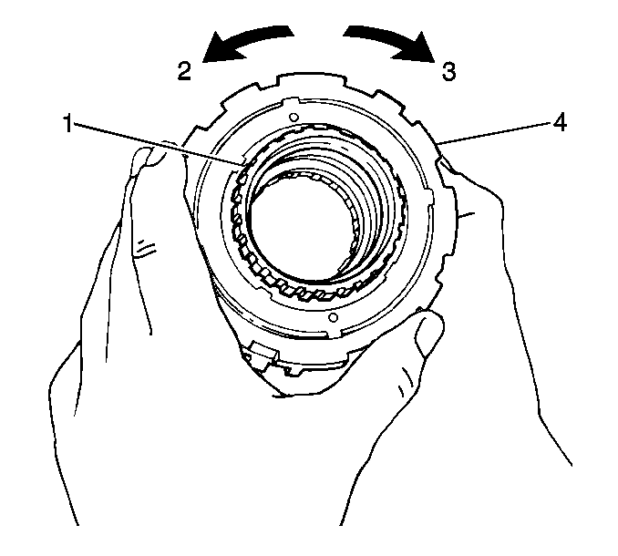
- Inspect the underdrive one-way clutch before disassembly by placing the underdrive one-way clutch onto the
rear of the underdrive clutch drum, holding the underdrive clutch drum stationary and rotating the underdrive one-way clutch.
- The underdrive one-way clutch should turn freely in a counterclockwise direction (2) and should not turn in a clockwise direction (3). If the underdrive one-way clutch is installed correctly on the underdrive clutch drum and the underdrive
one-way clutch can be turned clockwise, replace the underdrive one-way clutch.
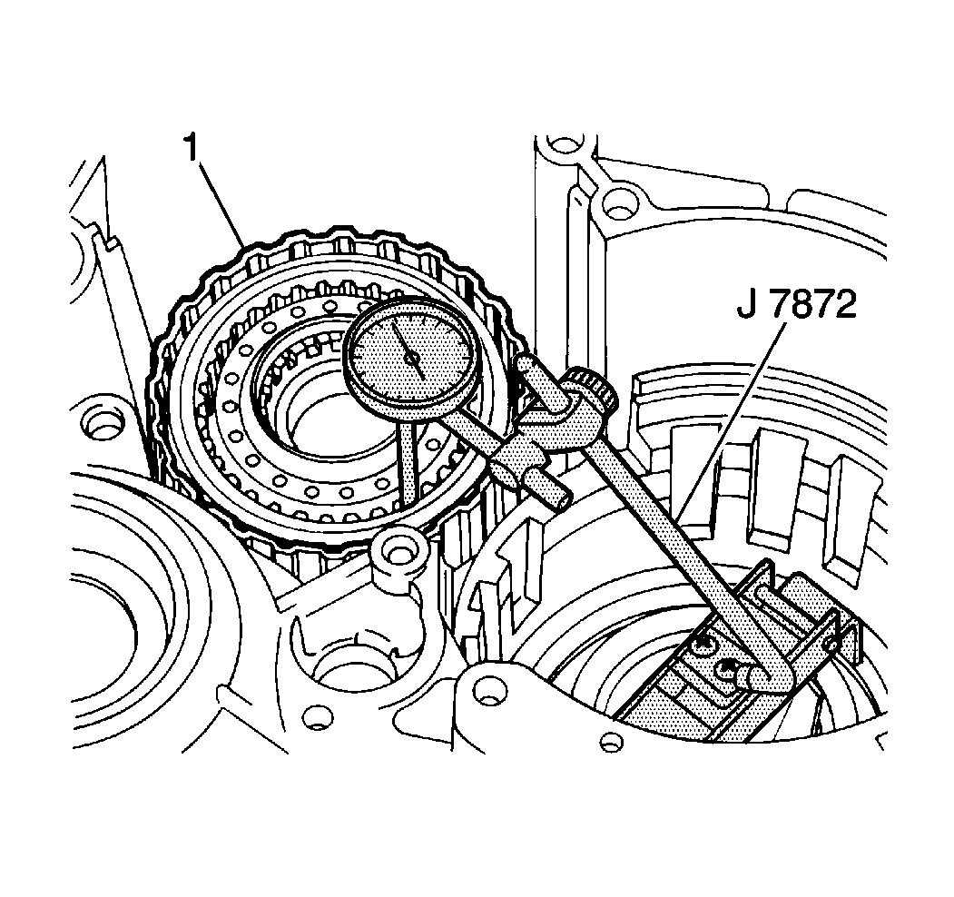
- Use a
J 7872
to measure the underdrive clutch (1)
piston stroke before disassembly.
| • | Temporarily install the old underdrive clutch drum support seal rings on the underdrive clutch drum support in the transaxle case. |
| • | Place the underdrive clutch drum on the underdrive clutch drum support in the transaxle case and the
J 7872
plunger on the underdrive clutch piston. |
- Apply 392-785 kPa (57-114 psi) of compressed air into the underdrive clutch apply passage (1) in
the transaxle case and observe the
J 7872
.
| • | The standard underdrive clutch piston stroke should fall within 1.500-1.900 mm (0.0590-0.0748 in). |
| • | If the underdrive clutch piston stroke is greater or less than specified, inspect all underdrive clutch components for excessive wear. |
Caution: Wear safety glasses in order to avoid eye damage.
Notice: The underdrive one-way clutch should be disassembled for inspection
purposes only. If excessive wear or damage is found in any component of the
underdrive one-way clutch upon inspection, replace the underdrive one-way
clutch as an assembly.
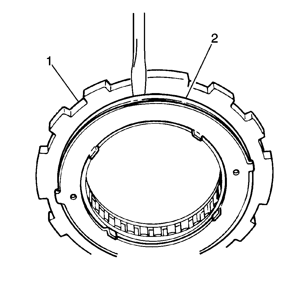
- Remove the rear thrust plate (2) from the underdrive one-way clutch outer race (1).
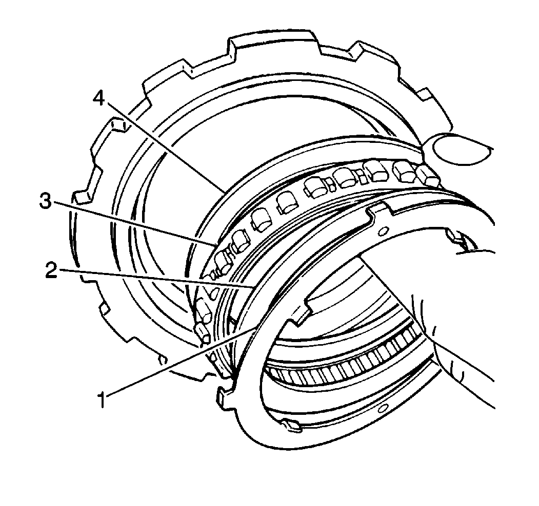
- Remove the underdrive one-way clutch retainers (2, 4) and the sprag assembly (3) from the underdrive
one-way clutch outer race.
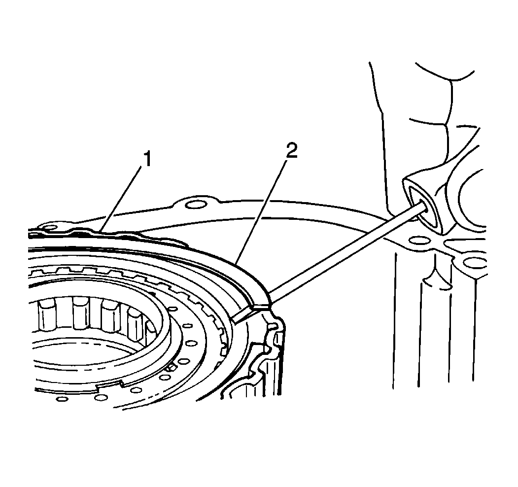
- Remove the underdrive clutch snap ring (2) from the underdrive clutch drum (1).
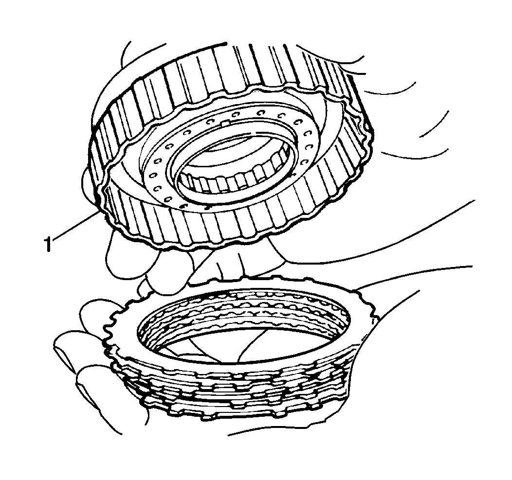
- Remove the following components from the underdrive clutch drum (1):
| • | The underdrive clutch flange |
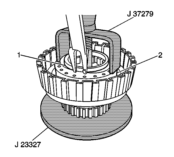
- Use a
J 23327
with a
J 37279
to remove the underdrive clutch piston return spring snap ring (1) from the underdrive piston return spring (2).
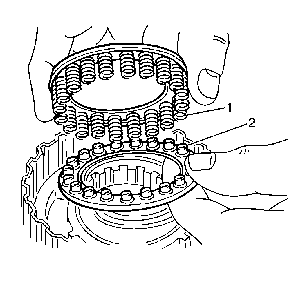
- Remove the following components from the
underdrive clutch piston:
| • | The underdrive clutch piston return spring (1) |
| • | The underdrive clutch piston return spring plate (2) |

Important: When using compressed air to remove components, air pressure should not exceed 98 kPa (14 psi).
- Remove the underdrive clutch piston from the underdrive clutch drum by placing the underdrive clutch drum on the underdrive clutch drum support in the transaxle case and applying low pressure compressed air into the underdrive clutch apply passage (1)
in the transaxle case (2).
- Remove the underdrive clutch drum from the underdrive clutch drum support in the transaxle case.
- Inspect the following components for excessive wear or damage and replace the underdrive one-way clutch assembly as necessary:
| • | The underdrive one-way clutch sprag assembly |
| • | The underdrive one-way clutch outer race |
- Inspect the underdrive clutch discs for excessive wear or damage and replace as necessary.
- Inspect the underdrive clutch piston for cracks or porosity and replace as necessary.
- Inspect the underdrive clutch piston check ball operation by applying compressed air into the working and release sides of the underdrive clutch piston.
- There must be no air leakage on the working side and air must pass freely through the release side. If these conditions do not exist, replace the underdrive clutch piston.
- Inspect the underdrive clutch piston return spring for distortion or weakness and replace as necessary.
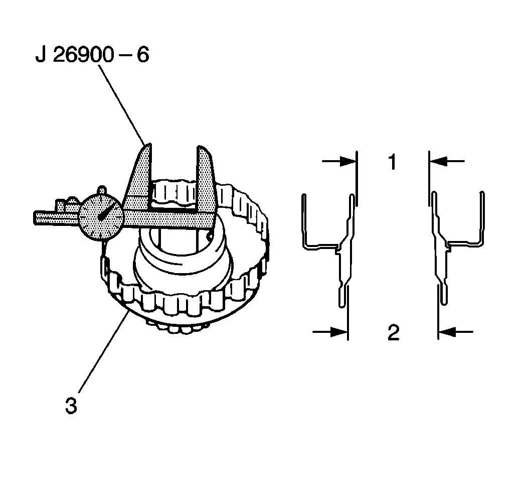
- Use a
J 26900-6
to measure
the inside diameter of the front and rear underdrive clutch flange (3) bushings.
| • | The standard underdrive clutch flange bushing diameter should measure within the following parameters: |
Specification
| • | Front (1) 46.500-46.525 mm (1.8307-1.8316 in).
|
| • | Rear (2) 55.000-55.030 mm (2.1653-2.1665 in).
|
| • | The maximum inside diameter of the underdrive clutch bushing should measure within the following parameters: |
Specification
| • | Front 46.570 mm (1.8334 in)
|
| • | Rear 55.080 mm (2.1685 in)
|
| • | If the inside diameter of the underdrive clutch bushings are greater than specified, replace the underdrive clutch drum. |
Installation Procedure
Caution: Wear safety glasses in order to avoid eye damage.
Notice: When installing new clutch discs in the 1st-reverse brake, forward clutch
or direct clutch assemblies, the new clutch discs MUST be soaked in Dexron®
- III automatic transmission fluid GM P/N 12341643, or equivalent,
two hours prior to installation. This causes the clutch material on the discs
to permeate with fluid which will aid in ease of assembly and prevent clutch
overheating on first time engagement.
Important: When using compressed air to remove components, air pressure should not exceed 98 kPa (14 psi).
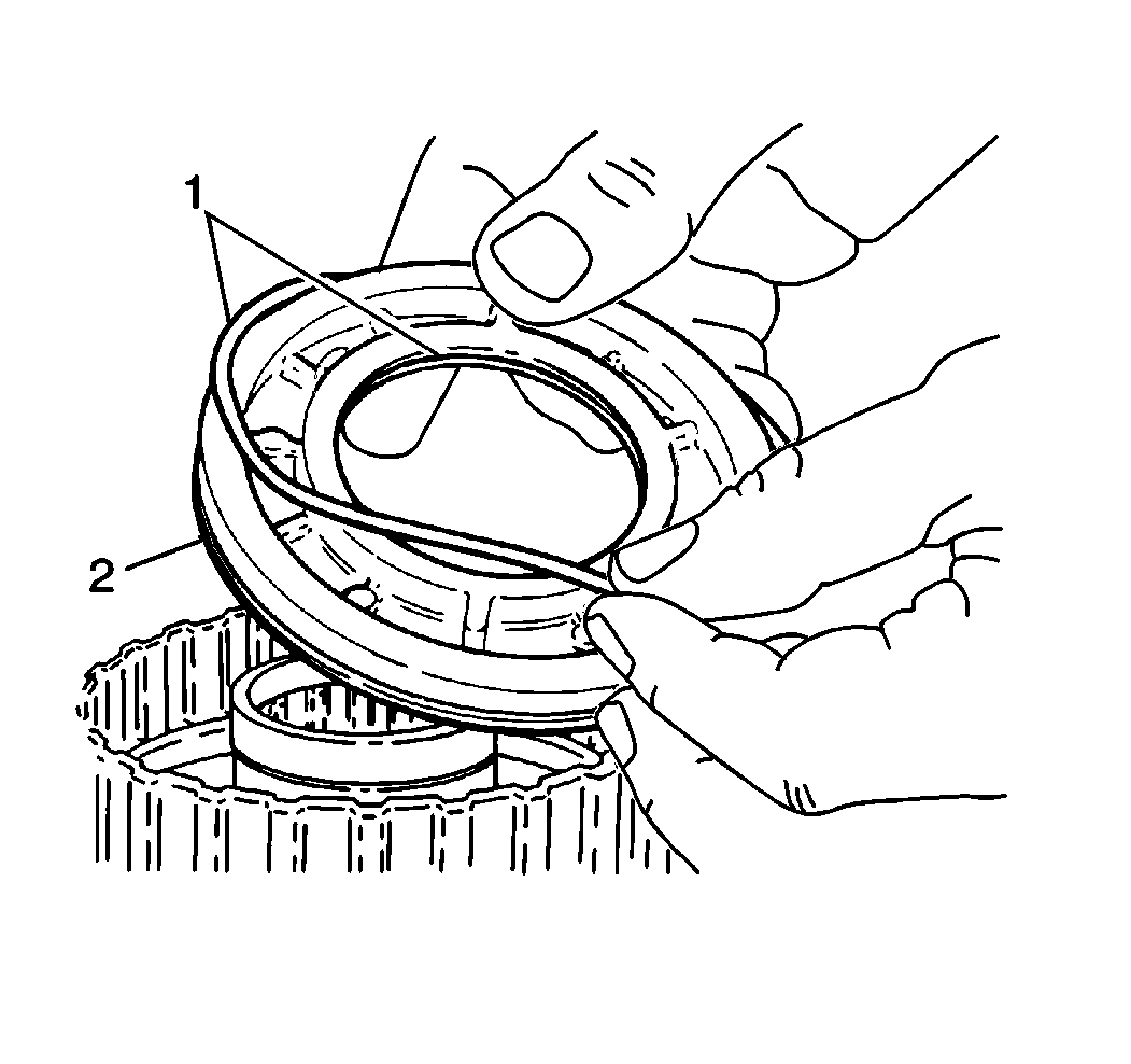
- Install the two underdrive clutch piston seals (1) onto the underdrive clutch piston (2).
- Apply
J 36850
to the new underdrive clutch piston seals.
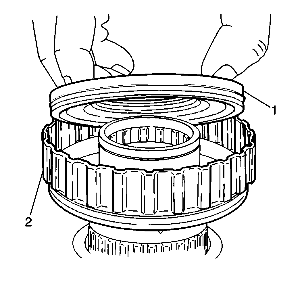
- Install the underdrive clutch piston (1) into the underdrive clutch drum (2).
- Install the underdrive clutch piston return spring and the underdrive clutch piston return spring into the underdrive clutch piston.

- Use a
J 23327
with a
J 37279
to install the underdrive clutch piston return spring snap ring onto the underdrive piston return spring (2).

- Install the 4 discs, 4 plates and underdrive clutch flange into the
underdrive clutch drum (1) in the following order:
Important: The underdrive clutch flange must be installed with the flat side facing down and the stepped portion facing upwards.
- Install the flange.
- Install the underdrive clutch snap ring into the underdrive clutch drum.
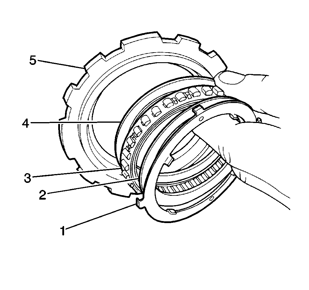
- Install the underdrive one-way clutch sprag assembly (3) and retainers (2, 4) into the underdrive one-way clutch outer
race (5).
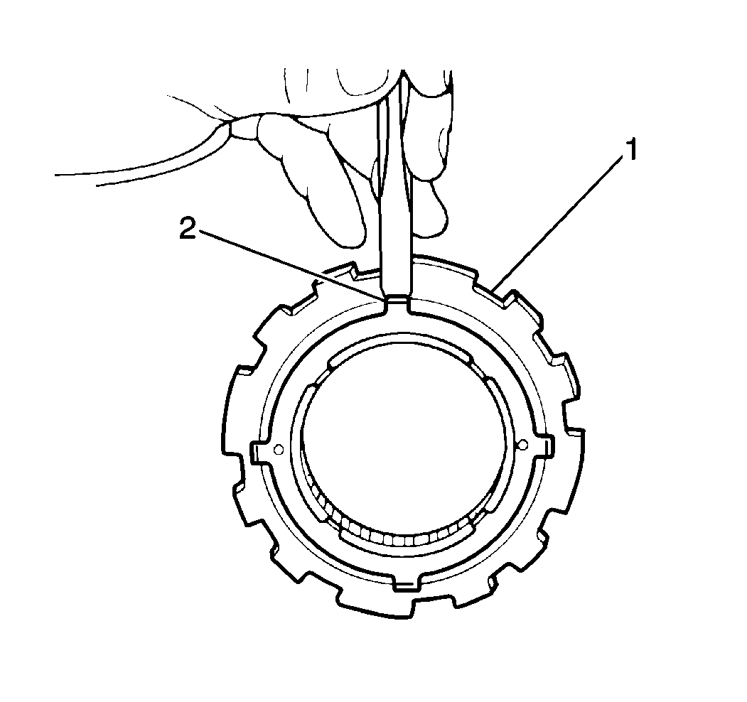
- Install the rear thrust plate (2) onto the underdrive one-way clutch outer
race (1).

- Use a
J 7872
to measure the underdrive clutch piston stroke
after assembly.
- Place the underdrive clutch drum (1) on the underdrive clutch drum support in the transaxle case and the
J 7872
plunger on the underdrive clutch piston.

- Apply 392-785 kPa (57-114 psi) of compressed air into the underdrive clutch apply passage (1) in
the transaxle case and observe the
J 7872
| • | The standard underdrive clutch piston stroke should fall within 1.500-1.900 mm (0.0590- 0.0748 in). |
| • | If the underdrive clutch piston stroke does not fall within specification, select one of the two following underdrive clutch flange sizes to bring the underdrive clutch piston stroke within specification: |
Specification
| • | Remove the old underdrive clutch drum support seal rings from the underdrive clutch drum support. |

- Inspect the underdrive one-way clutch after assembly by placing the underdrive one-way clutch onto the rear
of the underdrive clutch drum, holding the underdrive clutch drum stationary and rotating the underdrive one-way clutch.
| • | The underdrive one-way clutch (1) should turn freely in a counterclockwise direction (2) and should not turn in a clockwise direction (3). |
| • | If the underdrive one-way clutch is installed correctly on the underdrive clutch drum and the underdrive one-way clutch can be turned clockwise, replace the underdrive one-way clutch. |
Underdrive Brake Assembly Replacement
Removal Procedure
- Remove the 2 underdrive brake piston seals from the underdrive brake piston.
- Clean all the underdrive brake components and dry thoroughly.
- Inspect the underdrive brake discs for excessive wear or damage and replace as necessary.
- Inspect the underdrive brake piston for cracks or porosity and replace as necessary.
- Inspect the underdrive brake piston return spring for distortion or weakness and replace as necessary.
Installation Procedure
Install the new underdrive brake piston seals onto the underdrive piston.
Differential Side Bearing Preload Adjustment
Tools Required
| • | J 35405
Differential Preload Wrench |
| • | J 26941
Countershaft Bearing Drive Axle Seal Remover |
| • | J 35552
Differential Side Bearing Cup Installer |
Adjustment Procedure
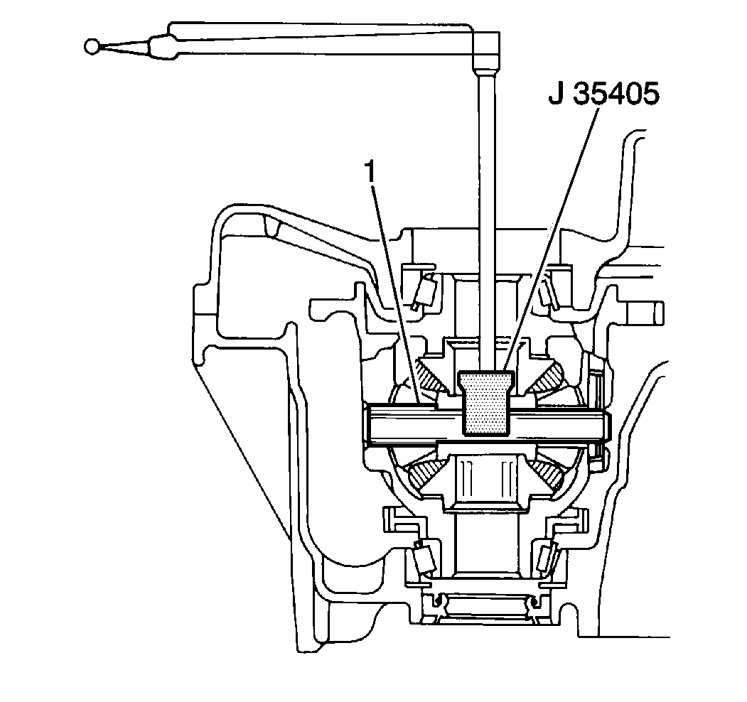
- Insert the
J 35405
into the drive axle shaft bore in
the torque converter housing until the
J 35405
engages with the pinion shaft (1) of the differential.
- Rotate the differential several times in both directions in order to ensure that the differential bearings have seated. Measure the differential side bearing preload. Standard differential side bearing preload should fall within the following ranges:
| • | New differential side bearings 0.8-1.4 N·m (7-12 lb in) |
| • | Reused differential side bearings 0.4-0.7 N·m (4-6 lb in). |
Important: Differential side bearing selective shims sizes are available in increments of 0.05 mm (0.002 in). Refer to Differential Side Bearing Selective Shim Sizes Table in
Transmission General Specifications
- Differential side bearing preload (differential starting torque) will change approximately 0.3-0.4 N·m (2.5-3.5 lb in) by increasing or decreasing one shim size.
- If the differential side bearing preload is below specification, increase the size of the left differential side bearing selective shim in the transaxle case. If the differential side bearing preload is above specification, decrease the size of the
left differential side bearing selective shim in the transaxle case.
| 4.1. | Remove the 17 torque converter bolts and the torque converter housing from the transaxle case. |
| 4.2. | Remove the differential assembly from the transaxle case. |
| 4.3. | Use the
J 26941
with the
J 2619-01
in order to remove the left differential side bearing race and the selective shim. |
| 4.4. | Use the
J 35552
with the
J 8092
and a hammer in order to install an appropriate size left differential side bearing selective shim and race
into the transaxle case. |
Refer to
Transmission General Specifications
.
Underdrive Brake Assembly Installation
Tools Required
Important: When installing new clutch discs in the 1st-reverse brake, the underdrive brake, the underdrive clutch, the intermediate brake, the forward clutch or the direct clutch assemblies, the new clutch discs MUST be soaked in
Dexron®-III Automatic Transmission Fluid GM P/N 12346143 or equivalent, two hours prior to installation. This causes the clutch material on the discs to permeate with fluid which will aid in ease of assembly and prevent clutch overheating on
first time engagement.
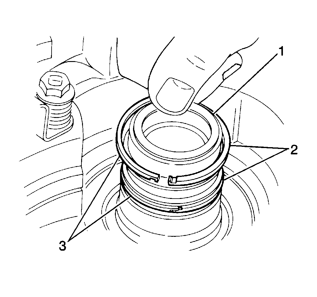
- Install the 2 new seal rings onto the underdrive clutch drum support (2).
- Apply
J 36850
in order to the two new underdrive clutch drum support seal rings (3).
- Apply
J 36850
in order to the two new underdrive brake piston seals.
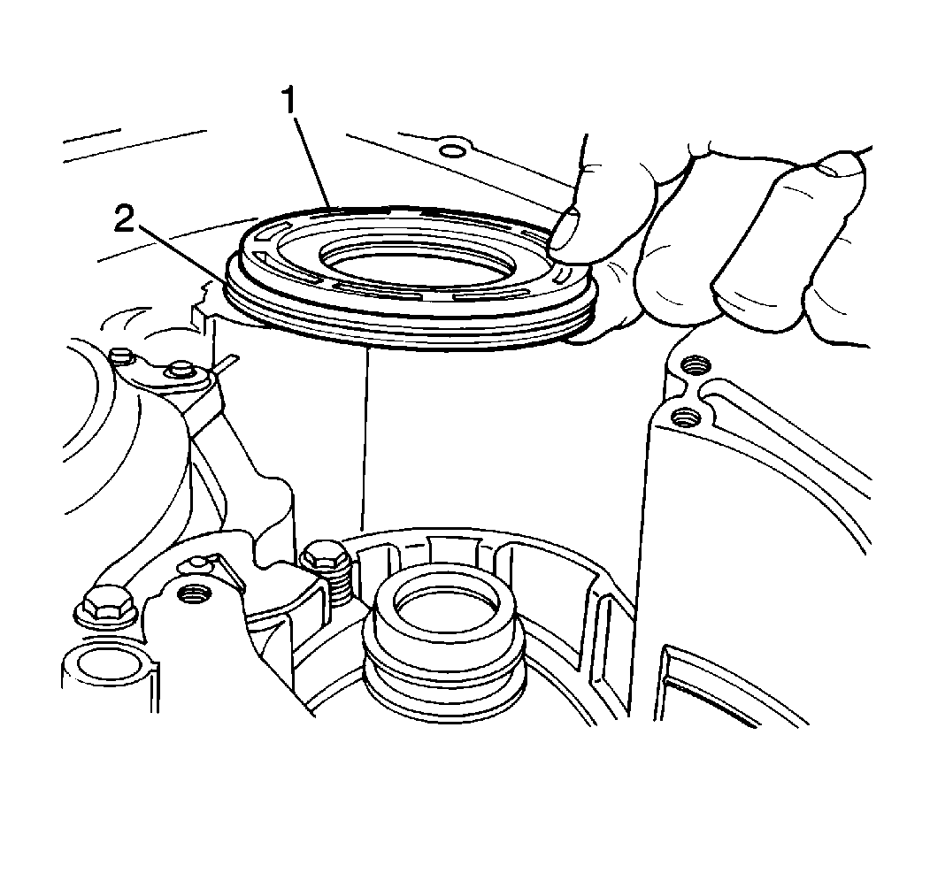
- Install the underdrive brake piston (1) into the transaxle case with the cup side facing upwards.
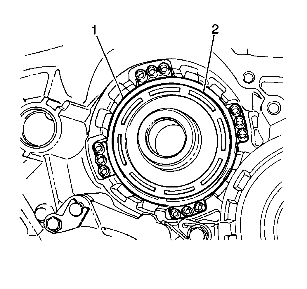
- Install the underdrive brake piston return spring (1) into the transaxle
case.
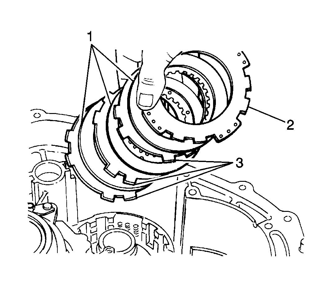
- Install the underdrive brake flange (2), three plates (3) and three
discs (1) into the transaxle case in the following order:
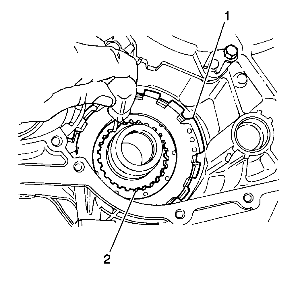
- Align the inner teeth of the underdrive brake discs (2).
- Install the
J 23327
with the
J 37282
into the transaxle case and compress the underdrive brake piston return spring until the underdrive brake
piston return spring snap ring can be installed.
- Install the underdrive brake snap ring into the transaxle case.
- Remove the
J 37282
and the
J 23327
from the transaxle case.

- Measure the underdrive brake assembly (1) using a
J 7872
. Apply 392-785 kPa (57-114 psi) of compressed air into the underdrive brake apply passage (2).
| • | Verify that the underdrive brake assembly clearance falls within 1.07-2.05 mm (0.0421-0.0807 in). |
| • | If the underdrive brake assembly clearance does not fall within specification, inspect the underdrive brake assembly for excessive wear. |
Underdrive Clutch Assembly Installation
Tools Required

- Inspect the underdrive one-way clutch for correct installation by simultaneously placing the underdrive one-way
clutch onto the rear of the underdrive clutch drum (1), holding the underdrive clutch drum stationary and rotating the underdrive one-way clutch (4) by hand.
| • | The underdrive one-way clutch must turn freely in a counterclockwise direction (2) for correct installation. If the underdrive one-way clutch turns freely in a clockwise direction (3), the underdrive one-way clutch is installed backwards
(upside down). |
| • | Remove the underdrive one-way clutch and reinstall correctly. |
| • | Repeat the above inspection to verify correct installation. |
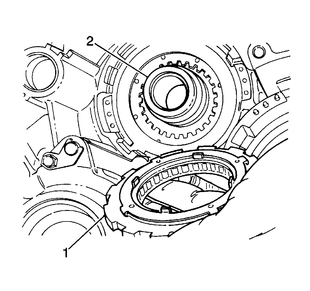
- Install the underdrive one-way clutch (1) into transaxle case.
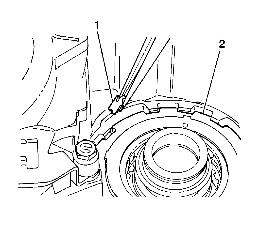
- Install the underdrive one-way clutch anti-rattle clip (1) into the transaxle
case.
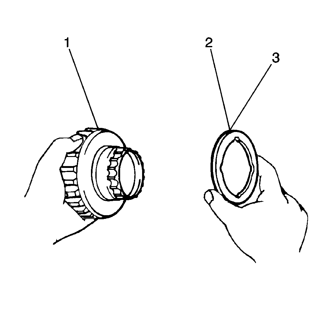
- Apply
J 36850
(3) to
the underdrive one-way clutch thrust washer (2) in order to hold it in place on the rear of the underdrive clutch drum (1).
- Install the underdrive one-way clutch thrust washer in order to hold it in place on the rear of the underdrive clutch drum.
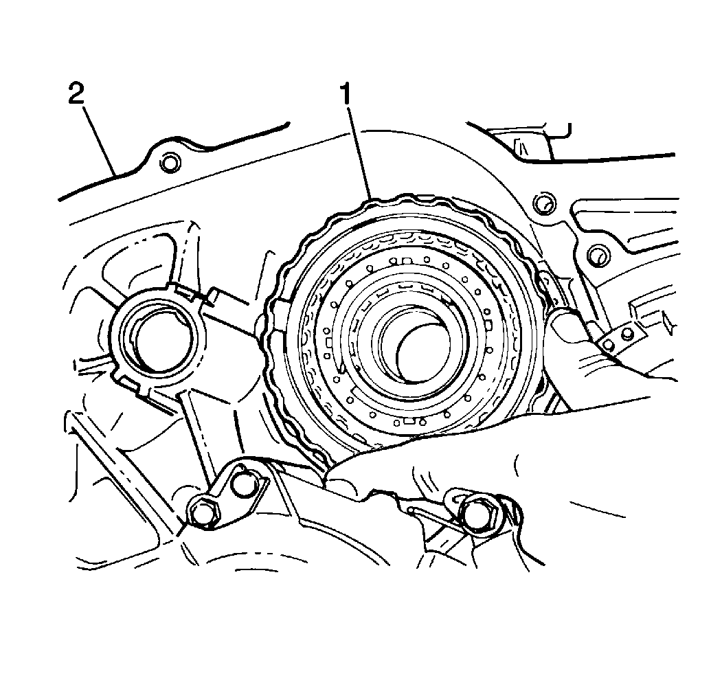
- Install the underdrive one-way clutch assembly (1) into the underdrive one-way clutch and underdrive brake assembly.
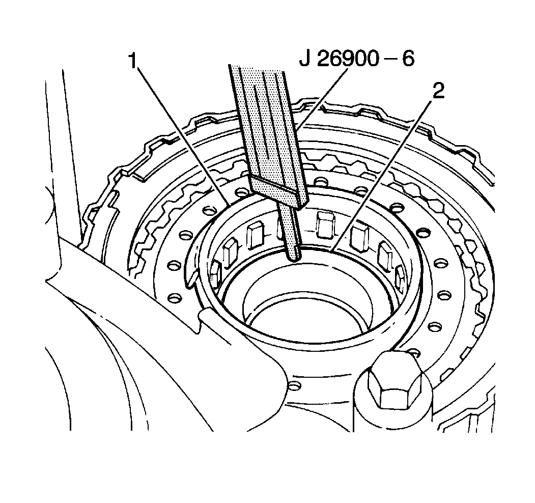
- Measure the underdrive clutch assembly installation depth using a
J 26900-6
| • | Measure the installation depth from the top of the underdrive clutch drum support (2) to the top of the underdrive clutch drum (1). The underdrive clutch assembly installation depth should fall within 17.3-18.2 mm (0.681-0.717 in). |
| • | If the underdrive clutch assembly installation depth does not fall within specification, remove the underdrive clutch assembly and repeat the underdrive clutch assembly installation procedure until the underdrive clutch assembly installation depth
is within specification. |
First Reverse Brake Assembly Installation
Important: When installing new clutch discs in the 1st-reverse brake, the underdrive brake, the underdrive clutch, the intermediate brake, the forward clutch or the direct clutch assemblies, the new clutch discs MUST be soaked in
Dexron®-III Automatic Transmission Fluid GM P/N 12346143 or equivalent, two hours prior to installation. This causes the clutch material on the discs to permeate with fluid which will aid in ease of assembly and prevent clutch overheating on first time engagement.
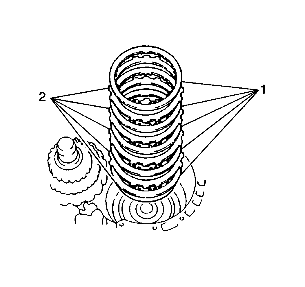
- Install the five plates (2) and the five discs (1) in the transaxle
case in the following order:
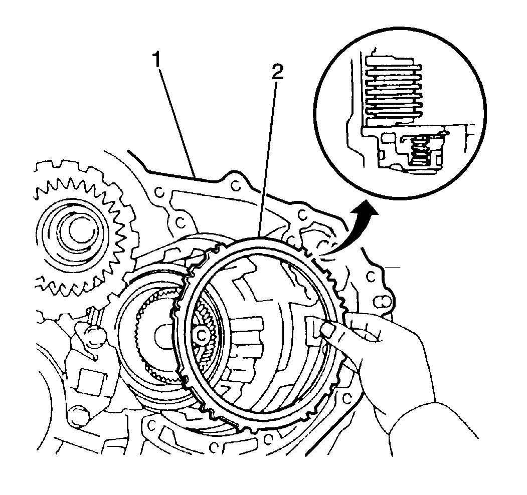
Important: The 1st-reverse brake flange must be installed with the flat side facing down and the stepped portion facing upwards.
- Install the 1st-reverse brake flange (2).
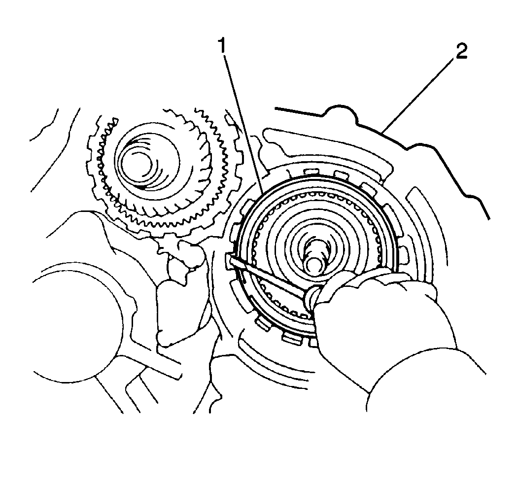
- Install the 1st-reverse brake snap ring (1) into the transaxle case (2).
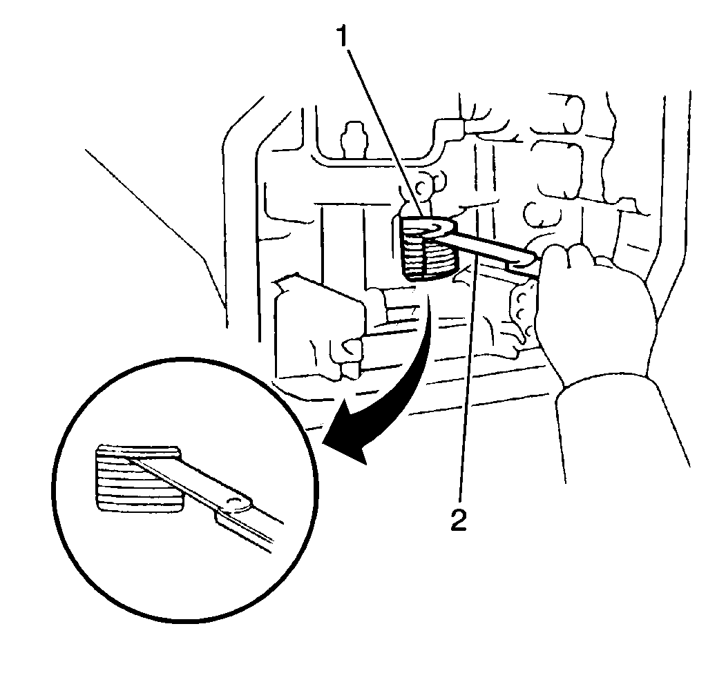
- Measure the 1st-reverse brake assembly clearance using a feeler gage (2).
| • | The 1st-reverse brake assembly clearance should fall within 1.06-2.38 mm (0.04170-0.0937 in). |
| • | If the 1st-reverse brake assembly clearance is above 1.06 mm (0.0417 in), inspect the 1st-reverse brake assembly for excessive wear. |
Second Coast Brake Installation
Tools Required
Notice: If the 2nd coast brake band appears excessively worn or damaged and
replacement is necessary, the new brake band should be soaked in Dexron®-III
Automatic Transmission Fluid GM P/N 12346143, or equivalent, for
two hours prior to installation. This causes the band material to permeate
with fluid which will prevent the band overheating on first time application.
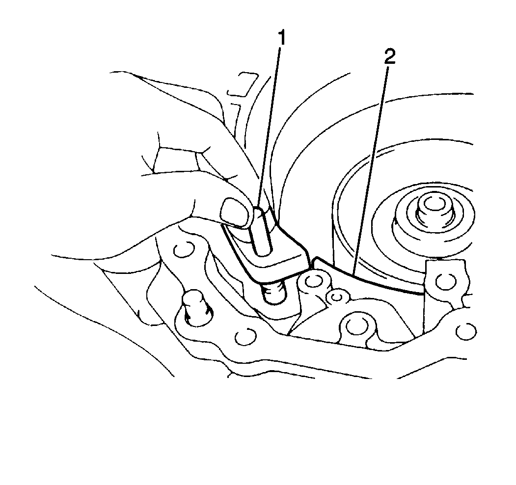
- Install the 2nd coast brake band (2) into the transaxle case. Secure the brake band with the 2nd coast brake band anchor pin (1).
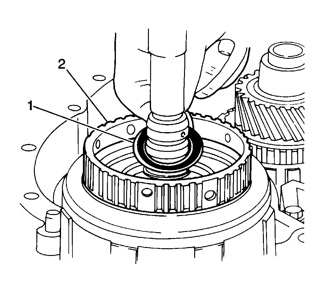
- Apply
J 36850
to the outer forward clutch thrust bearing.
- Install the forward clutch outer thrust bearing (1) over the input shaft and into the forward clutch drum.
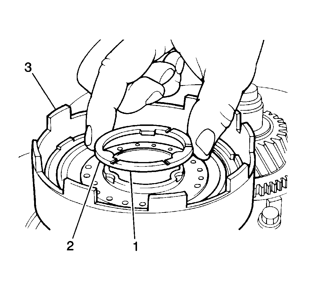
Important: During direct clutch thrust washer installation, verify that the oil grooves (brass surface) are facing toward the forward clutch.
-
Apply
J 36850
(1) to the direct clutch thrust washer (2) in order to hold it in place on the direct clutch drum.
- Install the direct clutch thrust washer onto direct clutch drum.
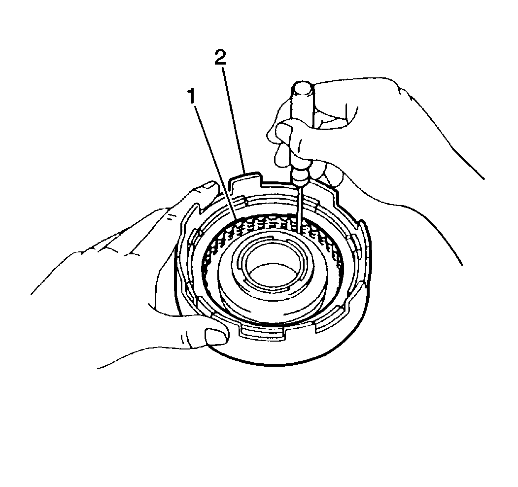
- Align the inner teeth of the direct clutch discs (1).
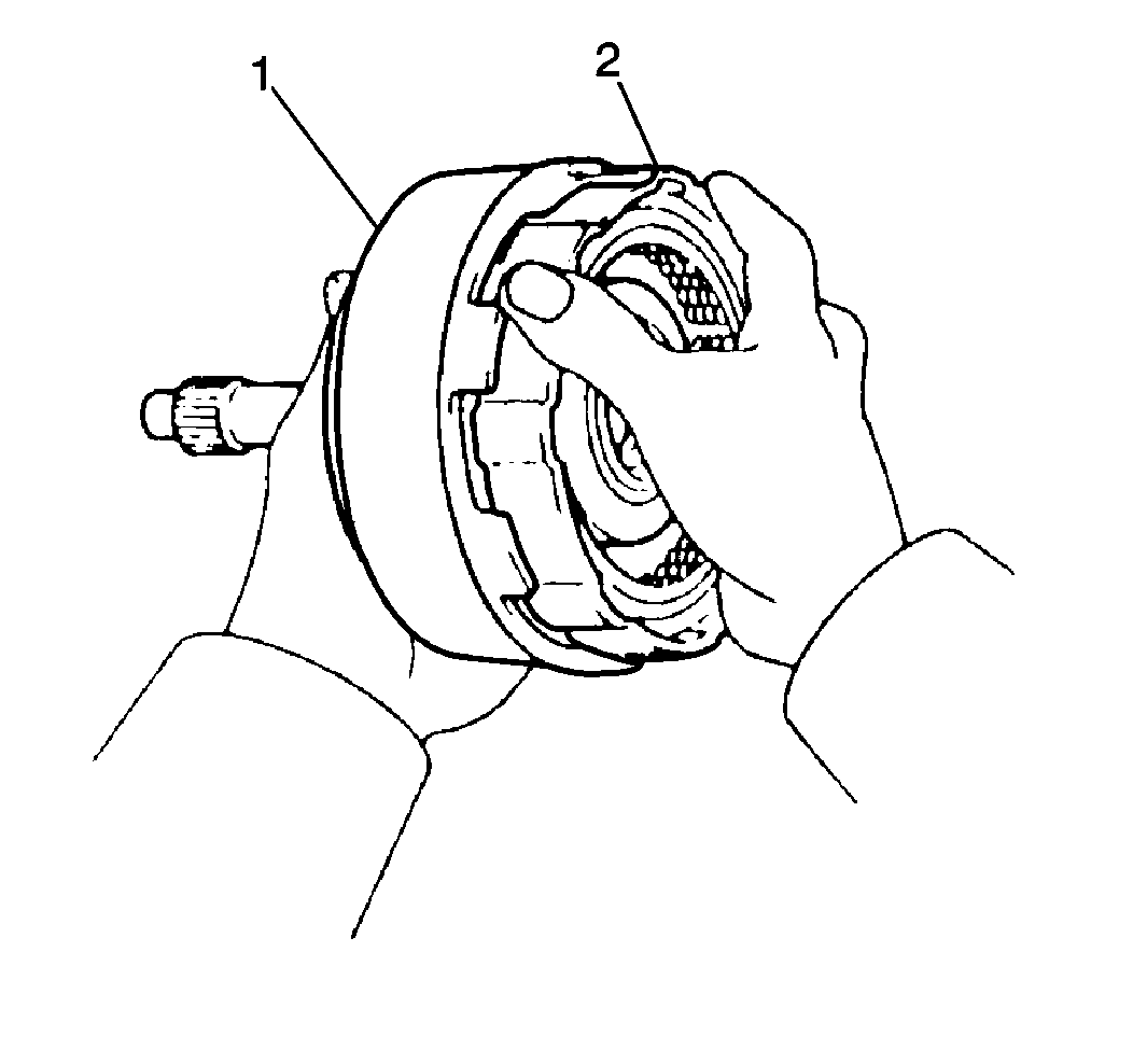
- Install the direct clutch assembly (1) onto the forward clutch assembly (2)
by rotating the direct clutch drum back and forth until the direct clutch inner teeth of the direct clutch discs mesh with the forward clutch drum.
- Align the inner teeth of the forward clutch discs.
- Apply
J 36850
to the forward clutch inner thrust bearing in order to hold it in place in the center of the forward clutch drum.
- Install the forward clutch inner thrust bearing into the center of the forward clutch drum.
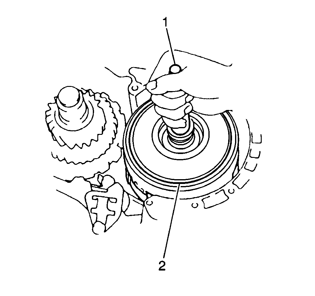
- Install the forward and direct clutch assemblies (2)
onto the front planetary ring gear by rotating the input shaft (1) back and forth until the inner teeth of the forward clutch discs mesh with the front planetary ring gear.
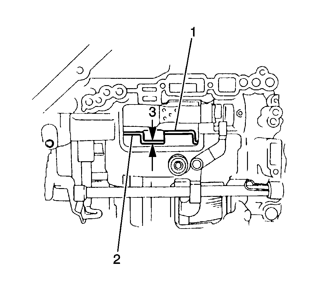
- Measure the installation depth of the
forward and the direct clutch assemblies by measuring the gap between the direct clutch drum (1) and the sun gear input drum using a
J 26900-6
- Verify that the gap between the direct clutch drum and the sun gear input drum (2) is approximately 3 mm (0.118 in) (3).
- If the gap between the direct clutch drum and the sun gear input drum is greater than specification, remove the forward and direct clutch assemblies and reinstall until the distance is within specification.
- Apply
J 36850
to the 2nd coast brake servo piston and cover seals.
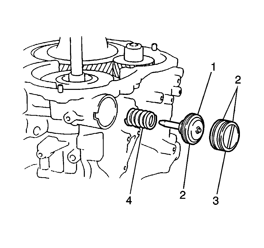
- Install the 2nd coast brake outer return spring (4), the 2nd coast brake
piston (1) and the 2nd coast brake servo cover (3) into the transaxle case.
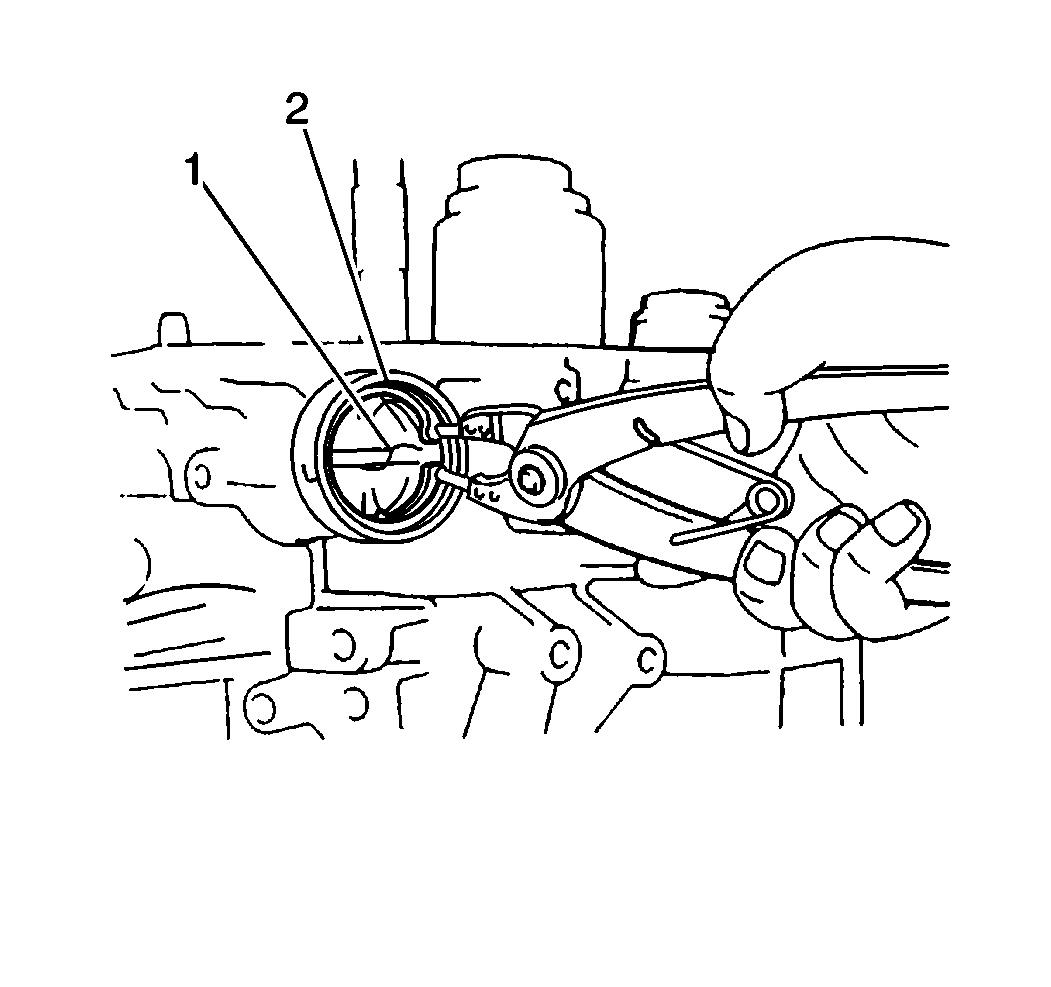
- Install the 2nd coast brake servo cover snap ring (2) into the transaxle
case.
- Measure the 2nd coast brake servo piston stroke.
| • | Place a reference mark on the 2nd coast brake piston rod where the piston rod meets the transaxle case. |
| • | Apply 392-785 kPa (57-114 psi) of compressed air into the 2nd coast brake apply passage. |
| • | Measure the distance between the reference mark and the transaxle case using a feeler gage to obtain the 2nd coast brake piston stroke. |
| • | Verify that the 2nd coast brake piston stroke falls within 1.5-3.5 mm (0.059-0.138 in). |
| • | If the 2nd coast brake piston stroke does not fall within specification, inspect the 2nd coast brake band for excessive wear or damage. |
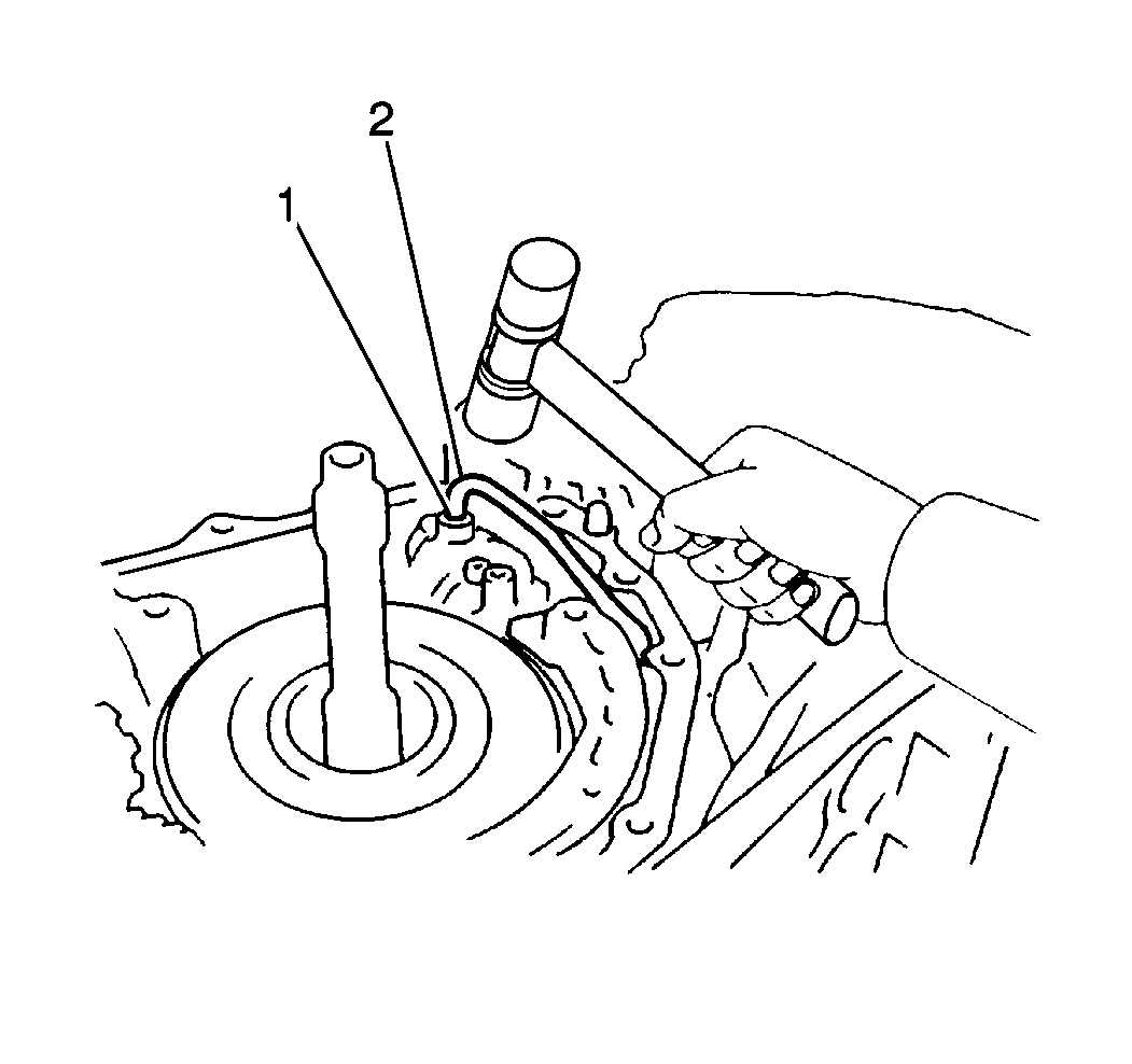
- Install the 2nd coast brake apply pipe (2) into the transaxle case.
Notice: Use the correct fastener in the correct location. Replacement fasteners
must be the correct part number for that application. Fasteners requiring
replacement or fasteners requiring the use of thread locking compound or sealant
are identified in the service procedure. Do not use paints, lubricants, or
corrosion inhibitors on fasteners or fastener joint surfaces unless specified.
These coatings affect fastener torque and joint clamping force and may damage
the fastener. Use the correct tightening sequence and specifications when
installing fasteners in order to avoid damage to parts and systems.
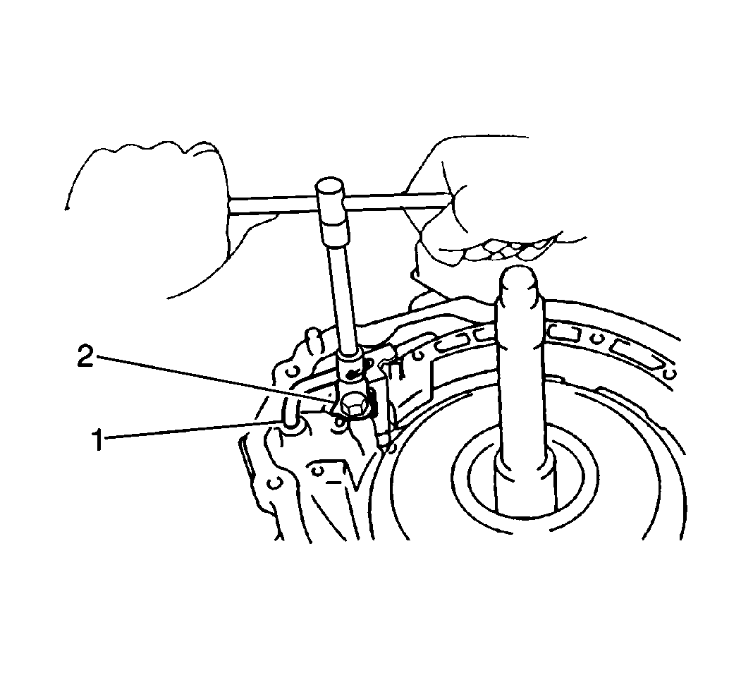
- Install the 2nd coast brake apply pipe bracket (2) into the transaxle case. Secure the pipe bracket with one bolt.
Tighten
Tighten the 2nd coast brake apply pipe bracket bolt to 5 N·m (44 lb in).


