Front Suspension Crossmember Replacement All Wheel Drive
Removal Procedure
Note: If you are removing the front suspension crossmember in order to gain access to other components, you may remove the following components together as a unit:
| • | The front suspension crossmember |
| • | The 2 lower control arms |
| • | The front stabilizer shaft |
- Remove the steering gear. Refer to
Steering Gear Replacement.
- Install the engine support fixture. Refer to
Engine Support Fixture.
- Raise and support the vehicle. Refer to
Lifting and Jacking the Vehicle.
- Remove the front tire and wheel assemblies from the vehicle. Refer to
Tire and Wheel Removal and Installation.
- Remove the left engine splash shield. Refer to
Engine Splash Shield Replacement - Left Side.
- Remove the right engine splash shield. Refer to
Engine Splash Shield Replacement - Right Side.
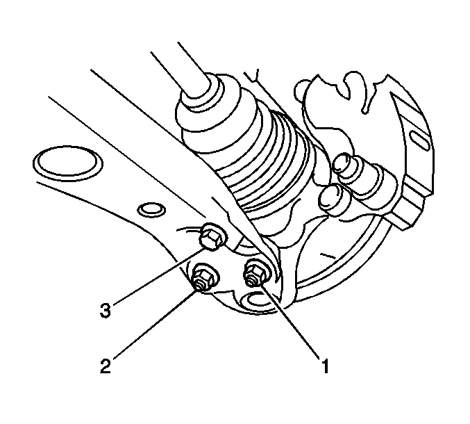
- Remove the following components from the left control arm:
- Remove the following components from the right control arm:
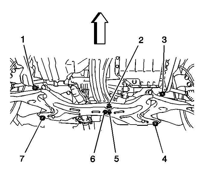
- Remove the 2 nuts (2, 5) and the bolt (6).
- Support the crossmember with a jack.
- Remove the 4 bolts (1, 3, 4, 7).
- Use the jack in order to lower the crossmember.
- Remove the steering gear from the crossmember.
Note: If you are replacing the components on front suspension crossmember, continue with this procedure.
- Remove the 2 control arms. Refer to
Lower Control Arm Replacement.
- Remove the following components from the crossmember. Refer to
Stabilizer Shaft Replacement.
| • | The 2 stabilizer shaft link nuts |
| • | The 2 stabilizer shaft links |
| • | The 4 stabilizer shaft insulator clamp bolts |
| • | The 2 stabilizer shaft insulator clamps |
| • | The 2 stabilizer shaft insulators |
Installation Procedure
Note: DO NOT tighten the nut and bolts completely. The weight of the vehicle must be on the tire and wheel assemblies before tightening the nut and the bolts.
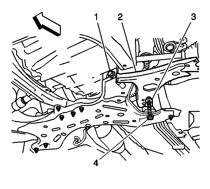
- Install the following components to the crossmember:
| • | The left lower control arm (2) |
Note: DO NOT tighten the nut and bolts completely. The weight of the vehicle must be on the tire and wheel assemblies before tightening the nut and the bolts.
- Install the following components to the crossmember:
| • | The right lower control arm |
- Install the following components to the crossmember. Refer to
Stabilizer Shaft Replacement.
| • | The 2 stabilizer shaft link nuts |
| • | The 2 stabilizer shaft links |
| • | The 4 stabilizer shaft insulator clamp bolts |
| • | The 2 stabilizer shaft insulator clamps |
| • | The 2 stabilizer shaft insulators |
- Use a jack in order to raise and support the crossmember with the attached components as a unit.
- Install the steering gear to the crossmember. Refer to
Steering Gear Replacement.
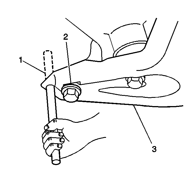
- Insert a wood dowel (1) into the hole in the right side of the crossmember (3) and the hole in the body.
- Use the dowel in order to align the bolt holes.
Note: DO NOT tighten the nut and bolts completely. The weight of the vehicle must be on the tire and wheel assemblies before tightening the nut and the bolts.
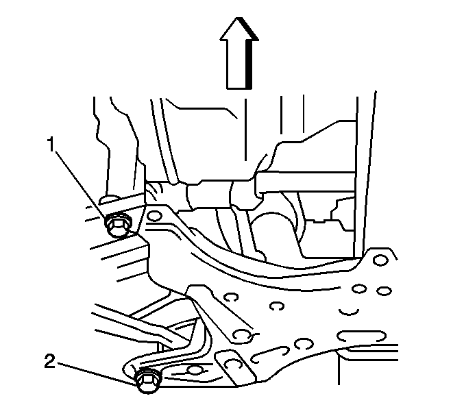
- Install the 2 bolts (1, 2) to the crossmember.
- Insert a wood dowel into the hole in the left side of the crossmember and the hole in the body.
- Use the dowel in order to align the bolt holes.
Note: DO NOT tighten the nut and bolts completely. The weight of the vehicle must be on the tire and wheel assemblies before tightening the nut and the bolts.

- Install the 2 bolts to the crossmember (3, 4).
- Insert a wood dowel into the hole in the right side of the crossmember and the hole in the body.
- Use the dowel in order to align the bolt holes.
Caution: Refer to Fastener Caution in the Preface section.
- Tighten the bolt (7) to
157 N·m (116 lb ft).
- Tighten the bolt (1) to
113 N·m (83 lb ft).
- Insert a wood dowel into the hole in the left side of the crossmember and the hole in the body.
- Use the dowel in order to align the bolt holes.
- Tighten the bolt (4) to
157 N·m (116 lb ft).
- Tighten the bolt (3) to
113 N·m (83 lb ft).
- Remove the jack from the crossmember.
- Install the 2 nuts (2, 5) and the bolt (6) and tighten the nuts and bolt to
52 N·m (38 lb ft).

- Install the following to the left front control arm:
| • | Tighten the 2 nuts and the bolt to
89 N·m (66 lb ft) |
- Install the following to the right front control arm:
| • | Tighten the 2 nuts and the bolt to
89 N·m (66 lb ft) |
- Install the left engine splash shield. Refer to
Engine Splash Shield Replacement - Left Side.
- Install the right engine splash shield. Refer to
Engine Splash Shield Replacement - Right Side.
- Install the front tire and wheel assemblies to the vehicle. Refer to
Tire and Wheel Removal and Installation.
- Lower the vehicle.
- Remove the engine support fixture.
- With the weight of the vehicle on the tire and wheel assemblies, push down on the front bumper 3 times in order to bounce the vehicle and stabilize the suspension.

- Tighten the nut (3) and the 2 bolts (1, 4) on the left lower control arm to
137 N·m (101 lb ft).
- Tighten the nut and the 2 bolts on the right lower control arm to
137 N·m (101 lb ft).
- Measure the wheel alignment. Adjust if necessary. Refer to
Wheel Alignment Measurement.
Front Suspension Crossmember Replacement Two Wheel Drive
Removal Procedure
-
Note: If you are removing the front suspension crossmember in order to gain access to other components, you may remove the following components together as a unit:
| • | The front suspension crossmember |
| • | The 2 lower control arms |
| • | The front stabilizer shaft |
| • | The steering gear, if necessary |
- Install the engine support fixture. Refer to
Engine Support Fixture or
Engine Support Fixture.
- Remove the steering gear. Refer to
Steering Gear Replacement.
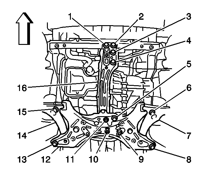
- Remove the 5 bolts (1, 2, 3, 4, 5).
- Remove the 3 nuts (9, 10, 11).
- Support the crossmember with a jack.
- Remove the 4 bolts (6, 8, 13, 15).
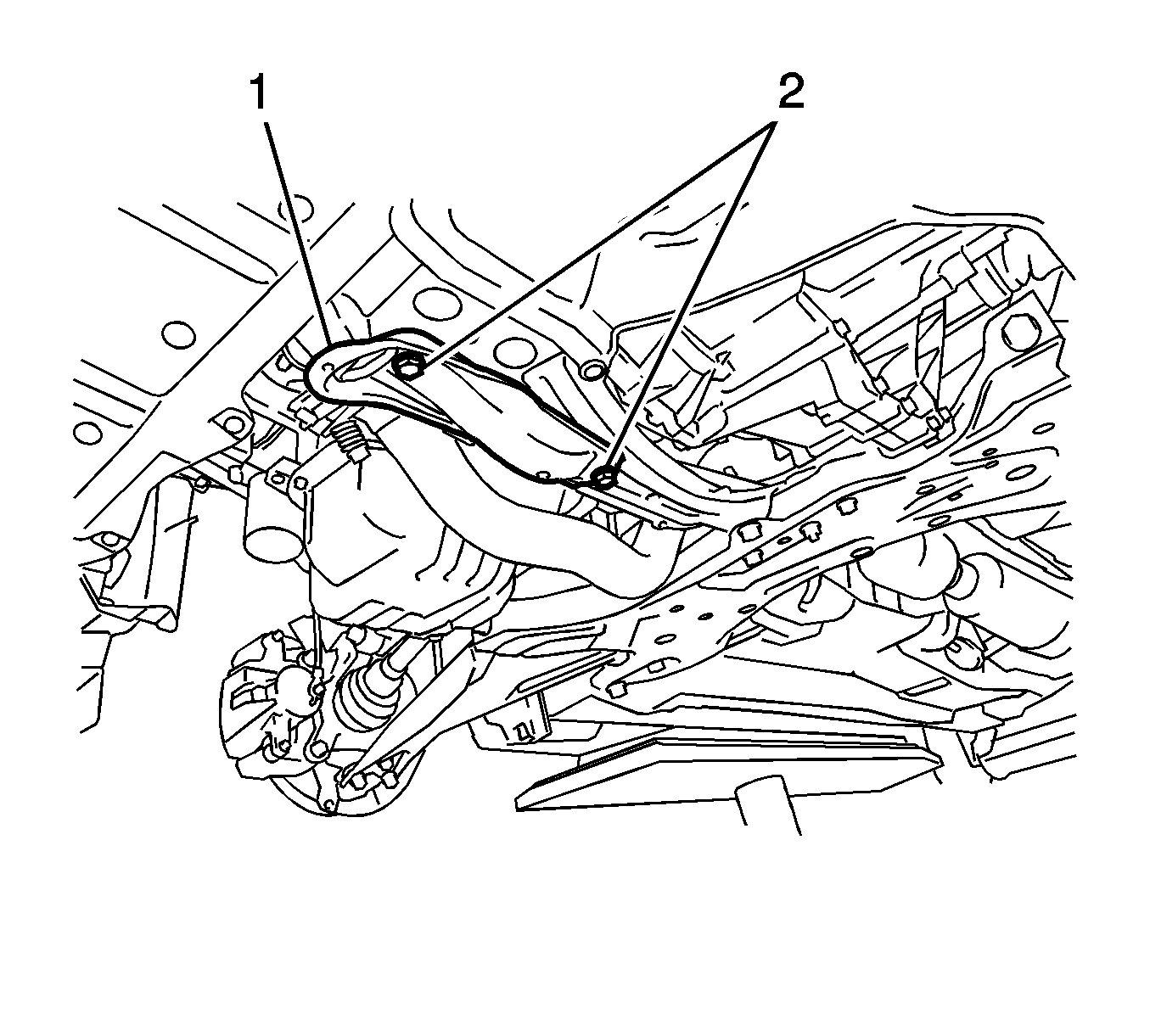
- Remove the two bolts (2).
- Remove the tow hook (1).
- Use the jack in order to lower the crossmember.
Note: If you are replacing the components on the crossmember, continue with this procedure.
- Remove the 2 bolts and the trans support from the crossmember.
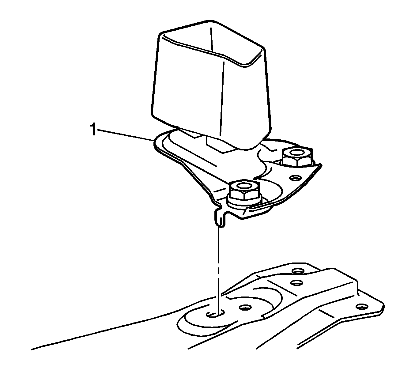
- Remove the front suspension dynamic damper (1).
- Remove the 2 control arms. Refer to
Lower Control Arm Replacement.
- Remove the following components from the crossmember. Refer to
Stabilizer Shaft Replacement.
| • | The 2 stabilizer shaft link nuts |
| • | The 2 stabilizer shaft links |
| • | The 4 stabilizer clamp bolts |
| • | The 2 stabilizer clamps |
| • | The 2 stabilizer shaft insulators |
Installation Procedure
- Install the following components to the crossmember. Refer to
Stabilizer Shaft Replacement.
| • | The 2 stabilizer shaft link nuts |
| • | The 2 stabilizer shaft links |
| • | The 4 stabilizer clamp bolts |
| • | The 2 stabilizer clamps |
| • | The 2 stabilizer shaft insulators |
- Install the steering gear. Refer to
Steering Gear Replacement.

Note: DO NOT tighten the nut and bolts completely. The weight of the vehicle must be on the tire and wheel assemblies before tightening the nut and the bolts.
- Install the following components to the crossmember:
| • | The left lower control arm (2) |
Note: DO NOT tighten the nut and bolts completely. The weight of the vehicle must be on the tire and wheel assemblies before tightening the nut and the bolts.
- Install the following components to the crossmember:
| • | The right lower control arm |
Note: DO NOT tighten the nut and bolts completely. The weight of the vehicle must be on the tire and wheel assemblies before tightening the nut and the bolts.
- Install the trans support and the 2 bolts to the crossmember.
- Use a jack in order to raise and support the crossmember with the attached components as a unit.

- Install the front suspension dynamic damper (1).

- Insert a wood dowel (1) into the hole in the right side of the crossmember (3) and the hole in the body.
- Use the dowel in order to align the bolt holes.

- Install the 2 bolts (1, 2) to the crossmember.
- Insert the dowel into the hole in the left side of the crossmember and the hole in the body.
- Use the dowel in order to align the bolt holes.

- Install the 2 bolts to the crossmember (8, 6).
- Insert the dowel into the hole in the right side of the crossmember and the hole in the body.
- Use the dowel in order to align the bolt holes.
Caution: Refer to Fastener Caution in the Preface section.
- Install the bolt (13) and tighten to
157 N·m (116 lb ft).
- Install the bolt (15) and tighten to
113 N·m (83 lb ft).
- Insert the dowel into the hole in the left side of the crossmember and the hole in the body.
- Use the dowel in order to align the bolt holes.
- Install the bolt (8) and tighten to
157 N·m (116 lb ft).
- Install the bolt (6) and tighten to
113 N·m (83 lb ft).
- Remove the jack from the crossmember.
- Install the 3 nuts (9, 10, 11) and tighten to
52 N·m (38 lb ft).
- Install the bolts (1, 2) and tighten to
60 N·m (40 lb ft).
- Install the bolts (3, 4, 5) and tighten to
81 N·m (60 lb ft).

- Install the tow hook (1).
- Install the bolts (2) and tighten to
39 N·m (29 lb ft).
- Install the front tire and wheel assemblies to the vehicle. Refer to
Tire and Wheel Removal and Installation.
- Lower the vehicle.
- Remove the engine support fixture.
- With the weight of the vehicle on the tire and wheel assemblies, push down on the front bumper 3 times in order to bounce the vehicle and stabilize the suspension.

- Install the nut (3) and the 2 bolts (1, 4) on the left lower control arm, and
tighten to
137 N·m (100 lb ft).
- Install the nut and the 2 bolts on the right lower control arm, and tighten to
137 N·m (100 lb ft).
- Measure the wheel alignment. Adjust if necessary. Refer to
Wheel Alignment Measurement.


