Steering Gear Replacement Front Wheel Drive
Special Tools
| • | CH-49200 Steering Gear Support |
| • | J-6627-A Tie Rod Puller |
Removal Procedure
- LOCK the steering column with the front wheels in the straight ahead position.
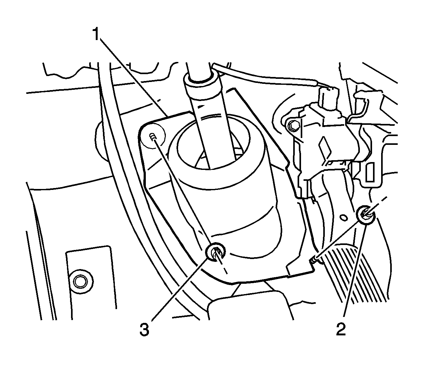
- Turn back the floor carpet and remove the 2 clips (2, 3).
- Remove the column hole cover silencer sheet (1).
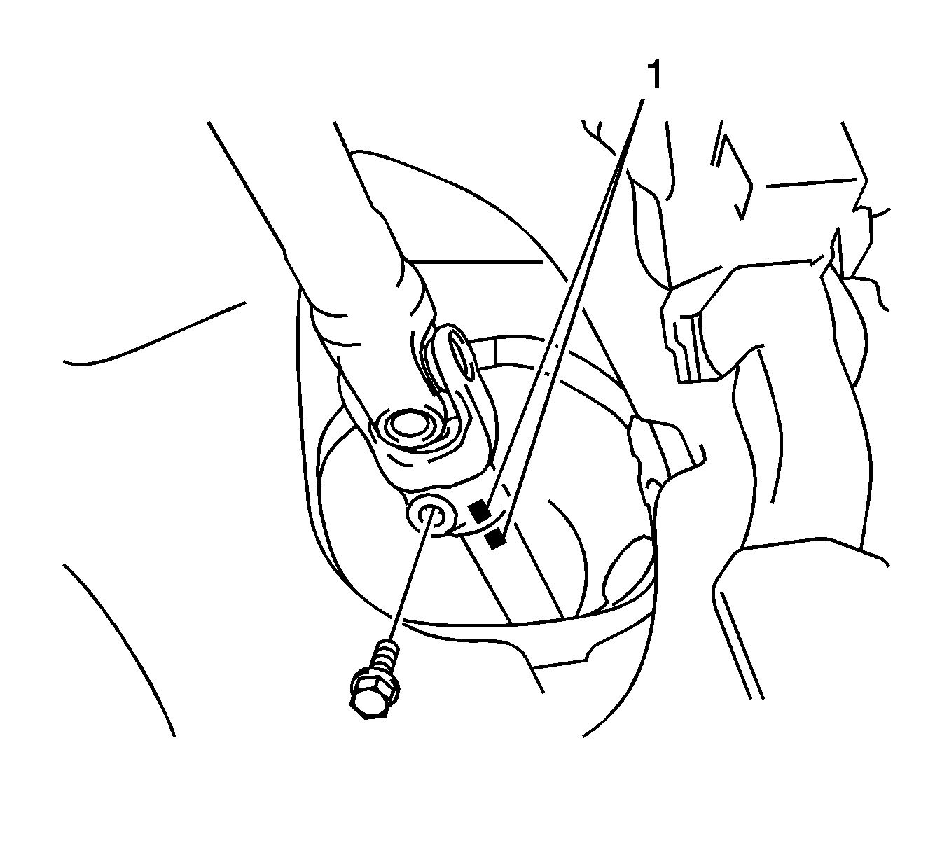
- Place match marks (1) on the upper intermediate shaft and on the lower intermediate shaft.
- Remove the bolt.
- Separate the upper intermediate shaft from the lower intermediate shaft.
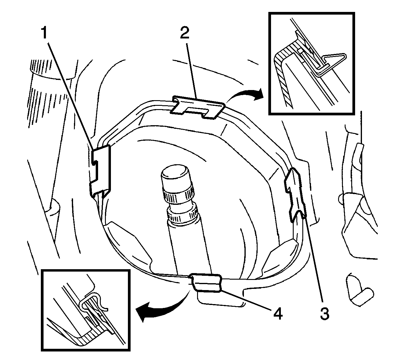
- Remove 3 clips (1, 2, 3).
- Remove the steering column hole cover and disengage clip (4) from the body.
- Raise and support the vehicle. Refer to Lifting and Jacking the Vehicle.
- Remove the front tire and wheel assemblies. Refer to Tire and Wheel Removal and Installation.
- Remove the left side engine splash shield. Refer to Engine Splash Shield Replacement - Left Side.
- Remove the right side engine splash shield. Refer to Engine Splash Shield Replacement - Right Side.
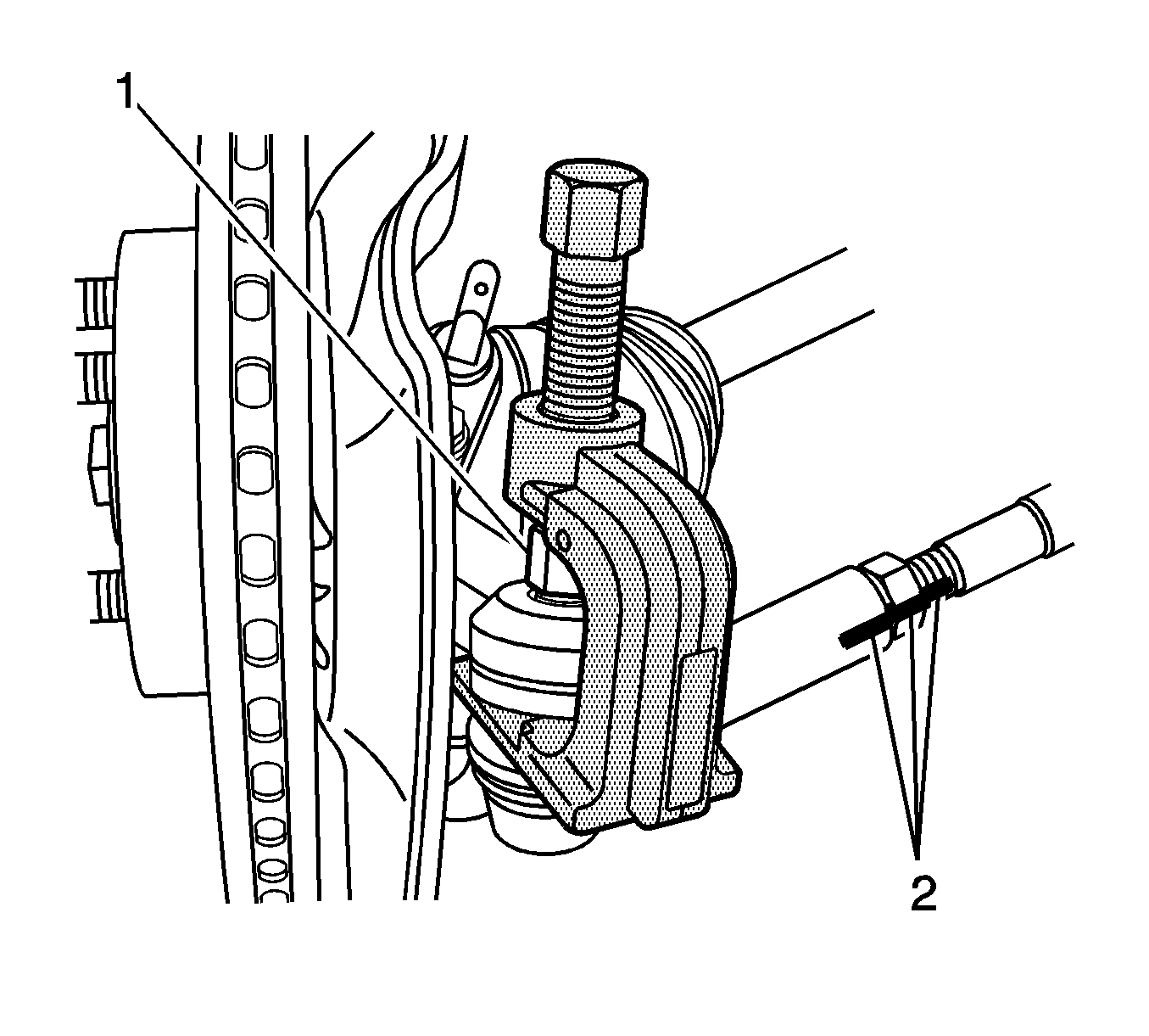
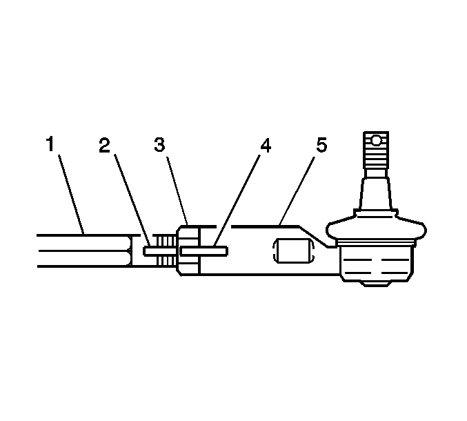
- Use paint in order to place match marks (2) on the tie rod ends and on the inner tie rods.
- Remove the cotter pin from the left side tie rod end ball stud.
- Loosen the left side tie rod end nut (1).
- Use the J-6627-A puller , or equivalent, in order to separate the left side tie rod end from the knuckle.
- Remove the left side tie rod nut.
- Remove the cotter pin from the right side tie rod end ball stud.
- Loosen the right side tie rod nut.
- Use the J-6627-A puller , or equivalent, in order to separate the right side tie rod end from the knuckle.
- Remove the right side tie rod nut.
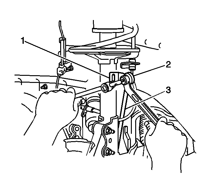
- Use a wrench in order to hold the left front stabilizer shaft link stud. Remove the nut from the stud and separate the link (3) from the left front strut bracket (1).
- Use a wrench in order to hold the right front stabilizer shaft link stud. Remove the nut from the stud and separate the link from the right front strut.
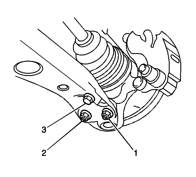
- Remove the bolt (3) and the 2 nuts (1, 2) from the left front control arm.
- Remove the bolt and the 2 nuts from the right front control arm.
- Lower the front suspension crossmember as much as necessary in order to access the steering gear. Refer to Front Suspension Crossmember Replacement.
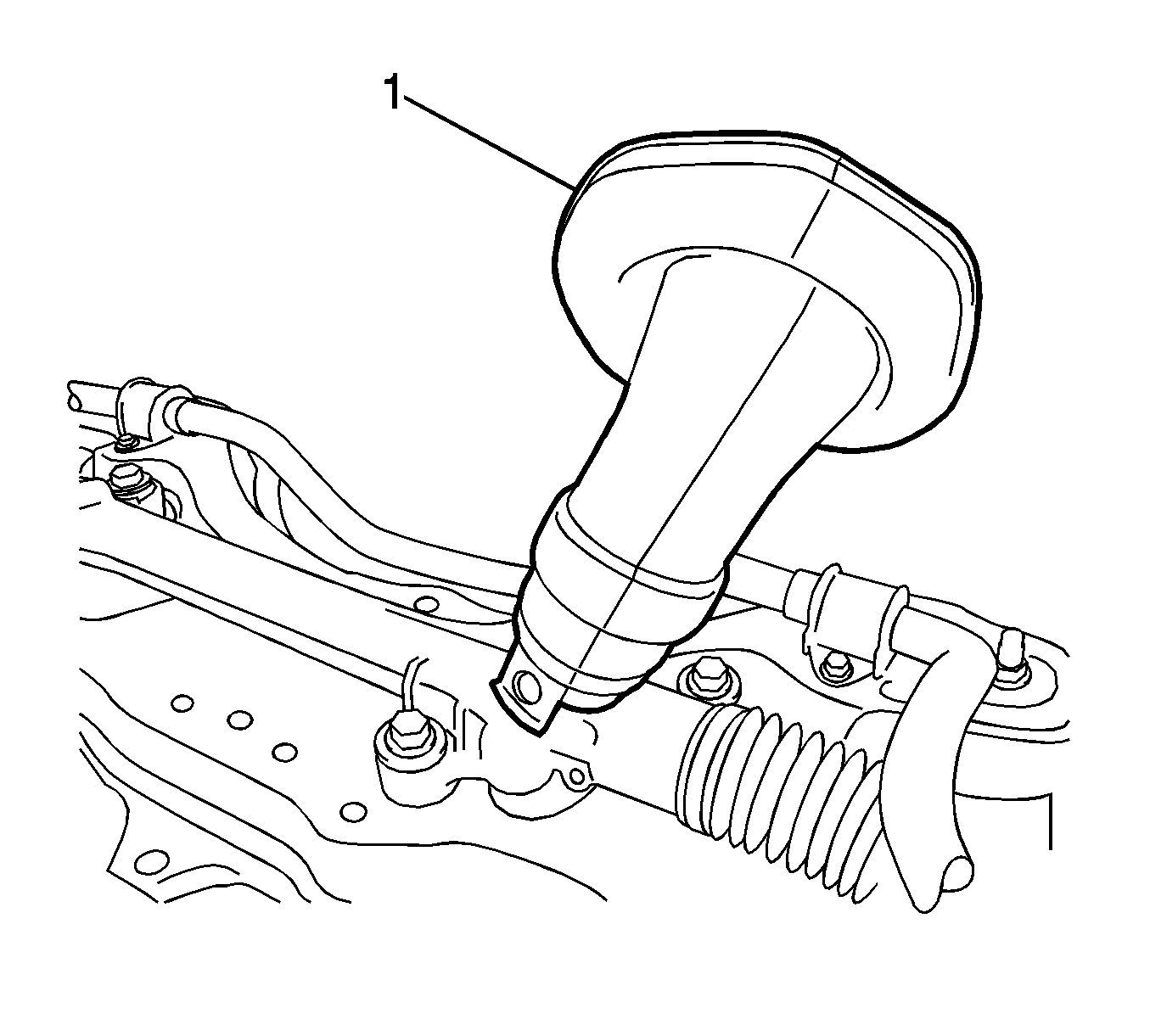
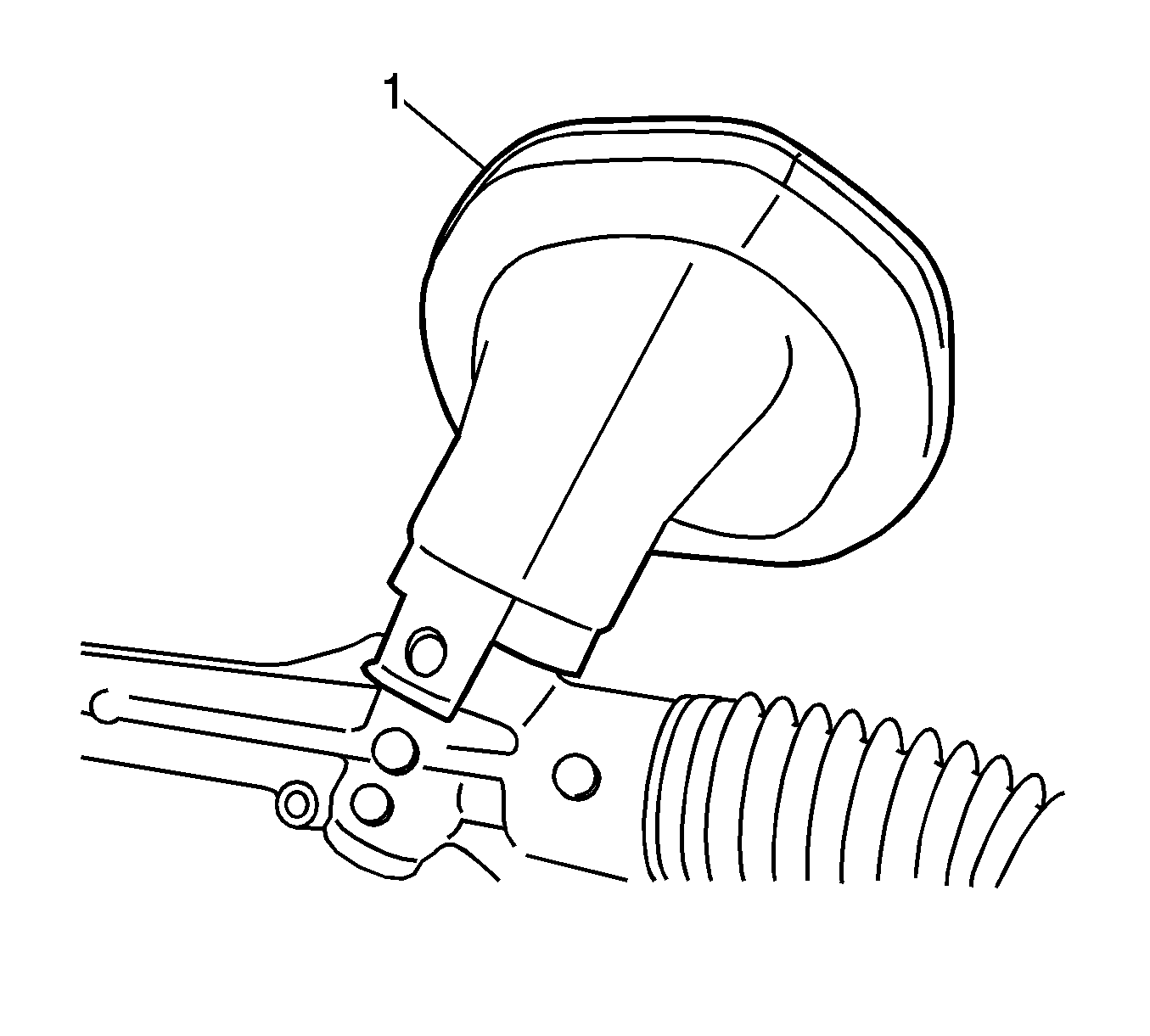
- Remove the steering column hole cover (1) from the steering gear.
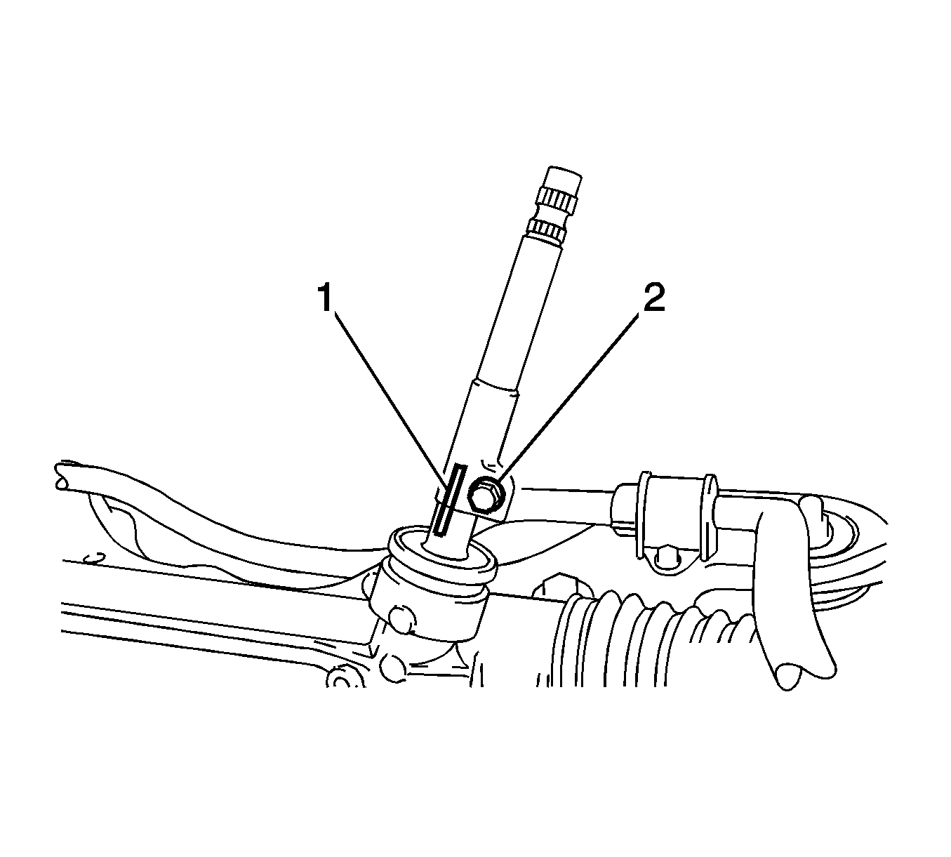
- Put match marks (1) on the lower intermediate shaft and on the steering gear pinion shaft.
- Remove the bolt (2) and the lower intermediate shaft from the steering gear.
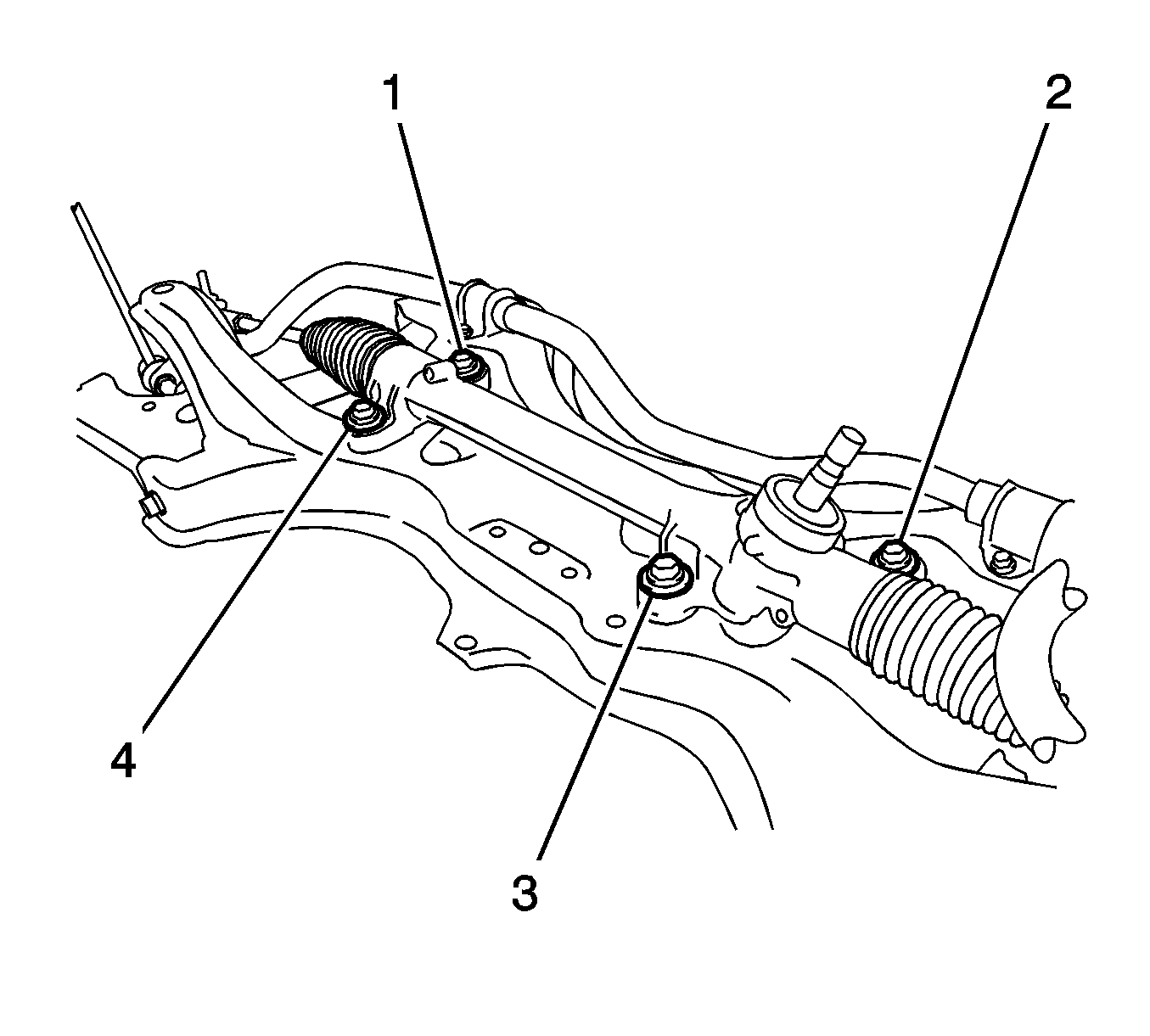
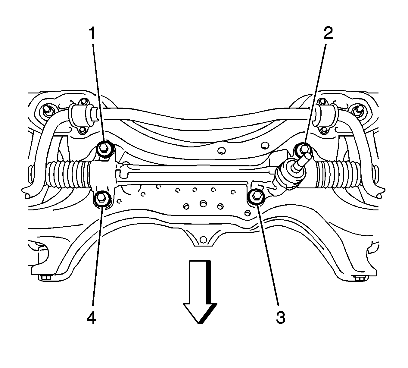
- Remove the 4 bolts (1, 2, 3, 4) and the steering gear from the front suspension crossmember.
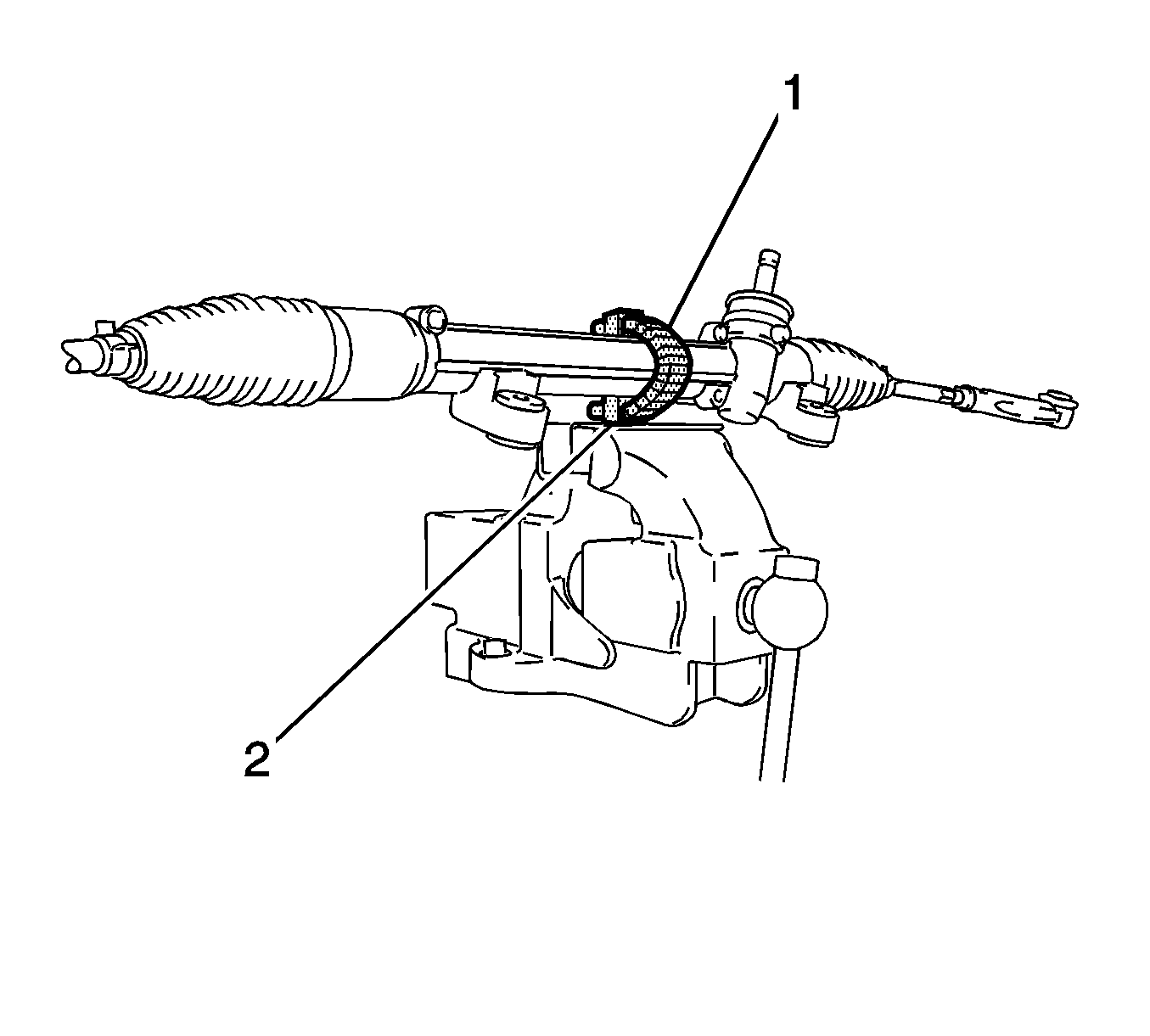
- Wrap tape (1) around the CH-49200 support (2).
- Use the CH-49200 support and a vise in order to hold the steering gear.
- Loosen the lock nuts (3).
- Remove the tie rod ends.
- Remove the lock nuts.
Caution: Refer to Steering Column in Lock Position Caution in the Preface section.
Inspection Procedure
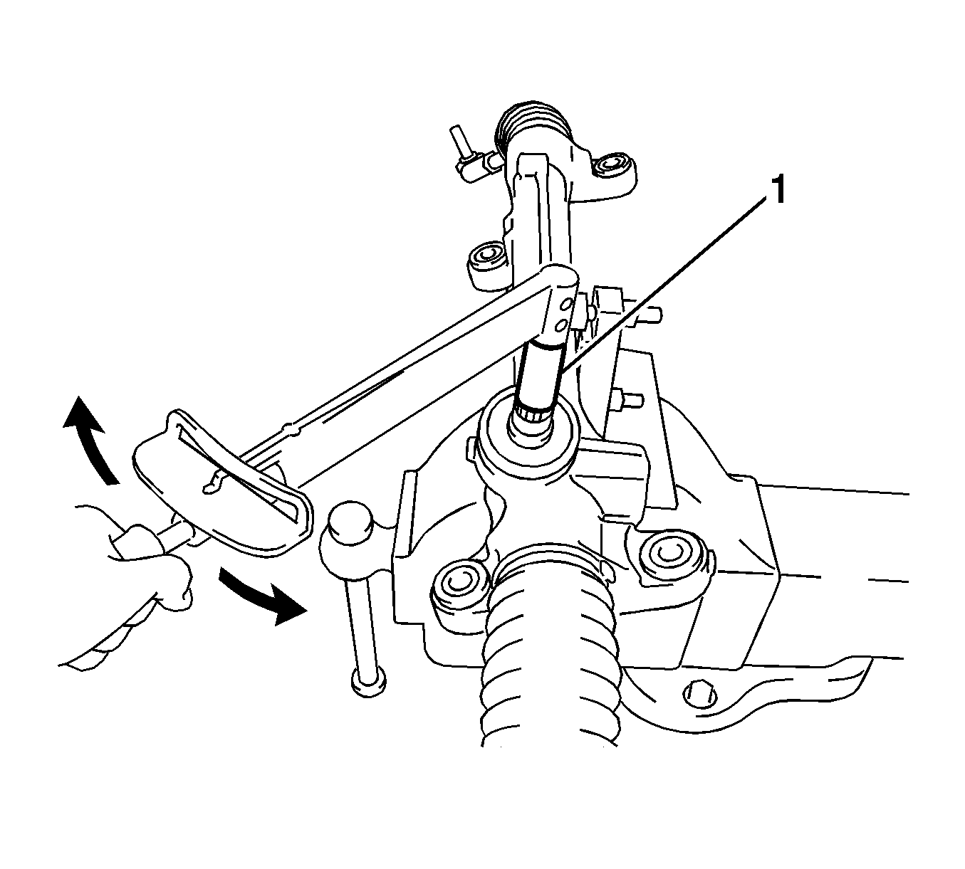
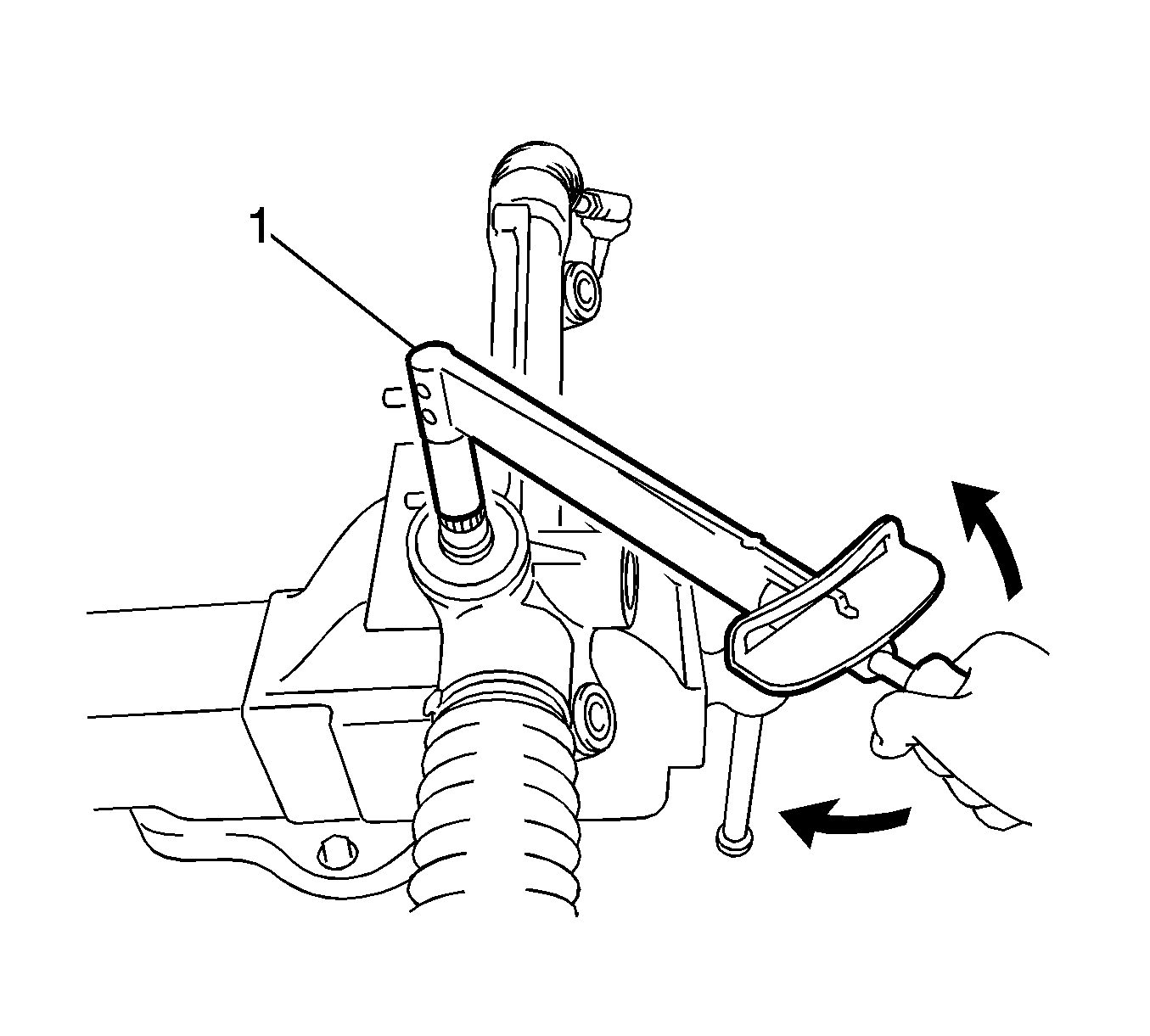
- Using a torque wrench and a socket (1), inspect the total preload around the steering rack center position. If the total preload is not within the specified range, replace the steering gear.
- Inspect the ball joint seal on each of the tie rod ends. If the seal is damaged or not holding the lubricant, replace the damaged tie rod end.
- Clamp each of the tie rod ends in a soft-jawed vise.
- Install a nut to the stud.
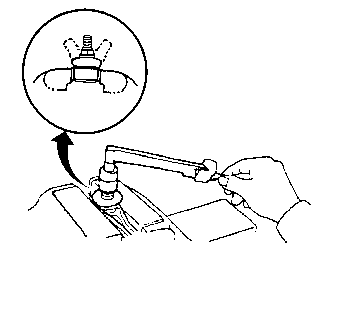
- Move the ball joint back and forth 5 times.
- Use a beam type torque wrench and a socket on the nut in order to turn the ball joint continuously at a rate of 2 to 4 seconds per turn.
- Measure the turning torque on the 5th turn. If the turning torque is not within the specified range, replace the tie rod end.
- Inspect the steering column hole cover (1) for damage. If the cover is damaged, replace the cover.
Specification
The standard preload is 0.7 to 1.1 N·m (7 to 9 lb in).
Specification
The standard turning torque is 0.3 to 1.9 N·m (3 to 17 lb in).
Installation Procedure
- Install, but do not tighten, the lock nuts (3) and the tie rod ends (5) to the inner tie rods (1). Align the match marks (2, 4).
- Install the steering gear to the front suspension crossmember sub-assembly with the 4 bolts.
- Tighten the right front bolt (4) to 58 N·m (43 lb ft).
- Tighten the left front bolt (3) to 58 N·m (43 lb ft).
- Tighten the left rear bolt (2) to 58 N·m (43 lb ft).
- Tighten the right rear bolt (1) to 58 N·m (43 lb ft).
- Align the match marks (1) and install the lower intermediate shaft to the steering gear pinion shaft.
- Install the bolt (2) and tighten to 35 N·m (26 lb ft).
- Align the round hole in the steering column hole cover (1) with the protrusion on the steering gear. Install the cover.
- Install the front suspension crossmember. Refer to Front Suspension Crossmember Replacement.
- Install the 2 nuts (1, 2) and the bolt (3) to the left front control arm and tighten to 89 N·m (66 lb ft).
- Install the 2 nuts and the bolt to the right front control arm and tighten to 89 N·m (66 lb ft).
- Use a wrench in order to hold the left front stabilizer shaft link stud. Install the nut and the stud to the strut bracket (1). Tighten the nut to 74 N·m (55 lb ft).
- Use a wrench in order hold the right front stabilizer shaft link stud. Install the nut and the stud to the strut bracket. Tighten the nut to 74 N·m (55 lb ft).
- Connect the tie rod ends to the steering knuckles with the nuts (1). Tighten the nuts to 49 N·m (36 lb ft).
- Install 2 NEW cotter pins.
- Engage the clip (4) onto the body and install the steering column hole cover onto the body.
- Install the 3 clips (1, 2, 3).
- Align the match marks (1) and install the upper intermediate shaft to the lower intermediate shaft.
- Install the bolt and tighten to 35 N·m (26 lb ft).
- Ensure the front wheels are in the straight ahead position.
- Install the column hole cover silencer sheet (1) with the 2 clips (2, 3).
- Install the floor carpet.
- Install the right side engine splash shield. Refer to Engine Splash Shield Replacement - Right Side.
- Install the left side engine splash shield. Refer to Engine Splash Shield Replacement - Left Side.
- Install the front tire and wheel assemblies. Refer to Tire and Wheel Removal and Installation.
- Measure the wheel alignment. Refer to Wheel Alignment Measurement.
- Adjust the front toe and tighten the tie rod end lock nuts. Refer to Front Toe Adjustment.
- Lower the vehicle.

Caution: Refer to Fastener Caution in the Preface section.


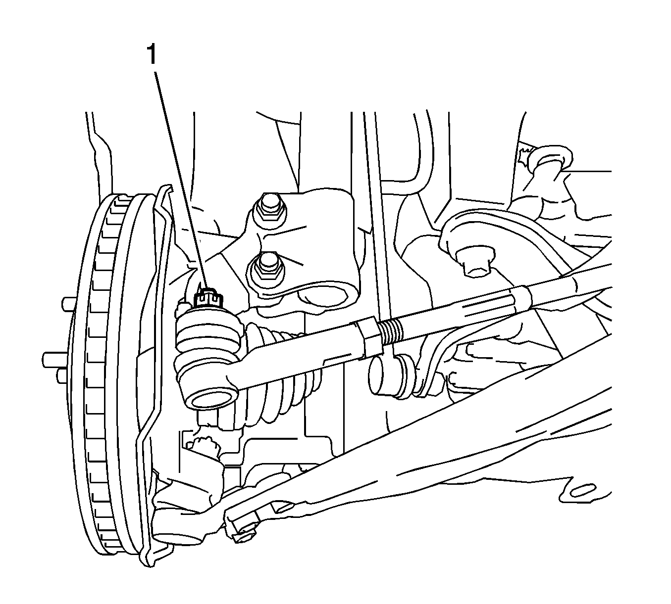
If the nut does not align with the hole for the cotter pin, tighten the nut up to an additional 60 degrees.


Steering Gear Replacement All Wheel Drive
Special Tools
| • | CH-49200 Steering Gear Support |
| • | J-6627-A Tie Rod Puller |
Removal Procedure
- LOCK the steering column with the front wheels in the straight ahead position.
- Turn back the floor carpet and remove the 2 clips (2, 3).
- Remove the column hole cover silencer sheet (1).
- Place match marks (1) on the intermediate shaft assembly and on the steering gear pinion shaft.
- Remove the bolt from the intermediate shaft.
- Separate the intermediate shaft assembly from the steering gear pinion shaft.
- Remove 3 clips (1, 2, 3).
- Remove the steering column hole cover and disengage clip (4) from the body.
- Raise and support the vehicle. Refer to Lifting and Jacking the Vehicle.
- Remove the front tire and wheel assemblies. Refer to Tire and Wheel Removal and Installation.
- Remove the left side engine splash shield. Refer to Engine Splash Shield Replacement - Left Side.
- Remove the right side engine splash shield. Refer to Engine Splash Shield Replacement - Right Side.
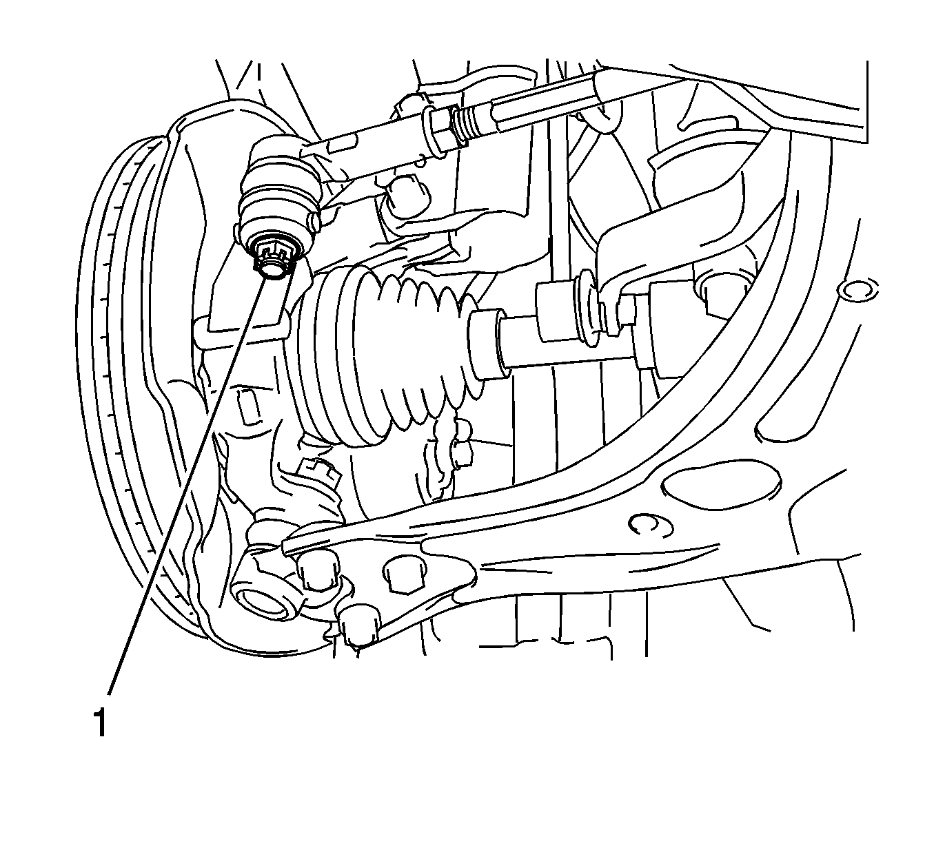
- Remove the cotter pin and the nut (1) from the left side tie rod end.
- Use the J-6627-A puller , or equivalent, in order to separate the left side tie rod end from the knuckle.
- Install, but do not tighten, the nut in order to loosely hold the left tie rod end to the knuckle.
- Remove the cotter pin and the nut from the right side tie rod end.
- Use the J-6627-A puller , or equivalent, in order to separate the right side tie rod end from the knuckle.
- Install, but do not tighten, the nut in order to loosely hold the right tie rod end to the knuckle.
- Remove the bolt (3) and the 2 nuts (1, 2) from the left front control arm.
- Remove the bolt and the 2 nuts from the right front control arm.
- Use wire in order to secure the steering gear to the transfer case.
- Lower the front suspension crossmember as much as necessary in order to access the steering gear. Refer to Front Suspension Crossmember Replacement.
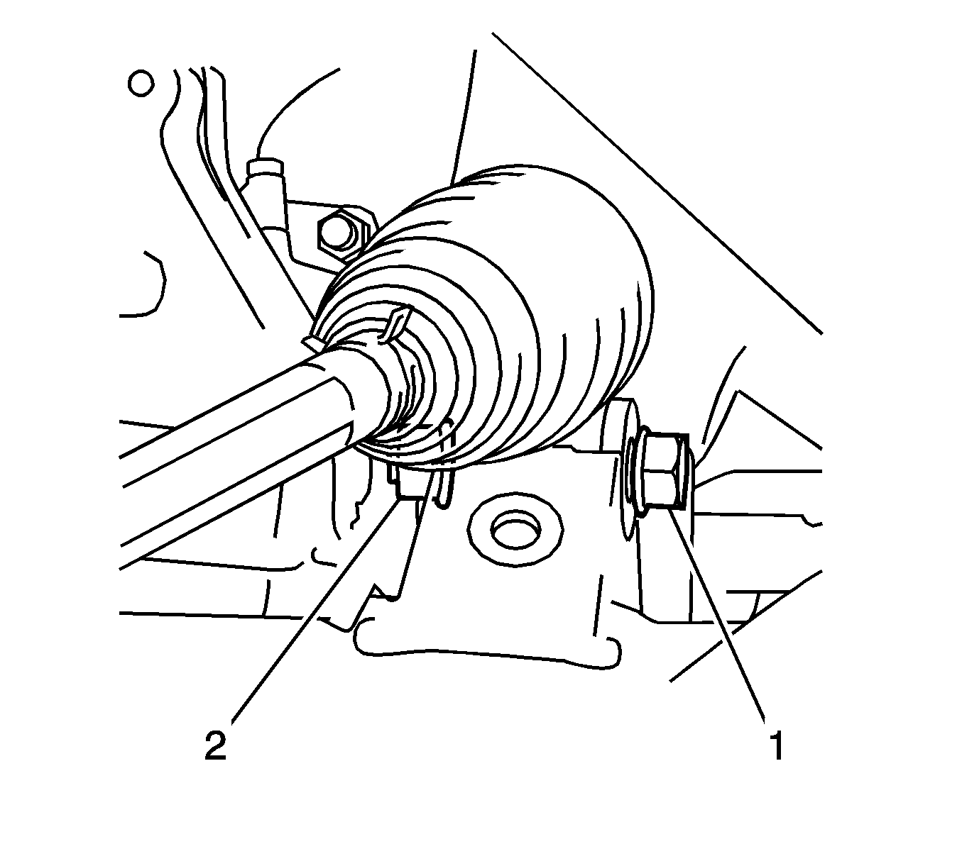
- On the left side, hold the nut (2) and remove the bolt (1) from the steering gear.
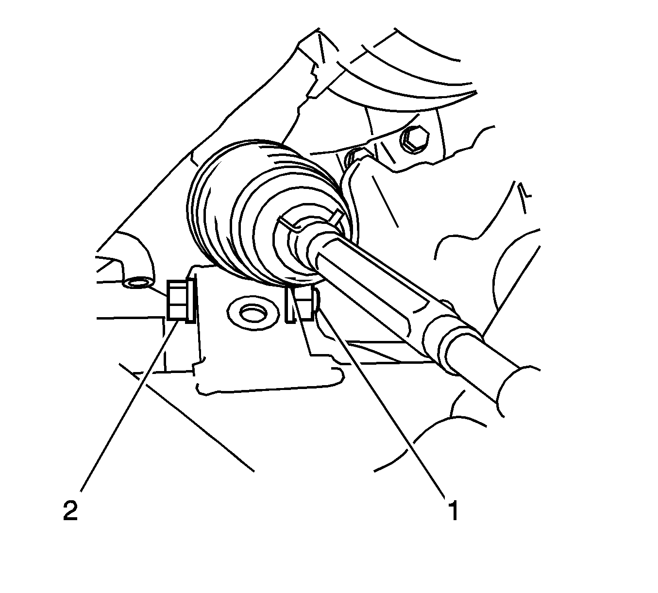
- On the right side, hold the nut (1) and remove the bolt (2) from the steering gear.
- Remove the 4 bolts from the stabilizer shaft insulator clamps.
- Remove the 2 nuts from the 2 outer tie rod ends.
- Remove the wire and the steering gear from the crossmember.
- Remove the steering column hole cover (1) from the steering gear.
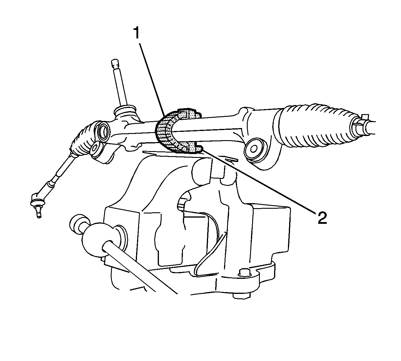
- Wrap tape (1) around the CH-49200 support (2).
- Use the CH-49200 support and a vise in order to hold the steering gear.
- Use paint in order to place match marks (2, 4) on the tie rod ends (5) and on the inner tie rods (1).
- Remove the tie rod ends and the lock nuts (3).
Caution: Refer to Steering Column in Lock Position Caution in the Preface section.





Inspection Procedure
- Using a torque wrench (1) and a socket, inspect the total preload around the steering rack center position. If the total preload is not within the specified range, replace the steering gear.
- Inspect the ball joint seal on each of the tie rod ends. If the seal is damaged or not holding the lubricant, replace the damaged tie rod end.
- Clamp each of the tie rod ends in a soft-jawed vise.
- Install a nut to the stud.
- Move the ball joint back and forth 5 times.
- Use a beam type torque wrench and a socket on the nut in order to turn the ball joint continuously at a rate of 2 to 4 seconds per turn.
- Measure the turning torque on the 5th turn. If the turning torque is not within the specified range, replace the tie rod end.
- Inspect the steering column hole cover (1) for damage. If the cover is damaged, replace the cover.
Specification
The standard preload is 0.7 to 1.1 N·m (7 to 9 lb in).

Specification
The standard turning torque is 0.3 to 1.9 N·m (3 to 17 lb in).

Installation Procedure
- Install, but do not tighten, the lock nuts (3) and the tie rod ends (5) to the inner tie rods (1). Align the match marks (2, 4).
- Align the round hole in the steering column hole cover (1) with the protrusion on the steering gear. Install the cover.
- Position the steering gear near the transfer case. Use wire in order to secure the steering gear to the transfer case.
- Position the tie rod ends on the knuckles. Install, but do not tighten, the nuts in order to loosely hold the tie rod ends to the knuckles.
- Raise and support the front suspension crossmember close to the steering gear.
- Install the stabilizer shaft insulator brackets.
- Install the 4 bolts to the brackets and tighten to 24 N·m (18 lb ft).
- On the left side, install the bolt (1) and the nut (2) in order to retain the steering gear to the crossmember. Hold the nut and tighten the bolt to 82 N·m (60 lb ft).
- On the right side, install the bolt (2) and the nut (1) in order to retain the steering gear to the crossmember. Hold the nut and tighten the bolt to 82 N·m (60 lb ft).
- Install the front suspension crossmember. Refer to Front Suspension Crossmember Replacement.
- Remove the wire supporting the steering gear.
- Install the 2 nuts (1, 2) and the bolt (3) to the left front control arm and tighten to 89 N·m (66 lb ft).
- Install the 2 nuts and the bolt to the right front control arm and tighten to 89 N·m (66 lb ft).
- Tighten the 2 tie rod end nuts (1) to 49 N·m (36 lb ft).
- Install 2 NEW cotter pins.
- Engage the clip (4) onto the body and install the steering column hole cover onto the body.
- Install the 3 clips (1, 2, 3).
- Align the match marks (1) and install the intermediate shaft to the steering gear pinion shaft.
- Install the bolt and tighten to 35 N·m (26 lb ft).
- Ensure the front wheels are in the straight ahead position.
- Install the column hole cover silencer sheet (1) with the 2 clips (2, 3).
- Install the floor carpet.
- Install the right side engine splash shield. Refer to Engine Splash Shield Replacement - Right Side.
- Install the left side engine splash shield. Refer to Engine Splash Shield Replacement - Left Side.
- Install the front tire and wheel assemblies. Refer to Tire and Wheel Removal and Installation.
- Measure the wheel alignment. Refer to Wheel Alignment Measurement.
- Adjust the front toe and tighten the tie rod end lock nuts. Refer to Front Toe Adjustment.
- Lower the vehicle.


Caution: Refer to Fastener Caution in the Preface section.


If the nut does not align with the hole for the cotter pin, tighten the nut up to an additional 60 degrees.


