For 1990-2009 cars only
Removal Procedure
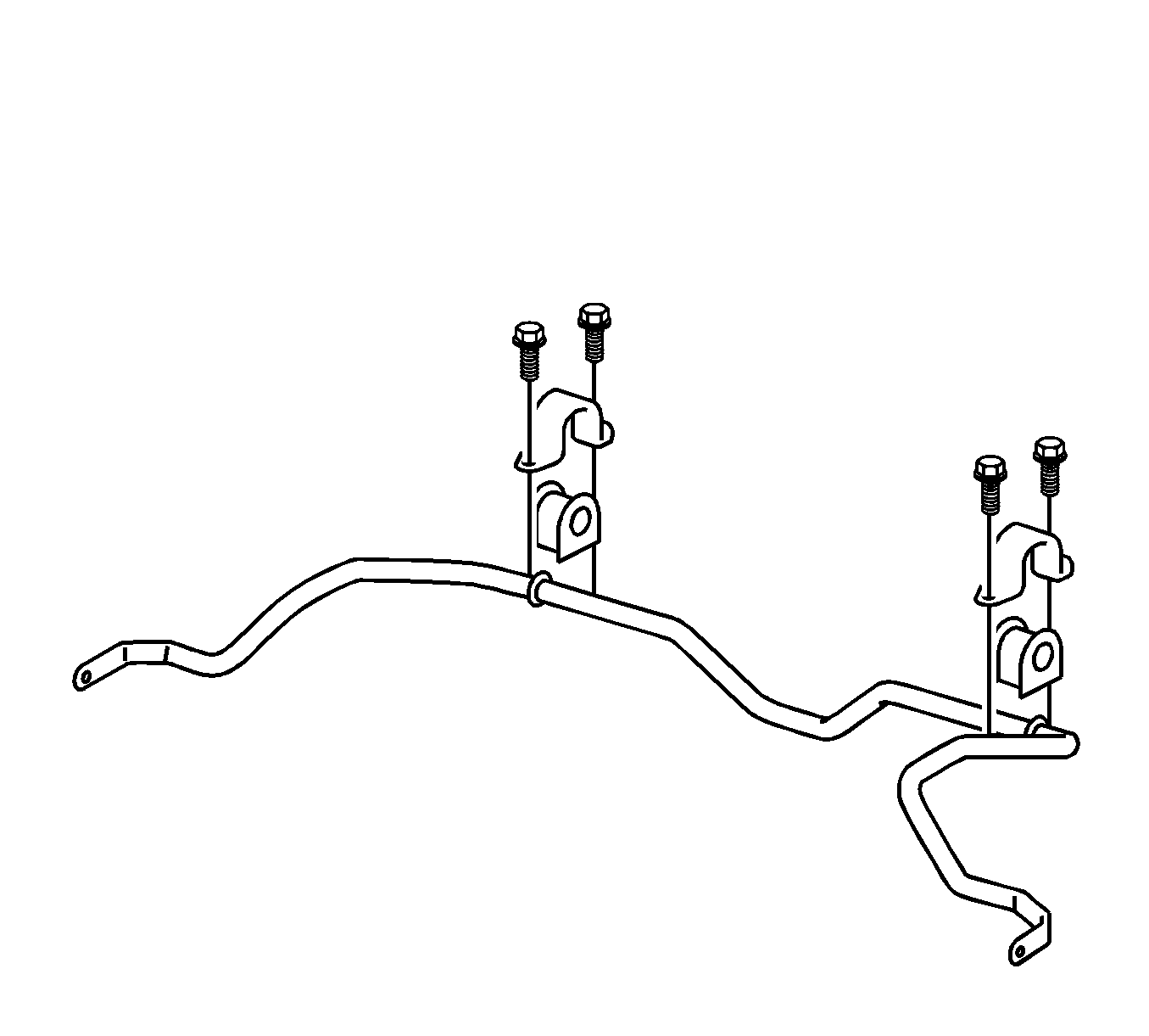
- Lower the following components as an assembly as far as necessary in order to access the stabilizer shaft. Refer to Front Suspension Crossmember Replacement.
- Use a 6 mm wrench in order to hold each stabilizer shaft lower link stud. Remove the 2 nuts and the 2 stabilizer shaft links from the stabilizer shaft.
- Remove the 4 bolts from the stabilizer shaft clamps.
- Remove the 2 stabilizer shaft clamps.
- Remove the 2 stabilizer shaft insulators.
- Remove the stabilizer shaft from the crossmember.
| • | The front suspension crossmember |
| • | The trans support |
| • | The front control arms |
| • | The stabilizer shaft |
| • | The stabilizer shaft links |
| • | The stabilizer shaft clamps |
| • | The stabilizer shaft insulators |

Installation Procedure
- Position the stabilizer shaft on the crossmember.
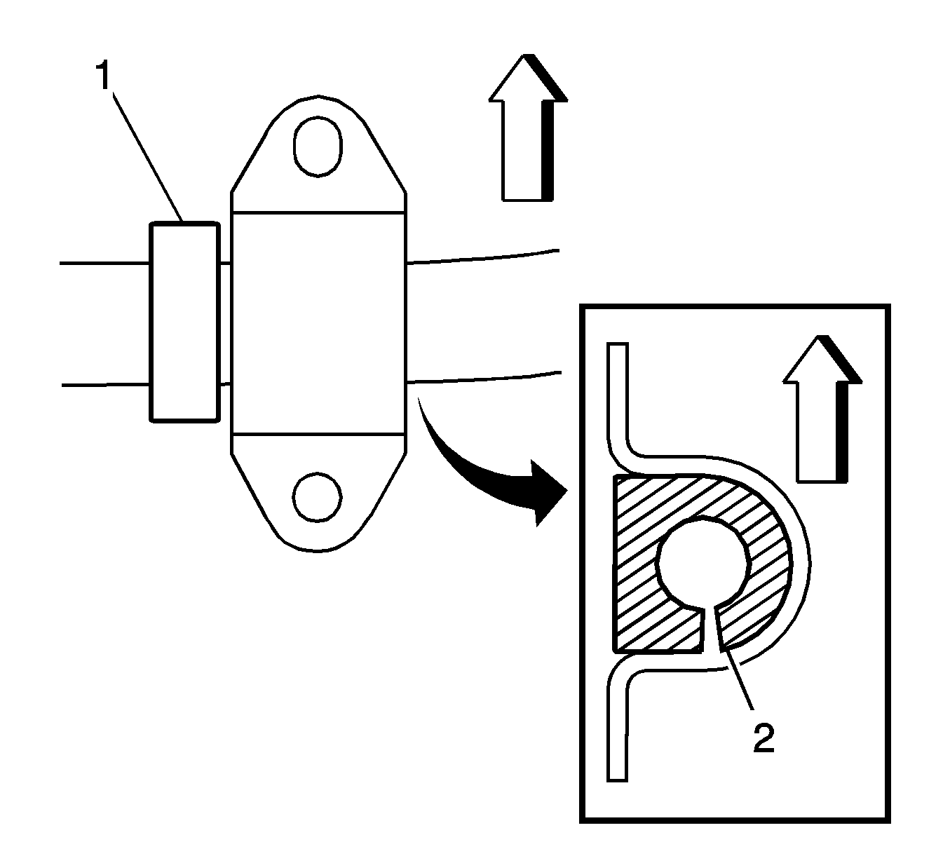
- Install the 2 stabilizer shaft insulators to the outer side of the rings (1) on the stabilizer shaft. Position the cutout (2) in the insulator toward the rear of the vehicle.
- Install the 2 clamps to the insulators.
- Install the 4 bolts to the clamps. Tighten the bolts to 24 N·m (18 lb ft).
- Use a 6 mm wrench in order to hold each stabilizer shaft link lower stud. Install the 2 stabilizer shaft links and the 2 nuts to the stabilizer shaft. Tighten the nuts to 74 N·m (55 lb ft).
- Install the stabilizer shaft and the crossmember to the vehicle. Refer to Front Suspension Crossmember Replacement.

Caution: Refer to Fastener Caution in the Preface section.

