Removal Procedure
- Remove the right engine under cover.
- Remove the engine cover sub-assembly. Refer to
Engine Cover Replacement.
- Remove the ignition coil assembly. Refer to
Spark Plug Replacement.
- Remove the spark plug. Refer to
Spark Plug Replacement.
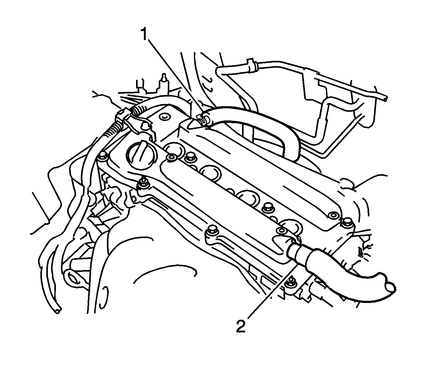
- Remove the 2 ventilation hoses (1, 2) from the cylinder head cover.
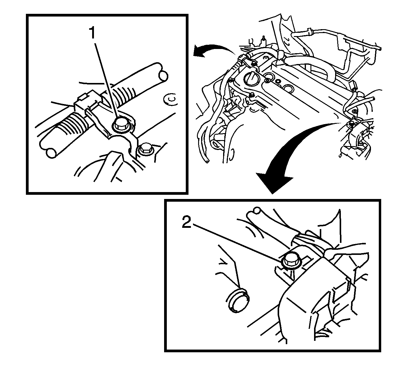
- Remove the 2 bolts (1, 2) and separate the 2 wire harness brackets.
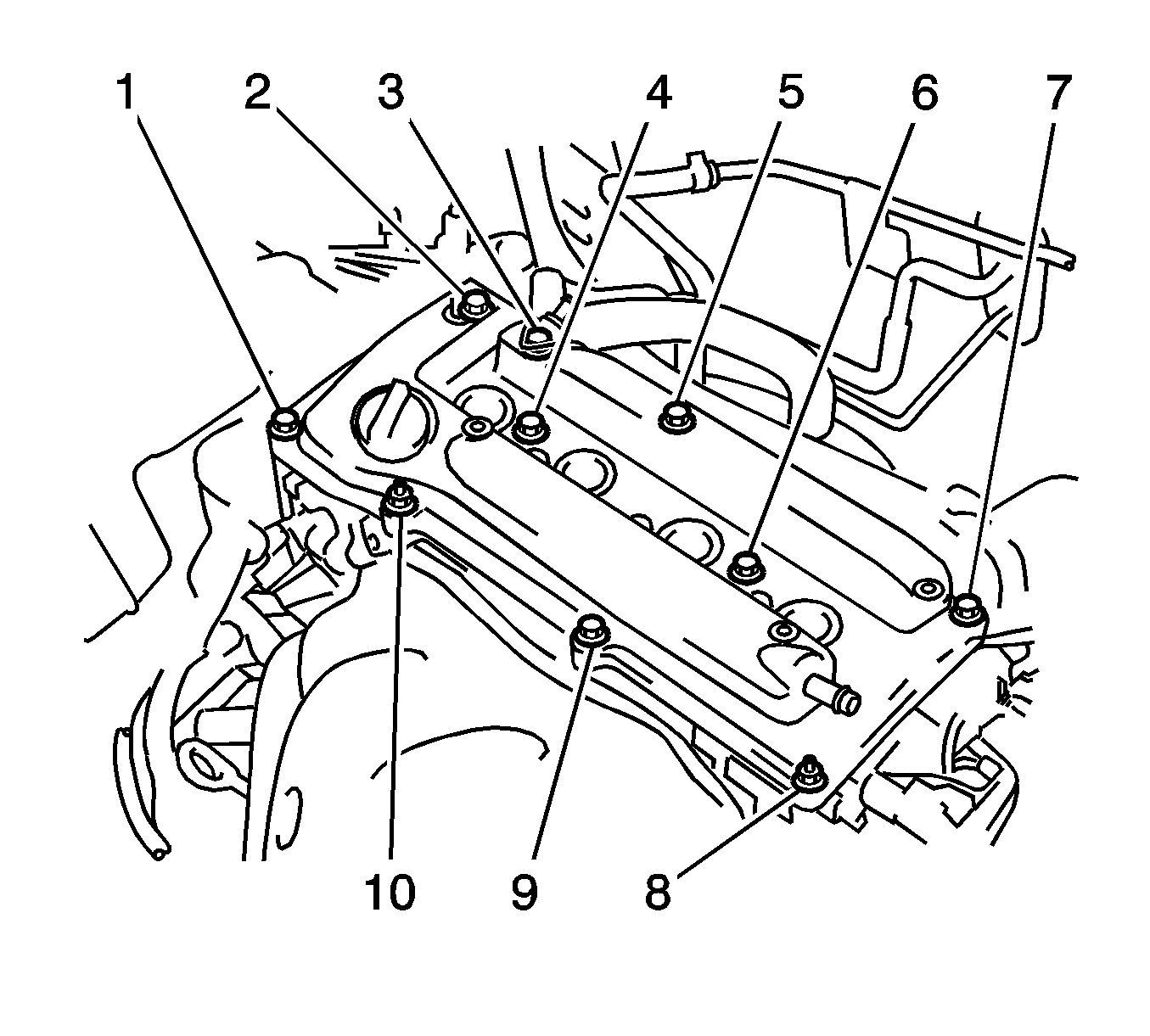
- Remove the 8 bolts (1-7, 9), and 2 nuts (8, 10), then remove the cylinder head cover sub-assembly and gasket.
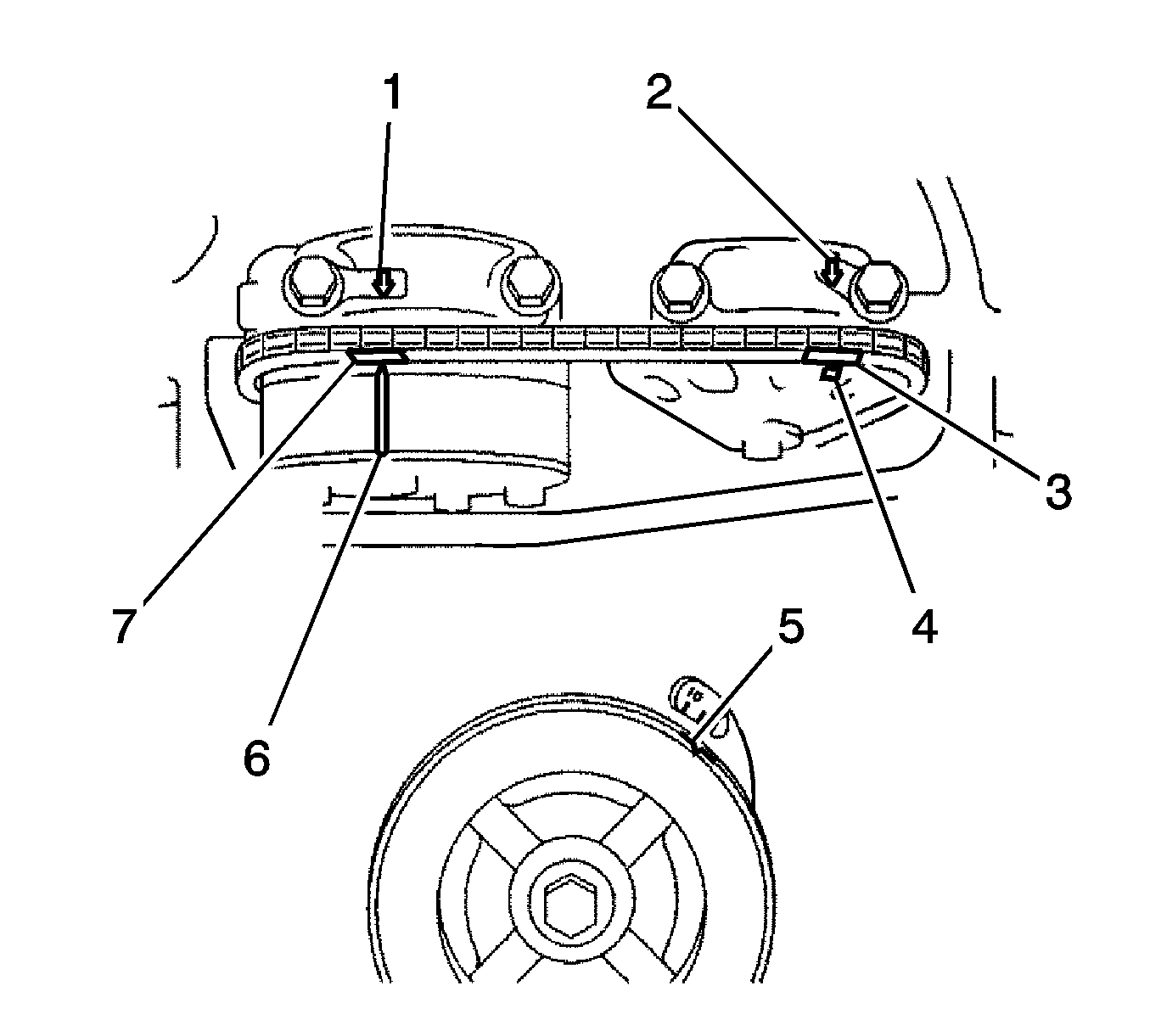
- Set No. 1 cylinder to TDC/compression by turning the crankshaft pulley until the groove and the timing mark "0" (5) on the timing chain cover
are aligned.
- Check that each timing mark on the camshaft timing gear (4, 6) and sprocket is aligned with each timing mark located on the intake and exhaust bearing caps, as shown in the illustration.
- If not, turn the crankshaft pulley by 1 revolution (360°) to align the timing marks as illustrated.
- Place paint marks (3, 7) on the chain in alignment with the timing marks on the camshaft timing gear and camshaft timing sprocket.
- Remove the chain tensioner assembly.
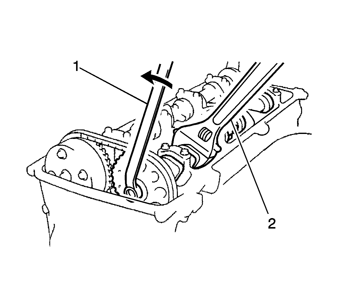
- Loosen the camshaft timing gear or sprocket. While holding the exhaust camshaft with a wrench (2), loosen the No. 2 camshaft timing set bolt.
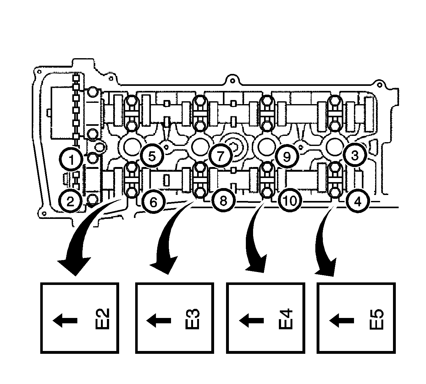
- Remove the exhaust camshaft using several steps, uniformly loosen and remove the 10 bearing cap bolts in the sequence shown in the illustration.
- Remove the 5 bearing caps.
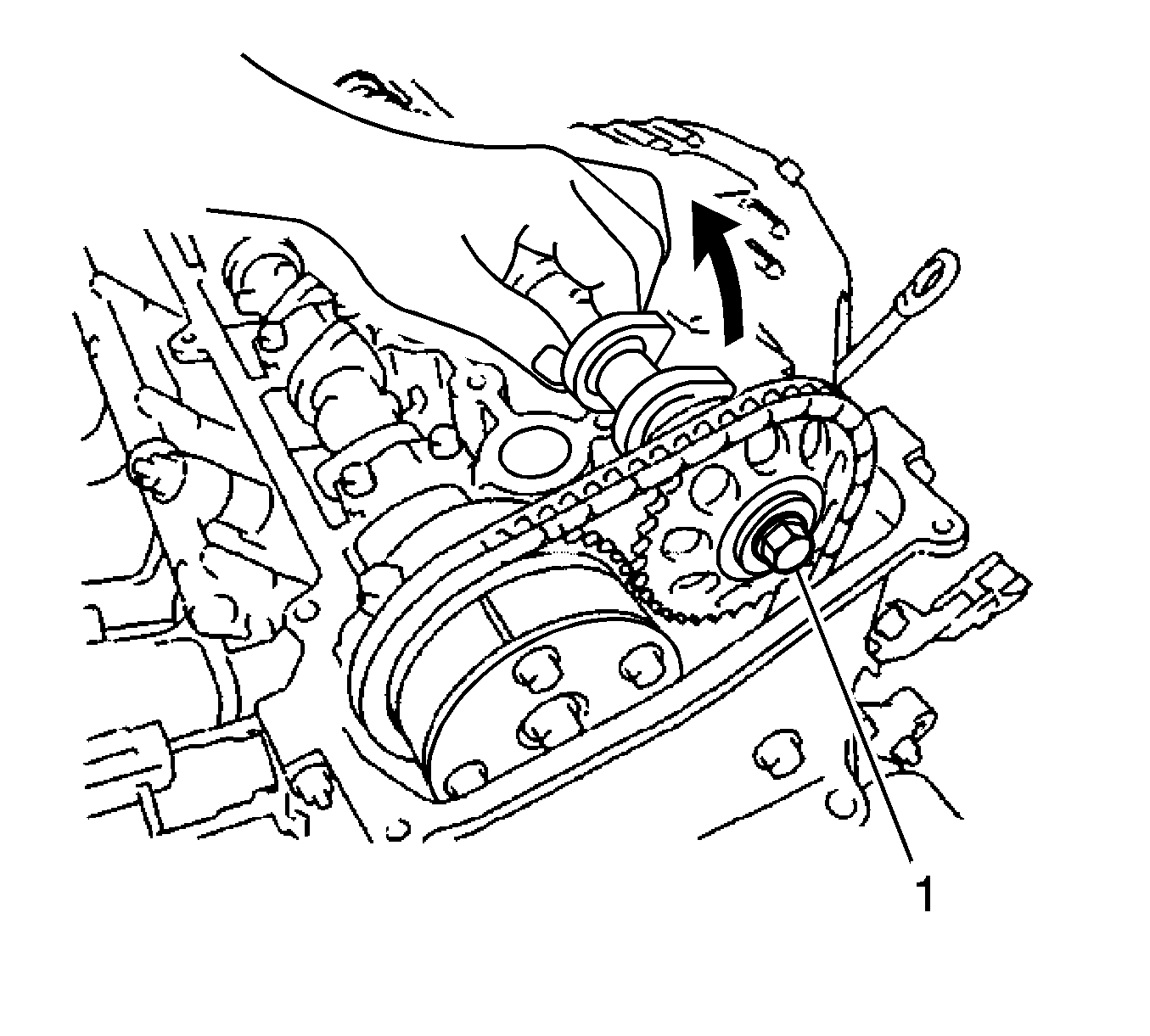
- While holding the exhaust camshaft by hand, remove the camshaft timing sprocket set bolt (1).
- Remove the camshaft timing sprocket from the No. 2 camshaft with the timing chain wrapped on the sprocket.
- Remove the camshaft timing sprocket from the timing chain.
Installation Procedure
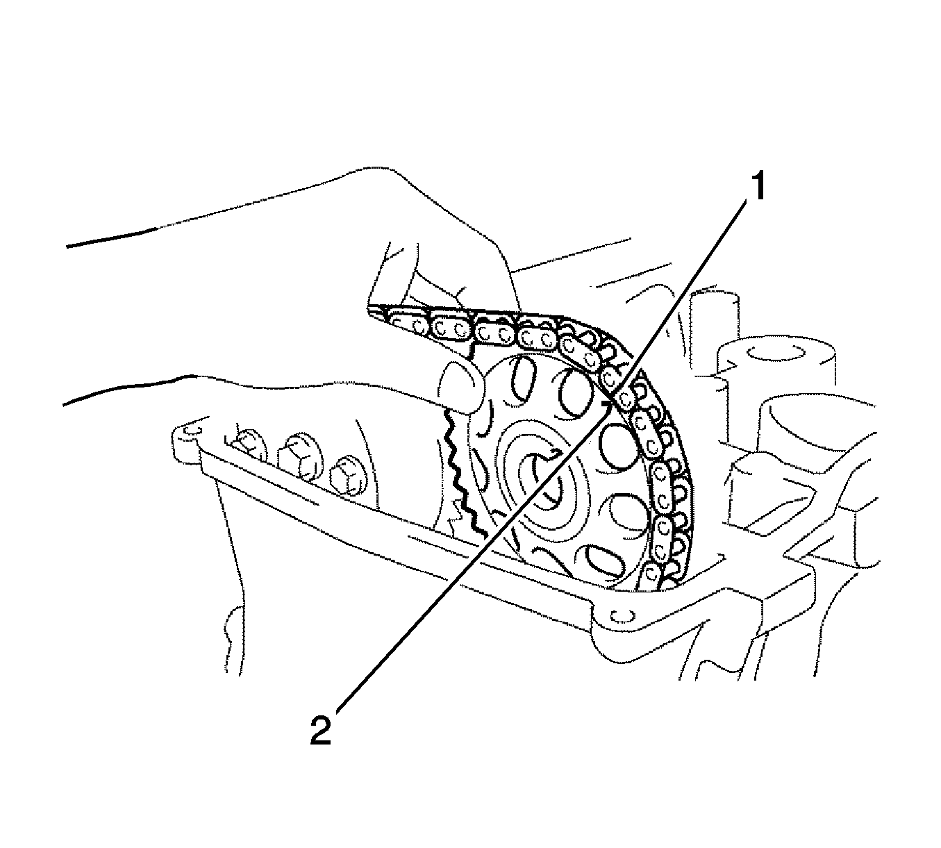
- Install the exhaust camshaft.
| 1.1. | Apply a light coat of engine oil to the journal portion of the exhaust camshaft. |
| 1.2. | Put the exhaust camshaft on the cylinder head with the paint mark (1) on the chain aligned with the timing mark (2) on the camshaft timing sprocket. |
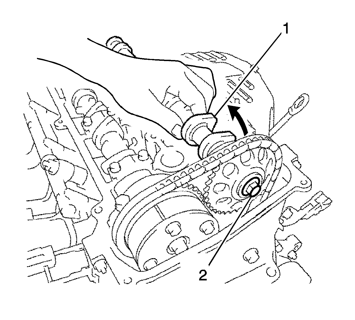
- While holding the exhaust camshaft by hand, temporarily tighten the camshaft timing sprocket set bolt (2).
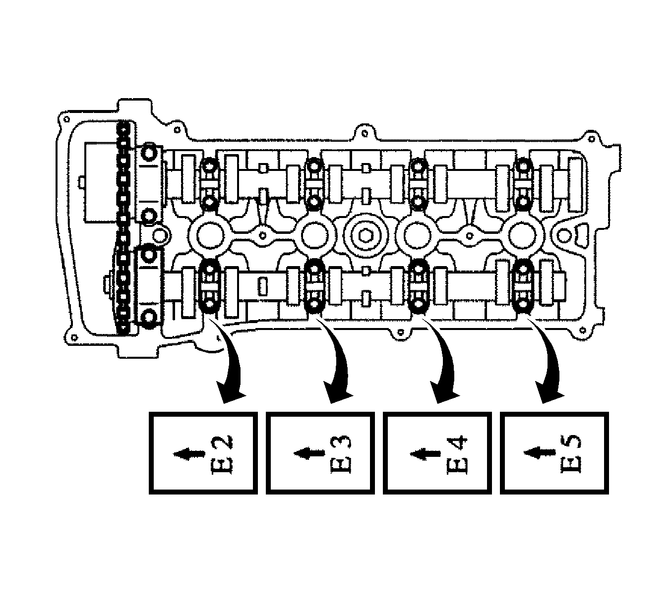
- Examine the front marks and numbers, and check that the order is as shown in the illustration. Then install the bearing caps onto the cylinder head.
- Apply a light coat of engine oil to the threads and under the heads of the bearing cap bolts.
Caution: Refer to Fastener Caution in the Preface section.
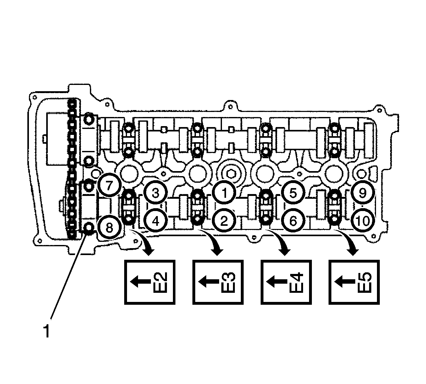
- Using several steps, uniformly install the 10 bearing cap bolts (1) in the sequence shown in the illustration and tighten.
| • | The thrust bearing bolts to
30 N·m (22 lb ft). |
| • | The remaining bearing bolts to
9.0 N·m (80 lb in). |
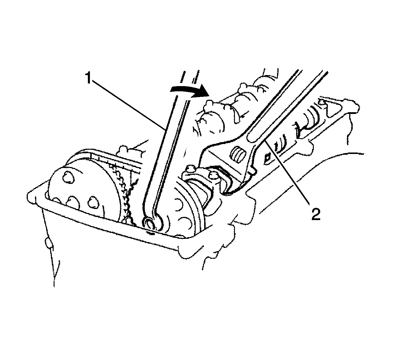
- While holding the camshaft with a wrench (2), install the camshaft timing sprocket set bolt and tighten to
54 N·m (40 lb ft).
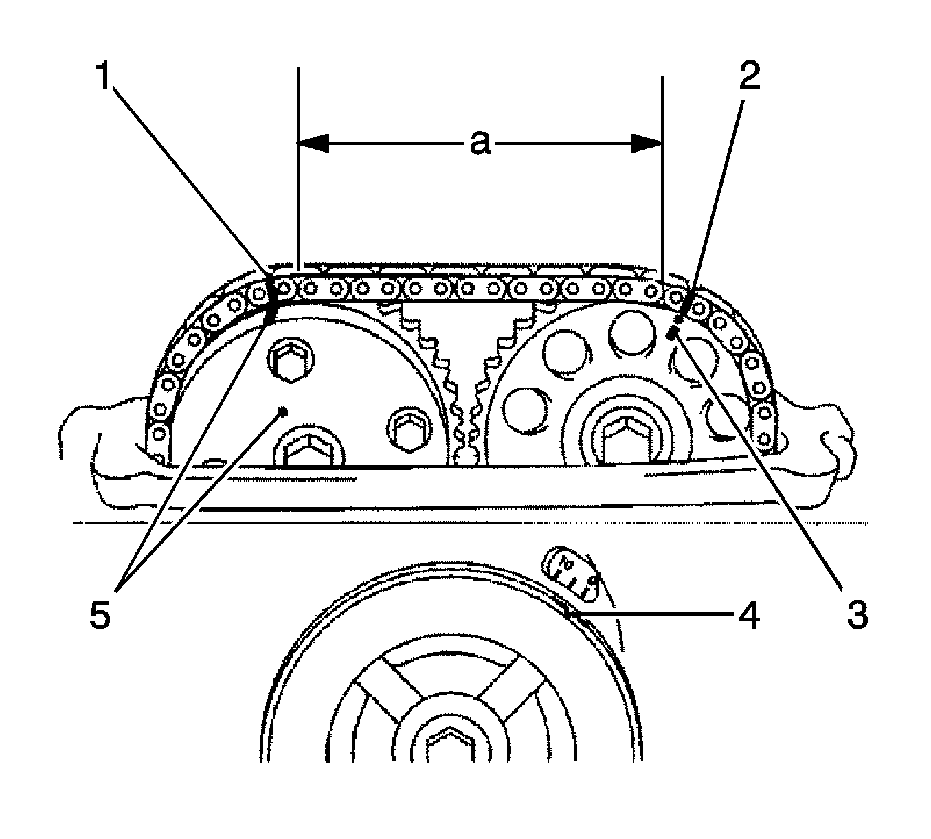
- Check that the paint marks (1, 2) on the chain are aligned with the timing marks (3, 5) on the camshaft timing gear and camshaft timing sprocket.
Also, check that the crankshaft pulley groove (4) is aligned with the timing mark 0 on the timing mark chain cover.
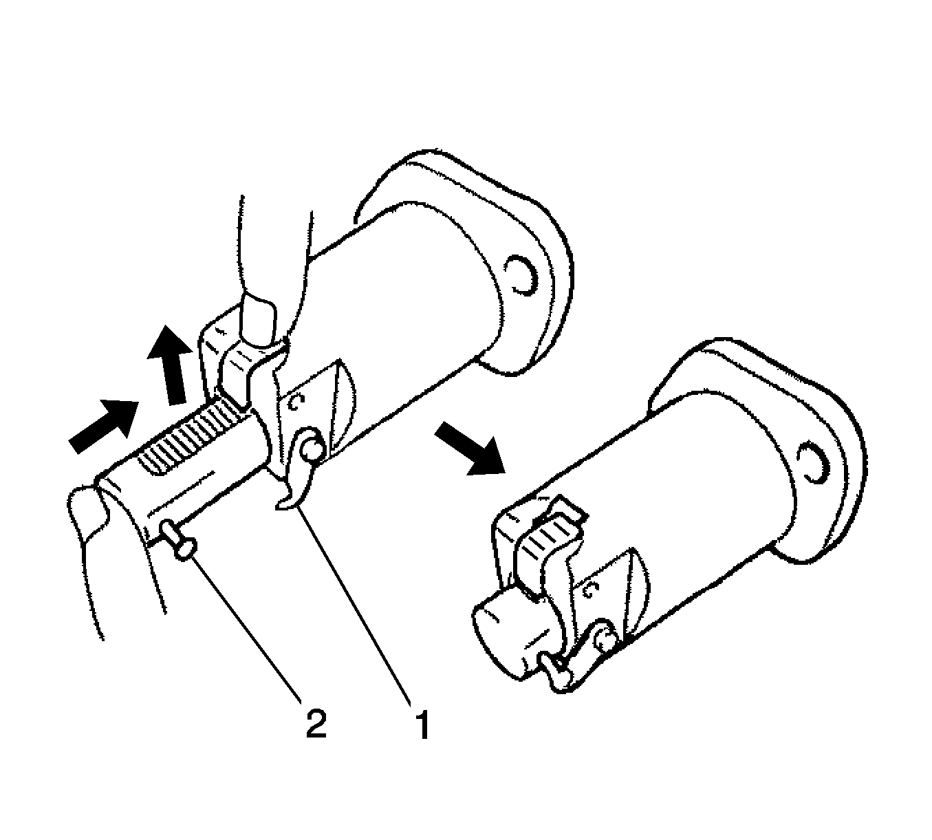
- Install the chain tensioner assembly. Release the ratchet pawl, then fully push in the plunger and hook the hook (1) to the pin (2) so that
the plunger is in the position shown in the illustration.
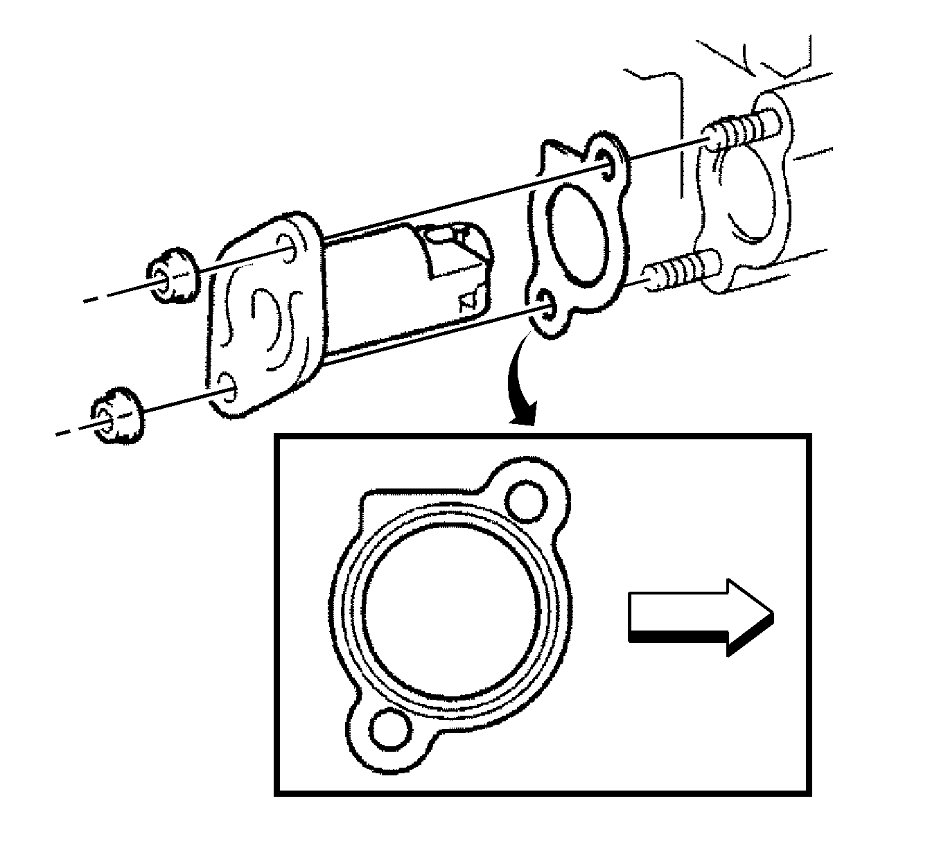
Note: When installing the chain tensioner, set the hook again if the hook releases the plunger.
- Install a new gasket and the chain tensioner with the 2 nuts and tighten to
9.0 N·m (80 lb in).
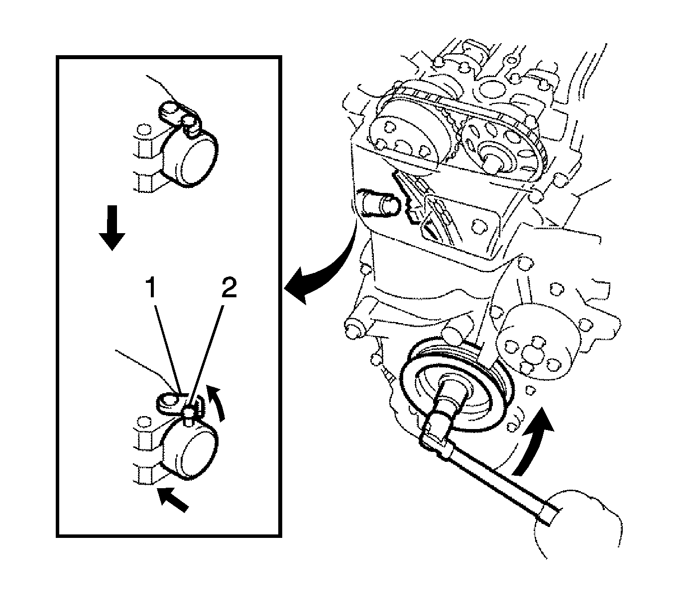
- Turn the crankshaft counterclockwise, then disconnect the plunger knock pin (2) from the hook (1).
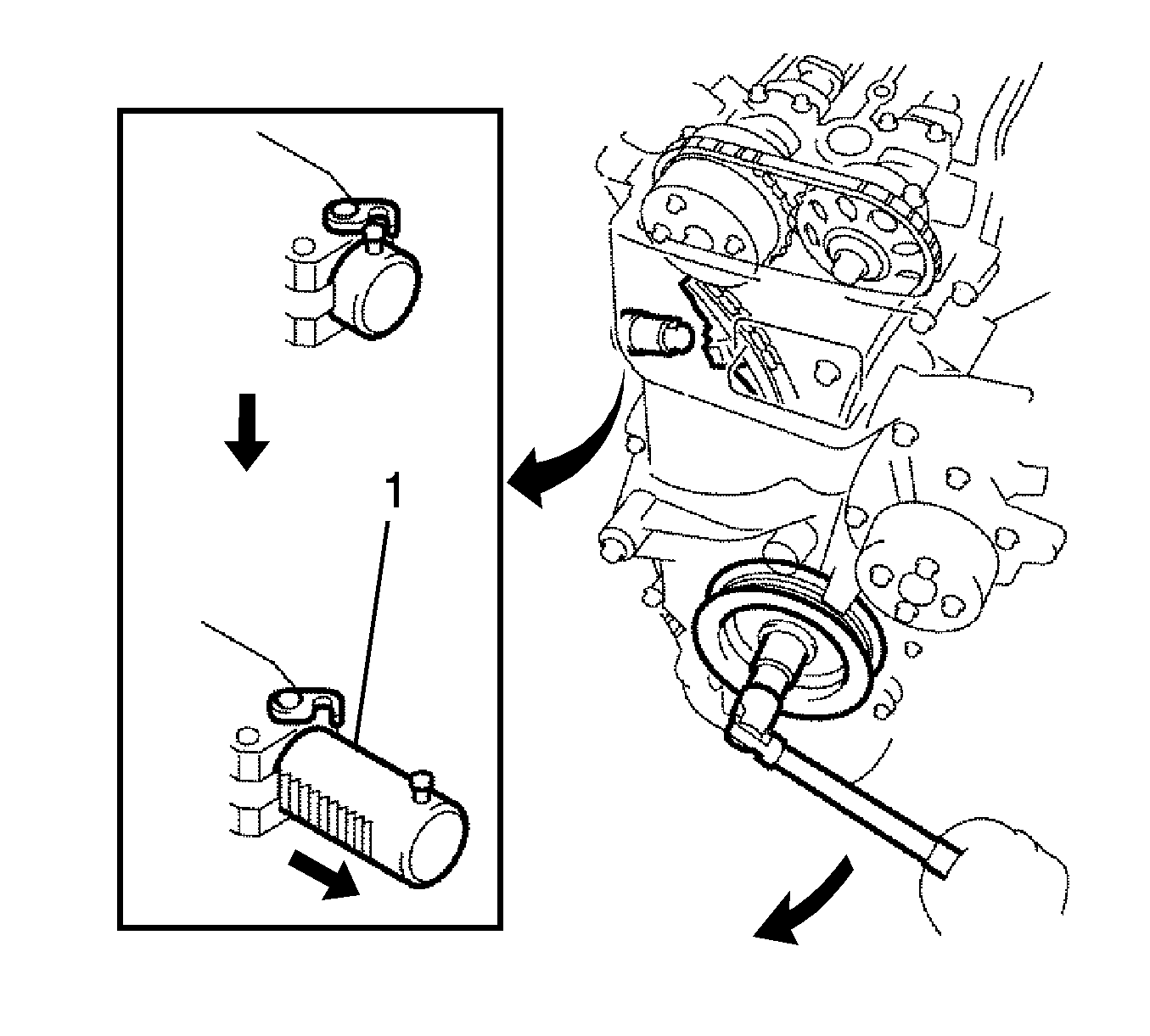
- Turn the crankshaft clockwise, then check that the plunger (1) is extended.
- Set No. 1 cylinder to TDC/compression.
- Check the valve clearance. Refer to
Valve Clearance Adjustment.
- Remove any old packing material from the contact surface.
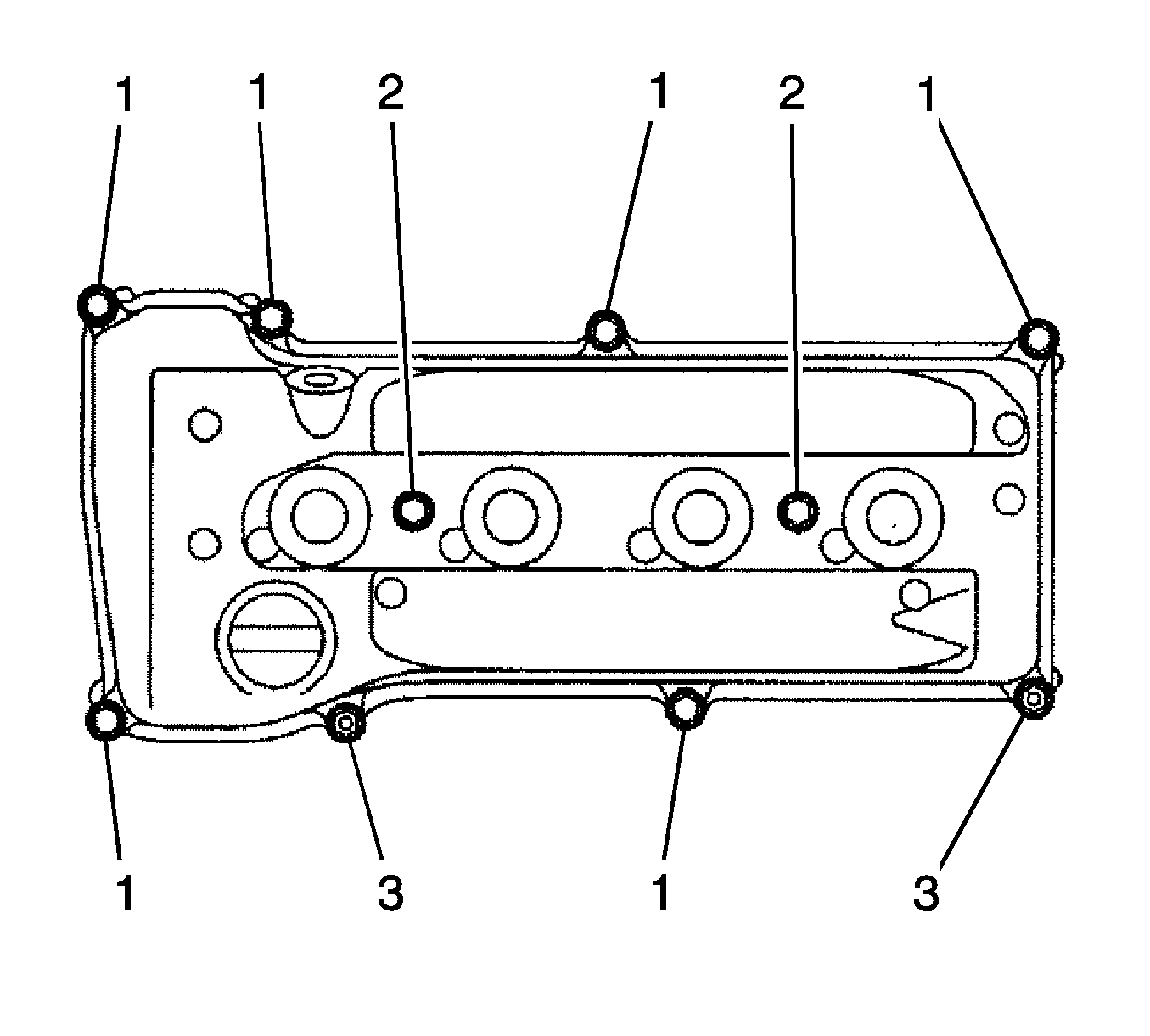
- Install the cylinder head cover gasket and subassembly with the 8 bolts (1, 2) and 2 nuts (3) and tighten.
| • | Bolts 1 to
11 N·m (8 lb ft) |
| • | Bolts 2 to
14 N·m (10 lb ft) |
| • | Nuts to
11 N·m (8 lb ft) |

- Install the 2 engine wire harness brackets with the 2 bolts (1, 2) and tighten to
8.4 N·m (74 lb in).

- Connect the 2 ventilation hoses (1, 2) to the cylinder head cover.
- Install the spark plug. Refer to
Spark Plug Replacement.
- Install the ignition coil assembly. Refer to
Ignition Coil Replacement.
- Inspect for oil leak.
- Inspect the ignition timing.
- Install the engine cover sub-assembly. Refer to
Engine Cover Replacement.
- Install the engine under right cover.


