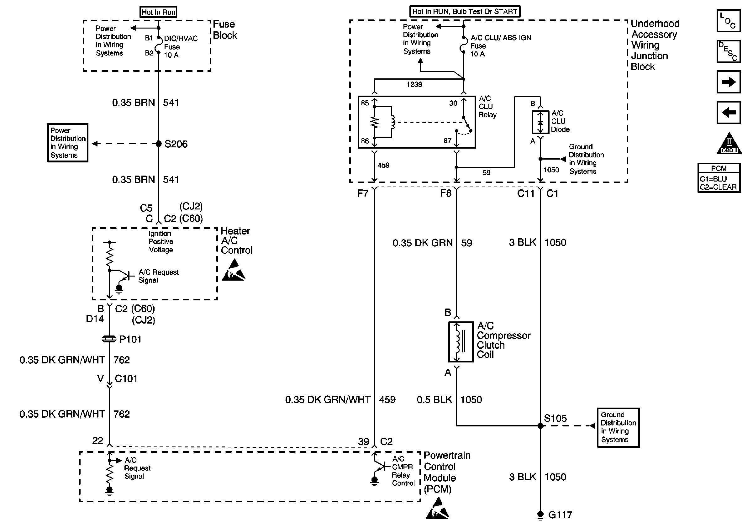
Refer to Engine Controls Schematics
Heater A/C Control and A/C Compressor Clutch Coil

for a wiring diagram.
Circuit Description
When you select an A/C mode, the A/C control head or the A/C programmer
supplies a 12-volt signal to the powertrain control module (PCM) A/C request
input. The PCM controls the A/C compressor clutch relay The PCM
provides a ground path for the A/C relay coil. When the A/C relay
is engaged, battery voltage is supplied to the compressor clutch
coil. The PCM will enable the A/C compressor clutch whenever
the engine is running and the A/C has been requested, unless
one or more of the following conditions are present:
| • | The throttle angle is more than 96 percent. |
| • | The A/C head pressure is more than 440 psi (4.6 volts)
or less than 32 psi (0.3 volt), as determined by the A/C refrigerant
pressure sensor. |
| • | The Ignition 1 voltage is less than 10 volts. |
| • | The engine speed is more than 4392 RPM for less than 1 second. |
| • | The engine speed is more than 4400 RPM for any amount of
time. |
| • | The engine coolant temperature (ECT) is more than 124°C (255°F). |
| • | The intake air temperature (IAT) is less than 5°C (41°F). |
Any of the above conditions will inhibit A/C compressor relay operation.
Diagnostic Aids
Inspect for the following conditions:
| • | A poor connection at the PCM--Inspect harness connectors
for the following conditions: |
| - | Improperly-formed or damaged terminals |
| - | Poor terminal-to-wire connections |
| • | A damaged harness--Inspect the wiring harness for damage.
If the harness appears OK, disconnect the PCM, turn ON the ignition, and observe
a Digital Multimeter (DMM) connected to the A/C relay control circuit
at the PCM harness connector while moving connectors and wiring
harnesses related to the A/C relay. A change in voltage will
indicate the location of the malfunction. |
Inspect for conditions that will disable A/C operation:
| • | The throttle angle is more than 96 percent. |
| • | The A/C head pressure is more than 440 psi (4.6 volts),
or less than 32 psi (0.3 volt), as determined by the A/C refrigerant
pressure sensor. |
| • | The Ignition 1 voltage is less than 10 volts. |
| • | The engine speed is more than 4392 RPM for less than 1 second. |
| • | The engine speed is more than 4400 RPM for any amount of
time. |
| • | The ECT is more than 124°C (255°F). |
| • | The IAT is less than 5°C (41°F). |

