- Disconnect the battery ground cable. Refer to Battery Negative Cable Disconnection and Connection.
- Remove the engine covers. Refer to Engine Cover Replacement.
- Remove the air intake duct. Refer to Air Cleaner Inlet Duct Replacement.
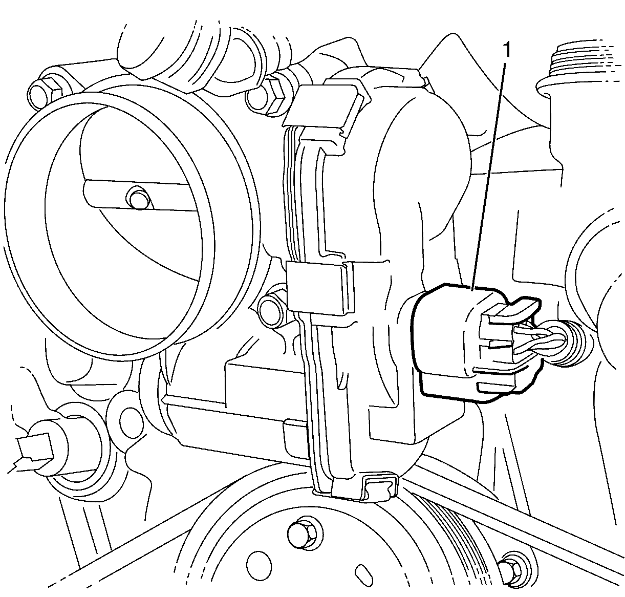
- Disconnect the throttle body electrical connector (1).
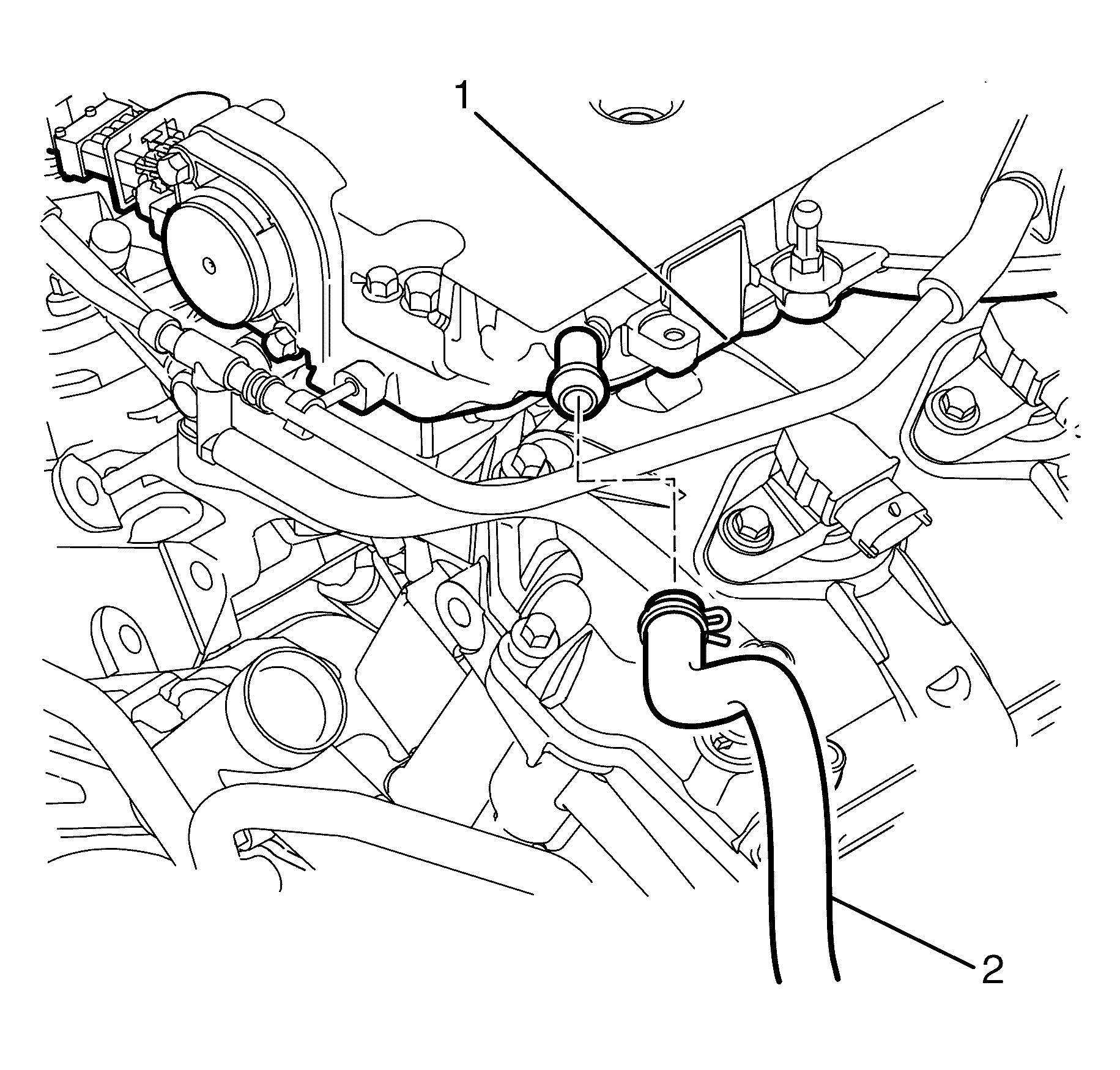
- Disconnect the brake booster vacuum hose (2) from the intake manifold (1).
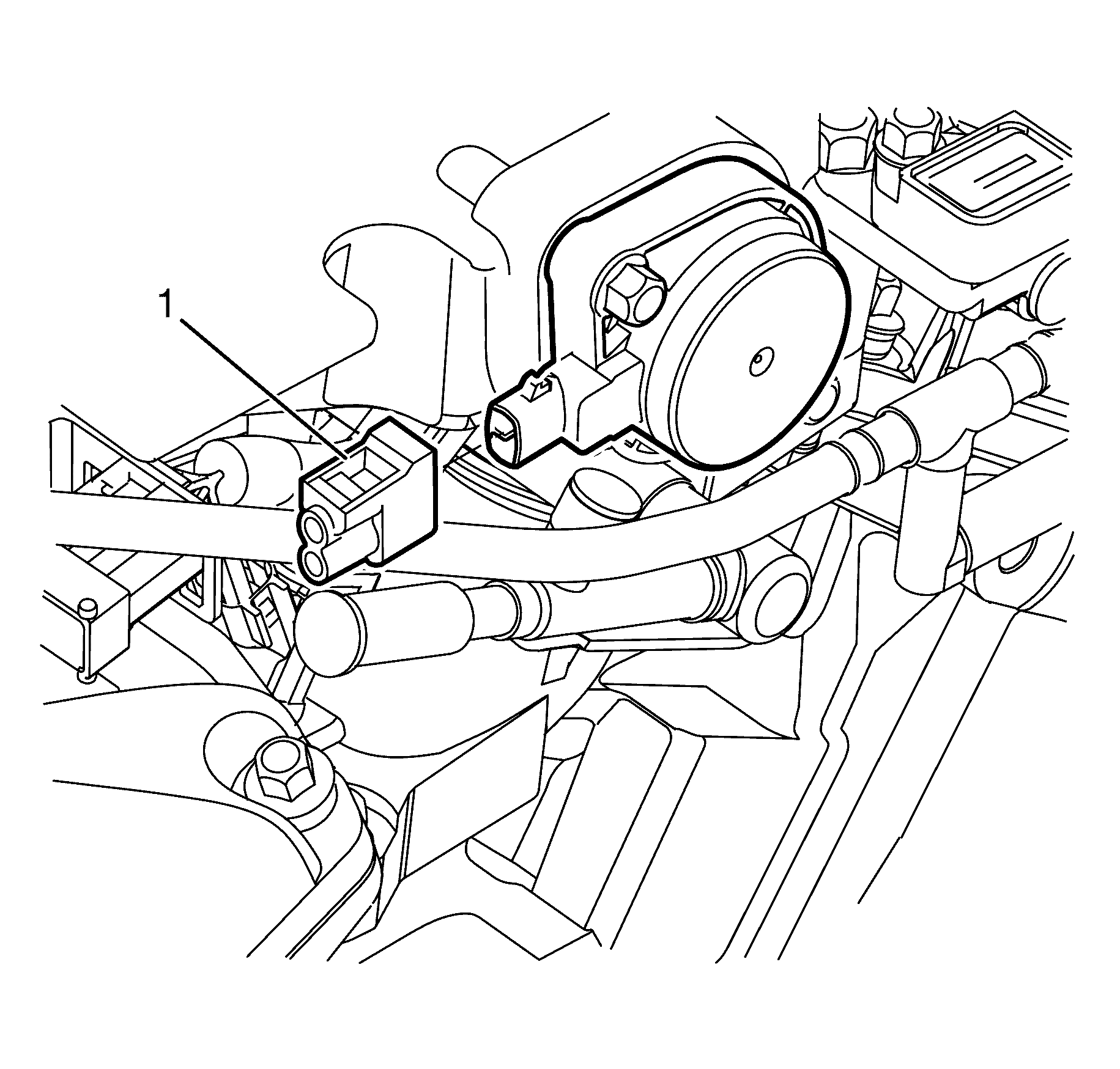
- Disconnect the Inlet Manifold Runner Control (IMRC) solenoid connector (1).
- Disconnect the evaporative emission (EVAP) purge line (1) from the purge solenoid (2). Refer to Metal Collar Quick Connect Fitting Service or Plastic Collar Quick Connect Fitting Service.
- Plug or cap the (EVAP) purge line (1) and the purge solenoid (2) ends.
- Remove the PCV tube and PCV fresh air tubes. Refer to Positive Crankcase Ventilation Hose/Pipe/Tube Replacement.
- Disconnect the EVAP valve electrical connector (4)
- Disconnect the fuel injector harness electrical connector (3)
- Remove the fuel injector harness electrical connector/EVAP valve mounting bracket to intake manifold retaining bolt (2).
- Reposition the fuel injector harness electrical connector/EVAP valve mounting bracket (5) away from the intake manifold (1).
- Disconnect the fuel feed pipe (2) from the fuel rail (1). Refer to Metal Collar Quick Connect Fitting Service or Plastic Collar Quick Connect Fitting Service.
- Plug or cap the fuel feed pipe (2) and fuel rail (1) ends.
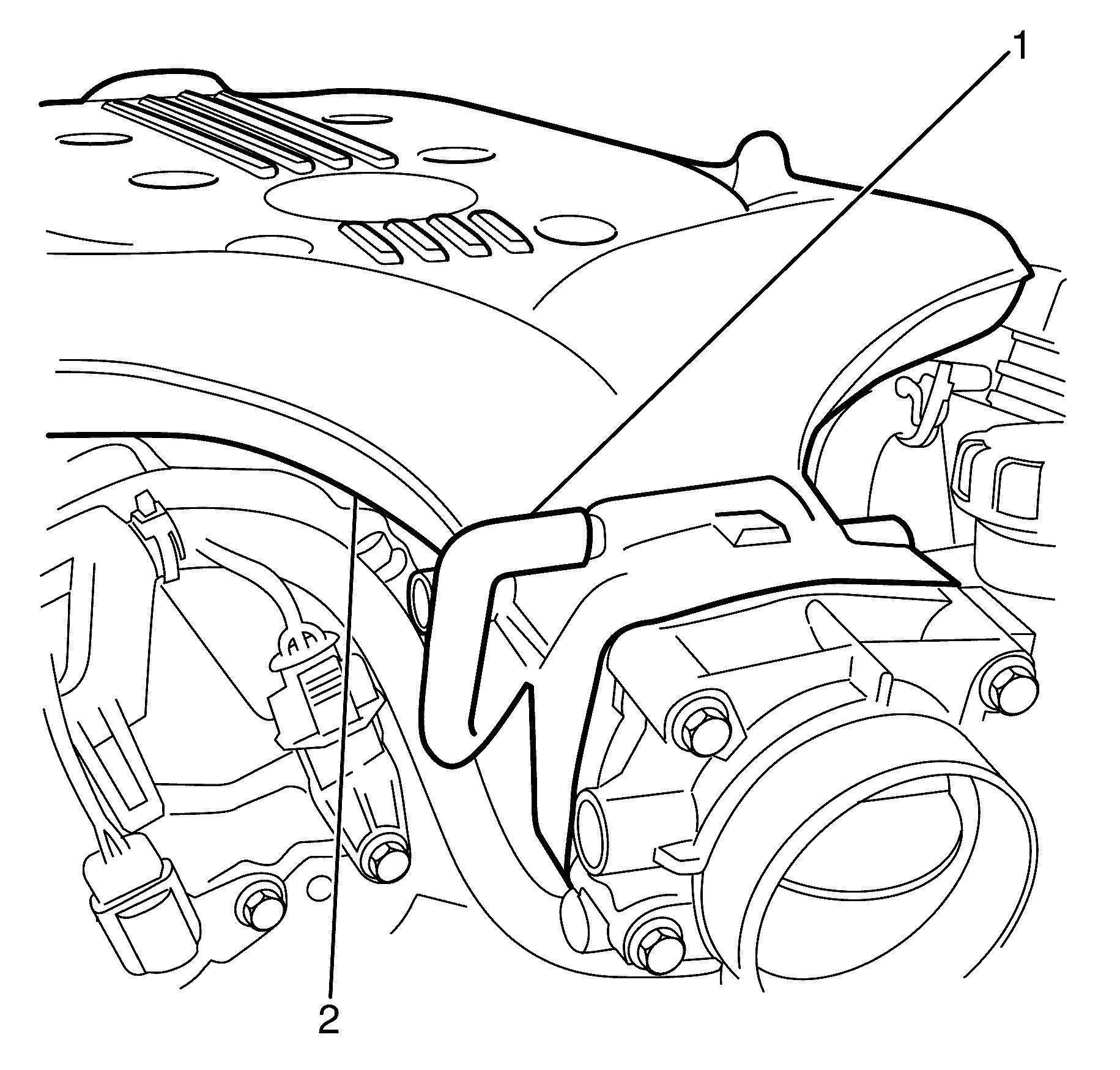
- Disconnect the EVAP line (1) from the intake manifold (2).
- Remove the intake manifold to cylinder head retaining bolts (1).
- Remove the intake manifold assembly (2).
- Plug the cylinder heads and engine valley with a clean lint free cloth.
- Disassemble the intake manifold as to replace the lower intake manifold. Refer to Intake Manifold Disassemble.
- Clean and inspect the intake manifold and the sealing surfaces. Refer to Intake Manifold Cleaning and Inspection.
Warning: Refer to Battery Disconnect Warning in the Preface section.


Note: Plug or cap the fuel feed pipe (2) and fuel rail (1) ends to prevent fuel leaks and/or contamination.


Note:
• DO NOT remove the upper intake manifold to lower intake manifold retaining bolts (3). • DO NOT kink or damage the fuel pipe.
Note: The cylinder heads and engine valley must be plugged with a clean lint free cloth to prevent foreign matter entry into the engine.
Installation Procedure
- Assemble the intake manifold as necessary. Refer to Intake Manifold Assemble.
- Remove the clean lint free cloth from the cylinder heads and engine valley.
- Install the lower intake manifold gasket.
- Install the intake manifold assembly (2).
- Install the intake manifold using the cylinder head retaining bolts (1) and tighten to 23 N·m (17 lb ft).
- Connect the EVAP line (1) to the intake manifold (2).
- Remove the plug or cap at the fuel feed pipe (1) and fuel rail (2) ends
- Connect the fuel feed pipe (1) to the fuel rail (2). Refer to Metal Collar Quick Connect Fitting Service or Plastic Collar Quick Connect Fitting Service.
- Install the fuel injector harness electrical connector/EVAP valve mounting bracket (5) to the intake manifold (1).
- Install the fuel injector harness electrical connector/EVAP valve mounting bracket to intake manifold retaining bolt (2).
- Connect the fuel injector harness electrical connector (3)
- Connect the EVAP valve electrical connector (4)
- Install the PCV tube and PCV fresh air tubes. Refer to Positive Crankcase Ventilation Hose/Pipe/Tube Replacement.
- Remove the plug or cap from the (EVAP) purge line (2) and the purge solenoid (1) ends.
- Connect the evaporative emission (EVAP) purge line (2) from the purge solenoid (1). Refer to Metal Collar Quick Connect Fitting Service or Plastic Collar Quick Connect Fitting Service.
- Connect the Inlet Manifold Runner Control (IMRC) electrical connector (1).
- Connect the brake booster vacuum hose (2) to the intake manifold (1).
- Connect the throttle body electrical connector (1).
- Install the air intake duct. Refer to Air Cleaner Inlet Duct Replacement.
- Install the engine covers. Refer to Engine Cover Replacement.
- Connect the battery ground cable. Refer to Battery Negative Cable Disconnection and Connection.

Note: Inspect and replace the lower intake manifold gasket only if the gasket is worn or damaged.

Caution: Refer to Fastener Caution in the Preface section.
Note: Tighten the intake manifold to cylinder head retaining bolts (1) in a circular pattern starting at the center (long bolts) and moving outward.


