Removal Procedure
- Remove the wheel hub and knuckle assembly. Refer to Knuckle Replacement.
- Secure the wheel hub and knuckle assembly using a suitable vice.
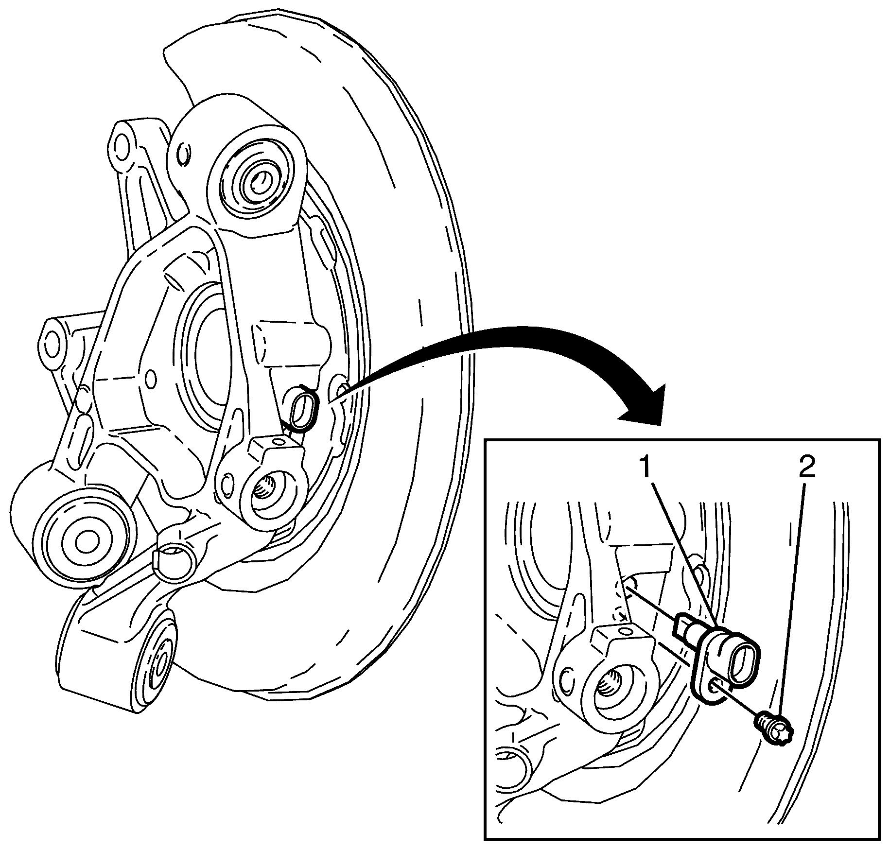
- Remove the wheel speed sensor to knuckle retaining bolt (2).
- Remove the wheel speed sensor (1).
- Remove the wheel hub flange using a suitable workshop press.
- Remove the park brake shoes. Refer to Parking Brake Shoe Replacement.
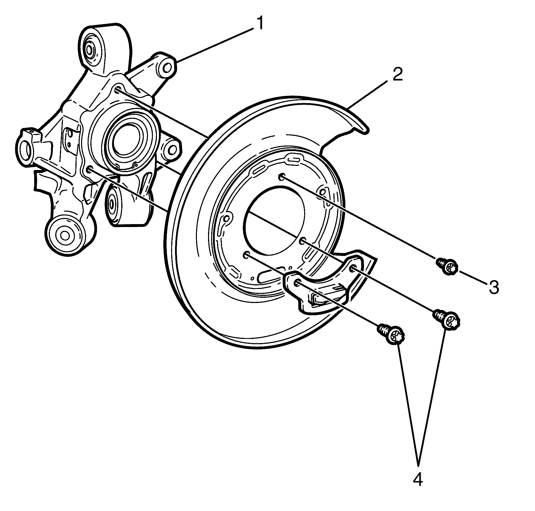
- Remove the disc brake backing plate to knuckle retaining bolts (3 and 4).
- Remove the disc brake backing plate (2) from the knuckle (1).
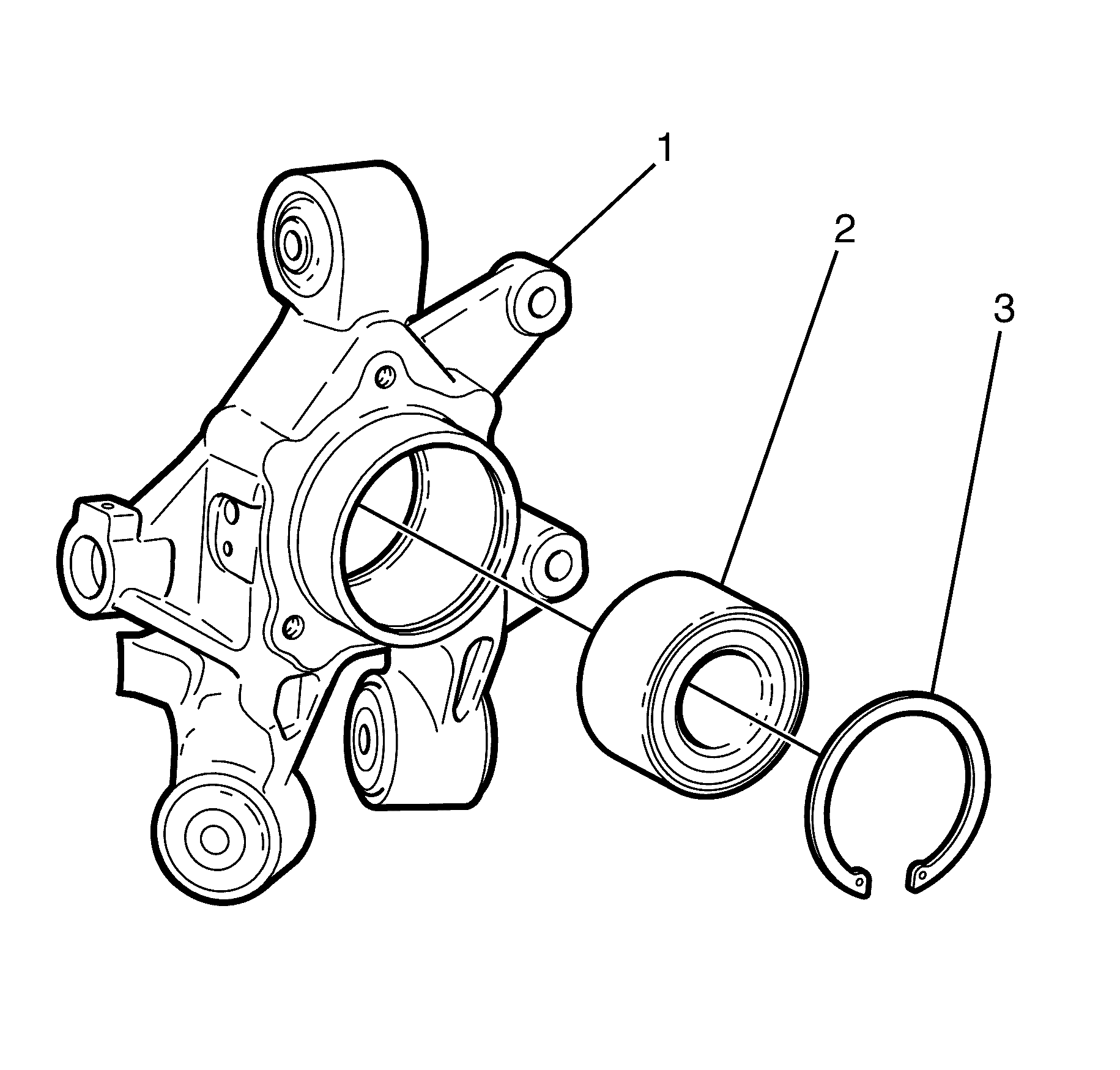
- Remove the wheel bearing retaining circlip (3) using suitable circlip pliers.
- Press the wheel bearing (2) from the knuckle (1) using a suitable workshop press.
Warning: Refer to Safety Glasses Warning in the Preface section.

Note: The wheel bearing will be damaged when pressing out the wheel hub flange. The wheel bearing must be replaced every time the wheel hub is removed.


Note: The wheel bearing will be damaged when pressing out the wheel hub flange. The wheel bearing must be replaced every time the wheel hub is removed.
Discard the wheel bearing.
Installation Procedure
- Install the NEW wheel bearing (2) to the knuckle (1) using a workshop press.
- Install the wheel bearing retaining circlip (3) using suitable circlip pliers.
- Install the disc brake backing plate (2) to the knuckle (1).
- Install the upper disc brake backing plate using the knuckle retaining bolt (3) and tighten to 60 N·m (44 lb ft).
- Install the lower disc brake backing plate using the knuckle retaining bolts (4) and tighten to 130 N·m (96 lb ft).
- Install the park brake shoes. Refer to Parking Brake Shoe Replacement.
- Install the wheel hub flange (1) using a suitable press.
- Install the wheel speed sensor (1).
- Install the wheel speed sensor using the knuckle retaining bolt (2) and tighten to 7 N·m (62 lb in).
- Remove the hub and knuckle assembly from the vice.
- Install the wheel hub and knuckle assembly. Refer to Knuckle Replacement.
Warning: Refer to Safety Glasses Warning in the Preface section.

Note: Prior to installing the NEW wheel bearing it is essential that the correct orientation is attained, the wheel speed sensor decoder ring MUST face inboard, towards the wheel speed sensor. Failure to install in the correct orientation will result in ABS/ESP faults.

Caution: Refer to Fastener Caution in the Preface section.
Note: The wheel hub flange (1) must be fully seated against the wheel bearing.

Caution: Refer to Fastener Caution in the Preface section.
