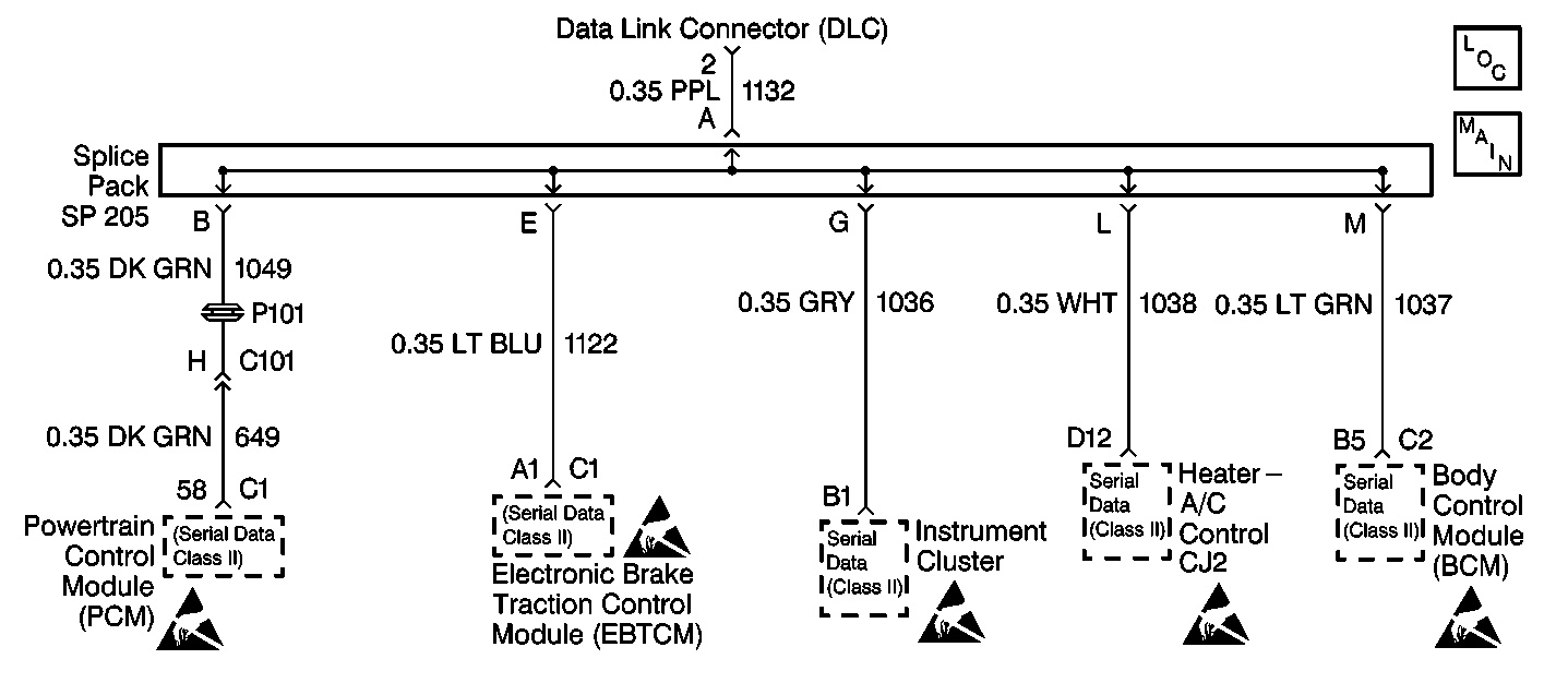
Circuit Description
The oscillator is a device used in the instrument cluster to send and interpret data between the other vehicle systems along the Class II serial data link. Its major function is to send or receive the different binary (bytes) information between the instrument cluster and the other vehicle systems. The oscillator will transmit binary information to other components and then expect to receive a binary message stating the information was received. After three attempts by the instrument cluster to transmit information and receive a confirmation have failed, this DTC will be set.
Conditions for Setting the DTC
- The oscillator is being disrupted by outside Radio Frequency (RF) interference.
- Condition can occur any time.
Action Taken When the DTC Sets
| • | The instrument cluster stores DTC B1096 in memory. |
| • | The SERVICE VEHICLE SOON indicator turns on. |
Conditions for Clearing the DTC
| • | Under all fault conditions the ignition switch must be cycled from on to off, back to on before this DTC can change from current to history. |
| • | A history DTC will clear after 100 drive cycles if the condition for this DTC is no longer present. |
| • | Use a scan tool. |
Diagnostic Aids
The following conditions may cause an intermittent malfunction to occur:
| • | Radio Frequency (RF) interference induced into the Class II serial data link. |
| • | Improperly installed aftermarket equipment. |
| • | Illegal tampering with the instrument cluster. |
Test Description
The number below refers to the step number on the diagnostic table.
Step | Action | Value(s) | Yes | No |
|---|---|---|---|---|
1 | Was the instrument cluster diagnostic system check performed? | -- | ||
Does DTC U1096 reset as a current DTC in the instrument cluster? | -- | |||
3 | Replace the instrument cluster. Refer to Instrument Cluster Replacement for service procedures. Is the repair complete? | -- | -- | |
4 | The malfunction is not present at this time. Refer to Diagnostic Aids for additional information regarding this DTC. | -- | -- | -- |
5 |
Are there any DTCs stored in the instrument cluster? | -- | System OK |
