Brake Pads Replacement Front Wheel
Removal Procedure
Use original equipment brake lining material for this vehicle. Original equipment brake parts provide the proper brake balance for stopping distance and for braking control. The intended brake balance for this vehicle can change if original equipment brake lining materials are not used.
- Remove the caliper. Refer to Brake Caliper Replacement .
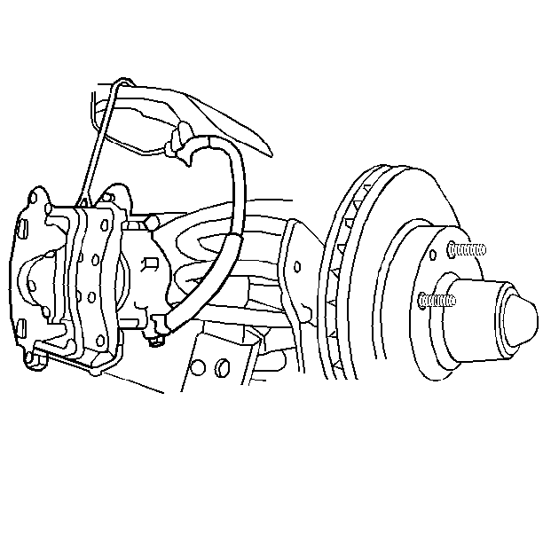
- Suspend the caliper.
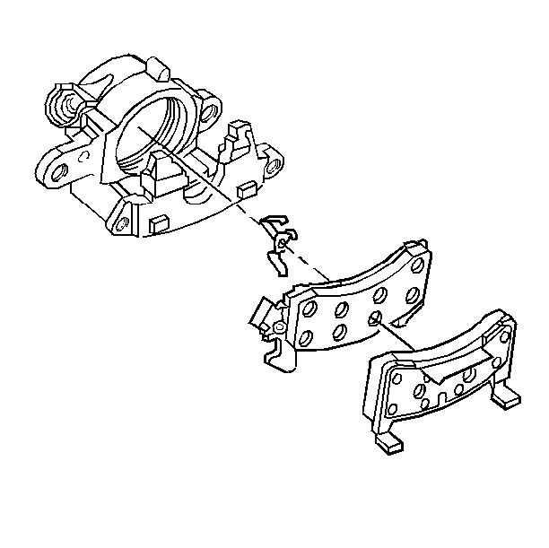
- Remove the brake shoe and lining assemblies from the caliper.
- Remove the retainer spring from the inboard brake shoe.
Important: Do not disconnect the brake hose from the caliper.
Notice: Do not allow the brake components to hang from the flexible brake hoses. Damage to the brake hoses could result.
Installation Procedure
- Install the retainer spring on the inboard brake shoe.
- Install the brake shoe and lining assemblies in the caliper.
- Install the caliper. Refer to Brake Caliper Replacement .
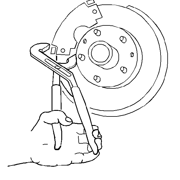
- Compress the brake shoe ears against the caliper.

Notice: Make sure the brake hose is not twisted or kinked after installation. Damage to the hose could result.
Important: Before moving the vehicle, pump the brake pedal several times in order to make sure the pedal is firm. Do not move the vehicle until you get a firm brake pedal. Check the brake fluid level in the master cylinder reservoir after pumping the brake pedal.
Brake Pads Replacement Rear Wheel
Removal Procedure
Caution: Do not move the vehicle until a firm brake pedal is obtained. Failure to obtain a firm pedal before moving vehicle may result in personal injury.
- Remove two-thirds of the brake fluid from the master cylinder reservoir.
- Raise and suitably support the vehicle. Refer to Lifting and Jacking the Vehicle in General Information.
- Mark the relationship of the wheel to the axle flange.
- Remove the tire and the wheel. Refer to Wheel Removal in Tires and Wheels. Install two wheel nuts to retain the rotor.
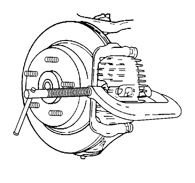
- Compress the caliper piston enough for clearance. Use a C-clamp.
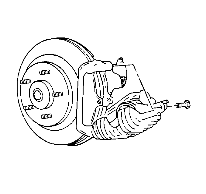
- Remove the upper caliper bolt .
- Pivot the caliper body down in order to access the pads. Do not remove the caliper body.
- Remove the brake pads from the caliper bracket.
- Remove the rear brake pad spring shim.
- Inspect the caliper bracket boots for the following conditions:
- Inspect the piston boot for the following conditions:
- Inspect the caliper bolts for corrosion or damage. If corrosion exists, use new components (including bushings) when installing the caliper. Do not attempt to polish away the corrosion.
| • | Cuts |
| • | Tears |
| • | Deterioration |
| • | Replace the bracket boots if damage exists. Refer to Brake Caliper Bracket Replacement . |
| • | Cuts |
| • | Tears |
| • | Deterioration |
| • | Replace the piston boot if damage exists. Refer to Brake Caliper Overhaul - Rear . |
Installation Procedure
Important: Before installing new brake pads, wipe the outside surface of the caliper boot clean. Use denatured alcohol.
- Bottom the piston into the caliper bore.
- Install the rear brake pad spring shim.
- Install the pads to the caliper bracket.
- Swing the caliper upward in position around the pads.
- Lubricate the bolt and the bolt boot. Use silicone grease.
- Install the upper caliper bolt.
- Remove the wheel nuts securing the rotor to the hub and bearing.
- Install the tires and the wheels. Refer to Wheel Installation in Tires and Wheels. Align the previous marks on the wheel, hub and bearing.
- Lower the vehicle.
- Fill the master cylinder to the proper level with clean brake fluid. Refer to Master Cylinder Reservoir Filling .
- Apply approximately 778 N (175 lb) of force three times to the brake pedal in order to seat the pads against the rotor.
- Burnish the pads and the rotors. Refer to Brake Pad and Rotor Burnishing .
Use a C-clamp when installing new brake pads in order to clamp the piston at the same time. Use a metal plate or wooden block across the face of the piston. Do not damage the piston or the caliper boot.
Important: Lift the inner edge caliper boot next to the piston. Press out any trapped air. The boot must lay flat below the level of the piston face.
Important: The wear sensor is on the outside shoe. The sensor is positioned at the trailing edge (downward) of the pad during forward wheel rotation.

Notice: Use care to avoid damaging pin boot when rotating caliper.
Notice: Use the correct fastener in the correct location. Replacement fasteners must be the correct part number for that application. Fasteners requiring replacement or fasteners requiring the use of thread locking compound or sealant are identified in the service procedure. Do not use paints, lubricants, or corrosion inhibitors on fasteners or fastener joint surfaces unless specified. These coatings affect fastener torque and joint clamping force and may damage the fastener. Use the correct tightening sequence and specifications when installing fasteners in order to avoid damage to parts and systems.
Tighten
Tighten the caliper bolt to 43 N·m (32 lb ft).
