Removal Procedure
- Depressurize the air suspension system, if equipped. Refer to Air Suspension Depressurization.
- Disable the park brake cable automatic adjuster. Refer to Parking Brake Cable Adjuster Disabling.
- Raise the vehicle. Refer to Lifting and Jacking the Vehicle.
- Place jack stands at the front of the vehicle.
- Support the rear axle with jack stands.
- Remove the rear tire and wheel assemblies. Refer to Tire and Wheel Removal and Installation.
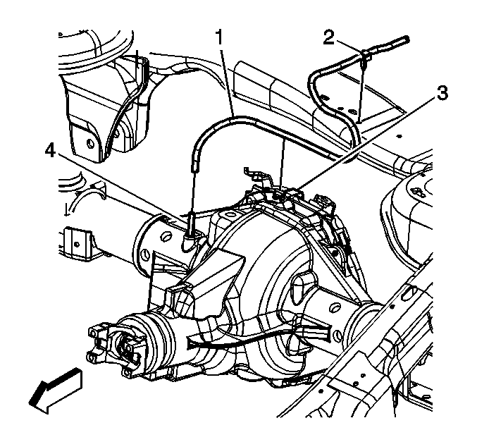
- Disconnect the rear axle vent tube (1).
- Remove the rear propeller shaft. Refer to Rear Propeller Shaft Replacement.
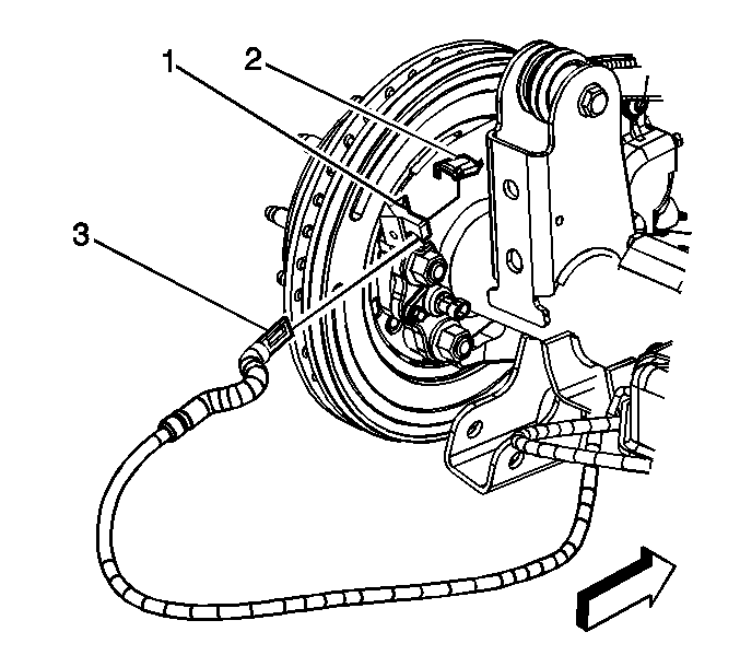
- Disconnect the left-rear park brake cable (3) from the backing plate (1), the park brake actuator (2), and the cable guide at the rear axle.
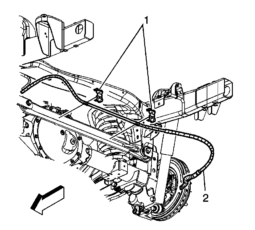
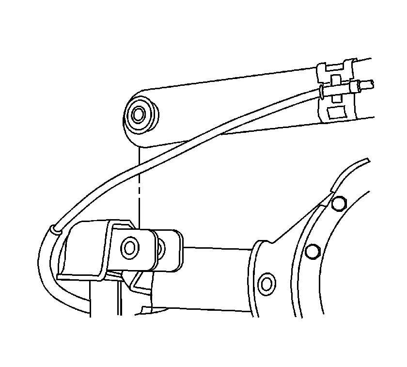
- Remove the park brake cable clips (1) from the track bar.
- Disconnect the right-rear park brake cable (2) from the backing plate, the park brake actuator, and from the cable guide at the rear axle.
- Remove the brake crossover pipe bracket bolt.
- Remove the brake crossover pipe, wheel speed sensor harness, and electronic locker harness from the rear axle and secure them to the body or frame.
- Remove the brake caliper and bracket assemblies from the rear axle and support them with heavy mechanics wire or equivalent. DO NOT disconnect the hydraulic brake flexible hose from the caliper.
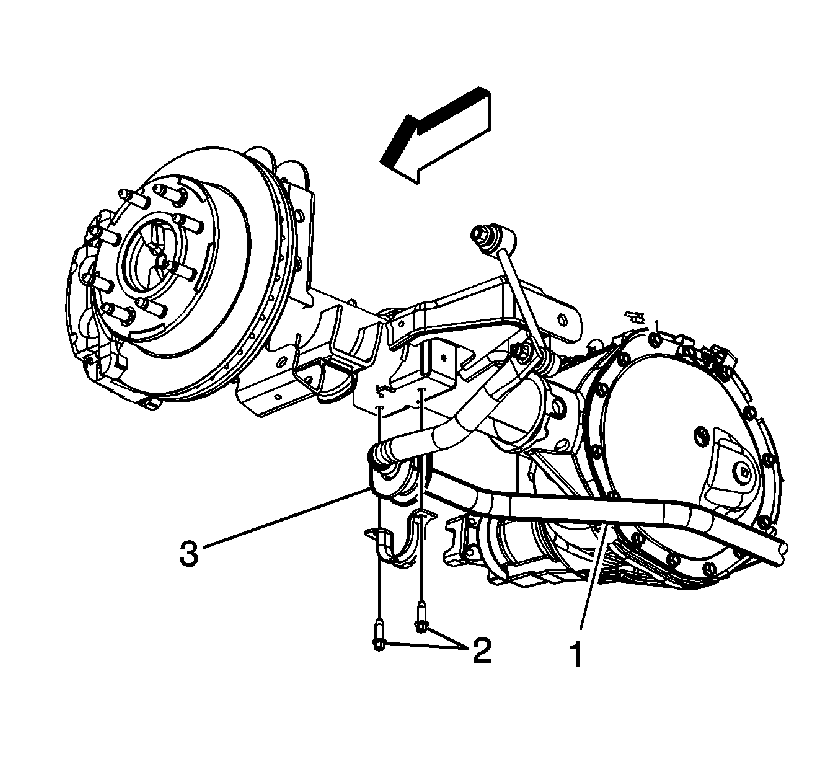
- Remove the rear stabilizer shaft insulator bracket bolts (2) from the rear axle.
- Pivot the stabilizer shaft (1) to the rear and secure it out of the way.
- Disconnect the track bar from the rear axle and suspend it out of the way.
- Disconnect the lower control arms from the rear axle. Refer to Rear Axle Lower Control Arm Replacement.
- Disconnect the upper control arms from the rear axle. Refer to Rear Axle Upper Control Arm Replacement.
- Remove the lower shock nuts and bolts from the rear axle shock bracket.
- Remove the coil springs, if equipped. Refer to Coil Spring Replacement.
- Remove the rear axle assembly from the vehicle.
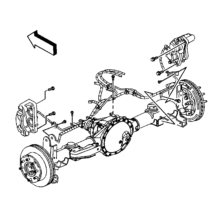
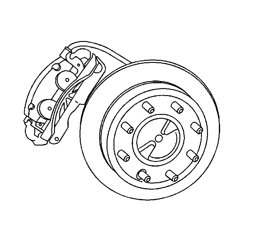
Caution: Support the brake caliper with heavy mechanic wire, or equivalent, whenever it is separated from its mount and the hydraulic flexible brake hose is still connected. Failure to support the caliper in this manner will cause the flexible brake hose to bear the weight of the caliper, which may cause damage to the brake hose and in turn may cause a brake fluid leak.
If equipped with air suspension, the air springs will remain attached to the frame and will not need to be removed.
Installation Procedure
- Install the rear axle assembly to the vehicle.
- Install the coil springs, if equipped. Refer to Coil Spring Replacement.
- Position the bottoms of the rear shocks in the rear axle shock brackets and install the lower shock bolts and nuts.
- Connect the upper control arms to the rear axle. Refer to Rear Axle Upper Control Arm Replacement.
- Connect the lower control arms to the rear axle. Refer to Rear Axle Lower Control Arm Replacement.
- Position the track bar in the bracket and install the bolt and nut.
- Pivot the stabilizer shaft (1) forward and position the insulator brackets to the rear axle.
- Install the stabilizer shaft insulator bracket bolts (2).
- Install the caliper and bracket assemblies to the rear axle.
- Install the electronic locker harness, wheel speed sensor harness, and the brake crossover pipe to the rear axle.
- Install the right-rear park brake cable (2) to the cable guide, the park brake actuator, and the backing plate.
- Install the park brake cable clips (1) to the track bar.
- Connect the left-rear park brake cable (3) to the cable guide, the park brake actuator (2), and the backing plate (1).
- Install the rear propeller shaft. Refer to Rear Propeller Shaft Replacement.
- Connect the rear axle vent tube (1).
- Install the rear tire and wheel assemblies. Refer to Tire and Wheel Removal and Installation.
- Inspect and add axle lubricant, if necessary. Refer to Rear Axle Lubricant Level Inspection.
- Remove the jack stands.
- Lower the vehicle. If equipped with air suspension, ensure the air springs seat properly as the vehicle is being lowered.
- Enable the park brake cable automatic adjuster. Refer to Parking Brake Cable Adjuster Enabling.
- If equipped with air suspension, start the vehicle and run for approximately 2 minutes to ensure the air spring leveling system is functioning properly.
If equipped with air suspension, ensure that the air springs are seated properly on the rear axle.
Caution: Refer to Fastener Caution in the Preface section.
Tighten
Tighten the nuts to 105 N·m (77 lb ft).

Tighten
Tighten the nut to 105 N·m (77 lb ft).

Tighten
Tighten the bolts to 33 N·m (24 lb ft).

Tighten
Tighten the brake caliper bracket bolts to 165 N·m (122 lb ft).

Tighten
Tighten the brake crossover pipe bracket bolt to 22 N·m (16 lb ft).


