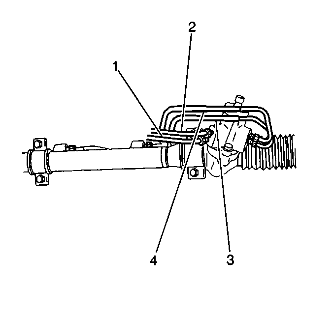
- Perform the following steps in order to install the steering gear
to the vehicle:
| 1.1. | Position the steering gear below the engine compartment. |
| 1.2. | Position the pinion shaft away from the vehicle. |
| 1.3. | Raise the right side of the steering gear in order to position
the steering gear at an angle of 45 degrees. |
| 1.4. | Slide the right side of the steering gear through the right side
frame opening. |
| 1.5. | Raise the left side of the steering gear so that the steering
gear is parallel to the vehicle. |
| 1.6. | Slide the left outer tie rod through the left side frame opening. |
| 1.7. | Rotate the steering gear in order to position the pinion shaft
against the transaxle case. |
| 1.8. | Slide the steering gear slightly to the driver's side. |
Continue to rotate the steering gear.
| 1.9. | Slide the pinion shaft through the floor opening. |
- Install the 2 mounting brackets on the steering gear.
Notice: Use the correct fastener in the correct location. Replacement fasteners
must be the correct part number for that application. Fasteners requiring
replacement or fasteners requiring the use of thread locking compound or sealant
are identified in the service procedure. Do not use paints, lubricants, or
corrosion inhibitors on fasteners or fastener joint surfaces unless specified.
These coatings affect fastener torque and joint clamping force and may damage
the fastener. Use the correct tightening sequence and specifications when
installing fasteners in order to avoid damage to parts and systems.
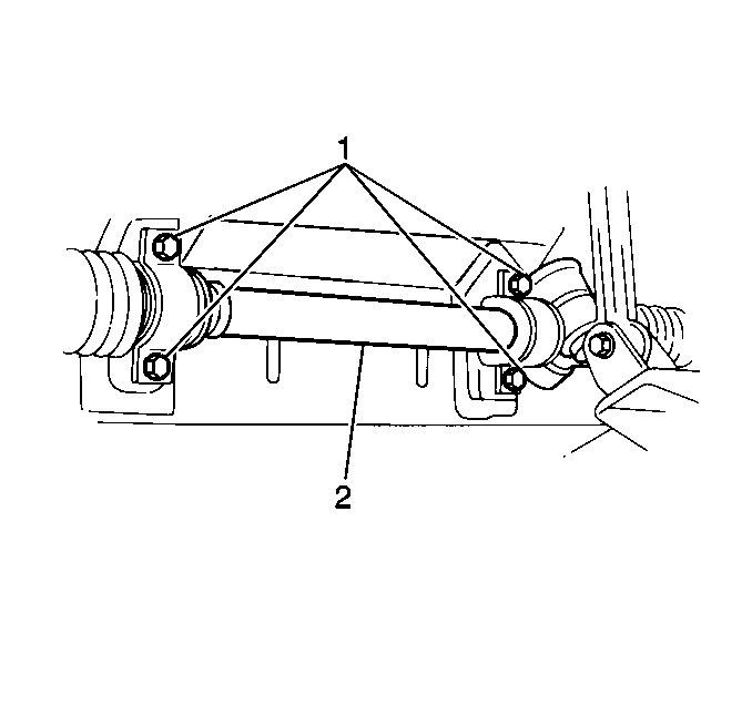
- Secure the steering
gear to the bulkhead with the 4 bolts.
Tighten
Tighten the bolts to 25 N·m (18 lb ft).
- Unplug the steering gear inlet pipe.
- Unplug the steering gear outlet pipe.
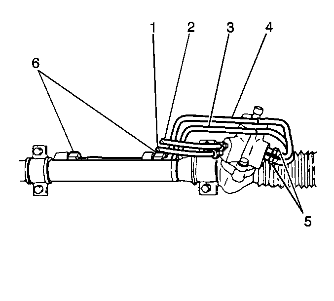
Notice: The inlet and outlet hoses must not be twisted during installation.
Do not bend or distort the inlet or outlet hoses to make installation easier.
Failure to follow these procedures could result in component damage.
- Install the 2 pipes (3, 4) to the steering gear.
- Install the inlet pipe (2) to the steering gear.
- Install the outlet pipe (1) to the steering gear.
Tighten
| • | Tighten the 2 flare nuts (6, 7) to 27 N·m
(19.5 lb ft). |
| • | Tighten the 2 flare nuts (5) to 17 N·m
(12.5 lb ft). |
| • | Tighten the flare nut for the inlet pipe (2) to 40 N·m
(28.5 lb ft). |
| • | Tighten the flare nut for the outlet pipe (1) to 40 N·m
(28.5 lb ft). |
- If the vehicle has a manual transmission, install the gearshift
control shaft and the extension rod. Refer to
Gearshift Control Shaft and Extension Rod Replacement
in Manual Transmission
- M42 and M58.
If the vehicle has an automatic transmission, install the rear torque
rod bracket to the automatic transmission.
- Install the front exhaust pipe to the engine. Refer to
Front Pipe Replacement
in Engine Exhaust.
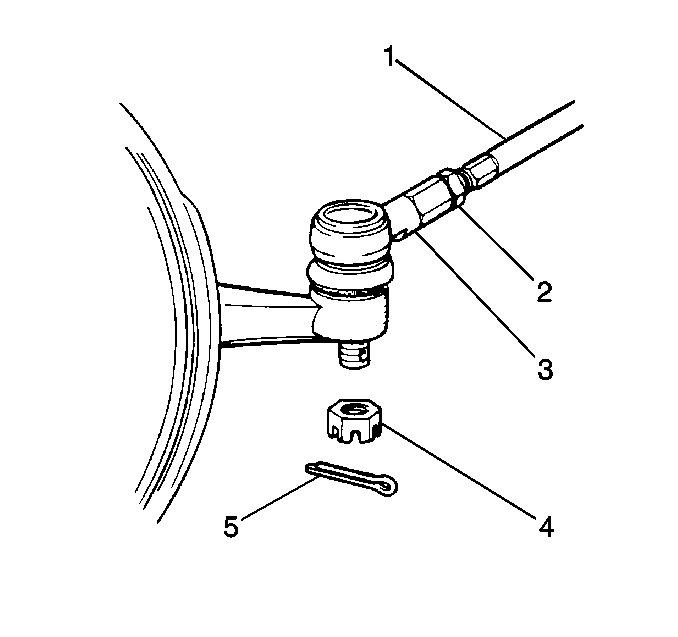
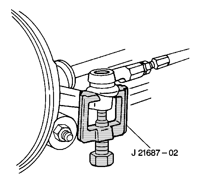
- Install the outer tie
rods (3) to the steering knuckles.
Important: Do not loosen the castle nuts in order to insert the cotter pins.
- Install the castle nuts (4) to the outer tie rods.
Tighten
Tighten the castle nuts to 43 N·m (32 lb ft).
Tighten the castle nut in order to align the cotter pin slot with the ball
stud hole. Do not turn the castle nut more than 1/6 of a turn beyond the
tightening specifications.
- Install the cotter pins (5).
Bend the pin ends in order to secure the castle nuts.
- Install the front tire and wheel assembly. Refer to
Tire and Wheel Removal and Installation
in Tires
and Wheels.
- Lower the vehicle.
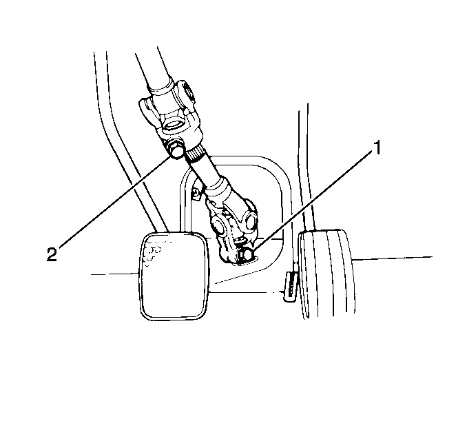
- Install the pinion shaft
to the steering shaft coupling.
- Secure the pinion shaft to the lower steering shaft coupling with
the bolt (1).
Tighten
Tighten the bolt to 25 N·m (18 lb ft).
- Tighten the bolt for the upper steering shaft coupling (2).
Tighten
Tighten the bolt to 25 N·m (18 lb ft).
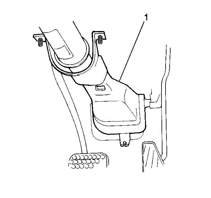
- Install the steering shaft
coupling cover (1).
- Reposition the driver's side floor carpet.
Notice: When adding fluid or making a complete fluid change, always use the
proper power steering fluid. Failure to use the proper fluid will cause hose
and seal damage and fluid leaks.
- Fill the power steering fluid
reservoir with new power steering fluid, if necessary. Refer to
Checking and Adding Power Steering Fluid
.
Notice: If the power steering system has been serviced, an accurate fluid level
reading cannot be obtained unless air is bled from the steering system. The
air in the fluid may cause pump cavitation noise and may cause pump damage
over a period of time.
- Bleed the power steering system.
Refer to
Power Steering System Bleeding
.
- Measure the wheel alignment. Refer to
Wheel Alignment Measurement
in Wheel Alignment.
- Adjust the front toe, if necessary. Refer to
Front Toe Adjustment
in Wheel Alignment.


