Cylinder Head Replacement Left
Special Tools
J 36660-A Torque Angle Meter
Removal Procedure
- Recover the refrigerant. Refer to refrigerant in Heater, Ventilation and Air Conditioning.
- Lower he intake manifold. Refer to Lower Intake Manifold Replacement .
- Remove the crossover pipe. Refer to Crossover Pipe in Exhaust System.
- Remove the spark plug wires from the spark plugs. Refer to Spark Plug Wire in Ignition System.
- Remove the rocker arm covers. Refer to Valve Rocker Arm Cover Replacement .
- Remove the rocker arms. Refer to Valve Rocker Arm and Push Rod Replacement .
- Remove the pushrods. Refer to Valve Rocker Arm and Push Rod Replacement .
- Remove the oil level indicator and tube. Refer to Oil Level Indicator and Tube Replacement .
- Remove the A/C compressor bolts from the top. Refer to Heater, Ventilation and Air Conditioning.
- Remove the A/C lines from the rear of the compressor. Refer to Heater, Ventilation and Air Conditioning.
- Raise and support the vehicle. Refer to vehicle support in General Information.
- Remove the wiring harness connector from the rear of the compressor. Refer to Heater, Ventilation and Air Conditioning.
- Remove the A/C compressor lower bracket bolts. Refer to Heater, Ventilation and Air Conditioning.
- Lower the vehicle.
- Remove the A/C compressor upper bracket bolts. Refer to Heater, Ventilation and Air Conditioning.
- Remove the compressor brackets. Refer to Heater, Ventilation and Air Conditioning.
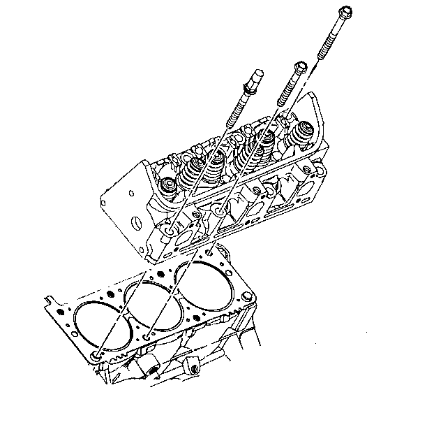
- Remove and discard the cylinder head bolts.
- Remove the cylinder head and gasket.
- Clan the following items:


| • | The cylinder head. carefully remove all varnish, soot and carbon to the bare metal. Do not use a motorized wire brush on any gasket sealing surfaces. |
| • | The cylinder block bolt threads |
Installation Procedure
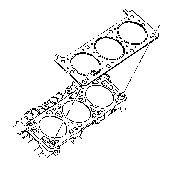
- Place the gasket in position over the dowel pins, with the note "this side up" showing.
- Install the cylinder head.
- Install the NEW cylinder head bolts.
- Install the compressor brackets. Refer to Heater, Ventilation and Air Conditioning.
- Install the A/C compressor upper bracket bolts. Refer to Heater, Ventilation and Air Conditioning.
- Raise and support the vehicle. Refer to vehicle support in General Information.
- Install the A/C compressor lower bracket bolts. Refer to Heater, Ventilation and Air Conditioning.
- Install the wiring harness connector from the rear of the compressor. Refer to Heater, Ventilation and Air Conditioning.
- Install the A/C compressor
- Install the A/C lines to the rear of he compressor with new sealing washers. Refer to Heater, Ventilation and Air Conditioning.
- Install the compressor top bolts. Refer to Heater, Ventilation and Air Conditioning.
- Install the oil level indicator and fill tube. Refer to Oil Level Indicator and Tube Replacement .
- Install the pushrods. Valve Rocker Arm and Push Rod Replacement .
- Install the rocker arms. Valve Rocker Arm and Push Rod Replacement .
- Install the rocker arm covers. Valve Rocker Arm Cover Replacement .
- Install the spark plug wires to the spark plugs. Refer to Spark Plug Wire in Ignition System.
- Install the crossover pipe. Refer to Crossover Pipe in Exhaust System.
- Lower the intake manifold. Refer to Lower Intake Manifold Replacement .
- Evacuate and charge the A/C system. Refer to Heater, Ventilation and Air Conditioning.
- Leak test the A/C system. Refer to Heater, Ventilation and Air Conditioning.
- Inspect for proper fluid levels and leaks.


Notice: This component uses torque-to-yield bolts. When servicing this component do not reuse the bolts, New torque-to-yield bolts must be installed. Reusing used torque-to-yield bolts will not provide proper bolt torque and clamp load. Failure to install NEW torque-to-yield bolts may lead to engine damage.
Notice: Use the correct fastener in the correct location. Replacement fasteners must be the correct part number for that application. Fasteners requiring replacement or fasteners requiring the use of thread locking compound or sealant are identified in the service procedure. Do not use paints, lubricants, or corrosion inhibitors on fasteners or fastener joint surfaces unless specified. These coatings affect fastener torque and joint clamping force and may damage the fastener. Use the correct tightening sequence and specifications when installing fasteners in order to avoid damage to parts and systems.
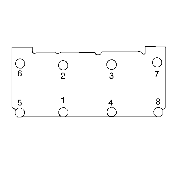
Tighten
Tighten the bolts to 60 N·m (44 lb ft) plus an additional 95 degrees using a
J 36660-A
.
Important: It is recommended that the engine oil be drained and the crankcase refilled with clean engine oil to avoid possible contamination by the engine coolant and/or foreign material when removing the cylinder head.
Cylinder Head Replacement Right
Removal Procedure
Special Tools
J 36660-A Torque Angle Meter
- Remove the lower intake manifold. Refer to Lower Intake Manifold Replacement .
- Disconnect the ignition coil connection. Refer to Ignition Coil .
- Remove the generator. Refer to Generator Replacement .
- Remove the crossover pipe. Refer to Exhaust Crossover Replacement .
- Remove the oxygen sensor. Refer to Heated Oxygen Sensor Replacement .
- Raise and suitably support the vehicle. Refer to General Information.
- Remove the exhaust pipe from the manifold. Refer to Exhaust Pipe Replacement .
- Lower the vehicle.
- Remove the valve rocker arms and the pushrods. Refer to Valve Rocker Arm and Push Rod Replacement .
- Remove and discard the cylinder head bolts.
- Remove the cylinder head.
- Remove the cylinder head gasket.
- Clean the following components:
- Inspect the cylinder head. Refer to Cylinder Head Cleaning and Inspection .


| • | Clean the cylinder head. Carefully remove all varnish, soot, and carbon to the bare metal. DO NOT use a motorized wire brush on any gasket sealing surfaces. |
| • | Clean the cylinder block bolt threads. |
Installation Procedure
- Place the gasket in position over the dowel pin with the note THIS SIDE UP showing.
- Install the cylinder head.
- .
- Install the NEW cylinder head bolts.
- Install the pushrods and the rocker arms. Refer to Valve Rocker Arm and Push Rod Replacement .
- Raise and suitably support the vehicle. Refer to General Information.
- Install the exhaust pipe to the manifold. Refer to Exhaust Pipe Replacement .
- Lower the vehicle.
- Install the oxygen sensor. Refer to Heated Oxygen Sensor Replacement .
- Install the crossover pipe. Refer to Exhaust Crossover Replacement .
- Install the generator. Refer to Generator Replacement .
- Connect the ignition coil connections. Refer to Ignition Coil .
- Install the lower intake manifold. Refer to Lower Intake Manifold Replacement .
- Inspect the engine for proper fluid levels.
- Inspect the engine for leaks.


Notice: This component uses torque-to-yield bolts. When servicing this component do not reuse the bolts, New torque-to-yield bolts must be installed. Reusing used torque-to-yield bolts will not provide proper bolt torque and clamp load. Failure to install NEW torque-to-yield bolts may lead to engine damage.
Notice: Use the correct fastener in the correct location. Replacement fasteners must be the correct part number for that application. Fasteners requiring replacement or fasteners requiring the use of thread locking compound or sealant are identified in the service procedure. Do not use paints, lubricants, or corrosion inhibitors on fasteners or fastener joint surfaces unless specified. These coatings affect fastener torque and joint clamping force and may damage the fastener. Use the correct tightening sequence and specifications when installing fasteners in order to avoid damage to parts and systems.
Tighten
Tighten the bolts in sequence to 60 N·m (44 lb ft) plus an additional 95 degrees using
J 36660-A
.
Important: It is recommended that the engine oil be drained and the crankcase refilled with clean oil to avoid possible contamination by the engine coolant and/or foreign material when removing the cylinder head.
