Removal Procedure
- Remove the folding top and place the top upside down on a clean flat surface. Refer to Folding Top Replacement .
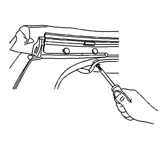
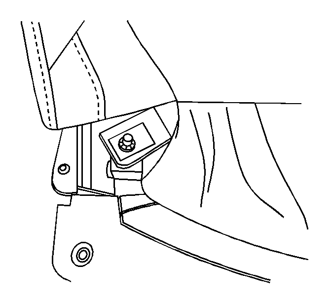
- Remove the following components from the rear side rail.
- Remove the headliner screw from the #1 bow.
- Remove the headlining push-on retainers from the #1 bow.
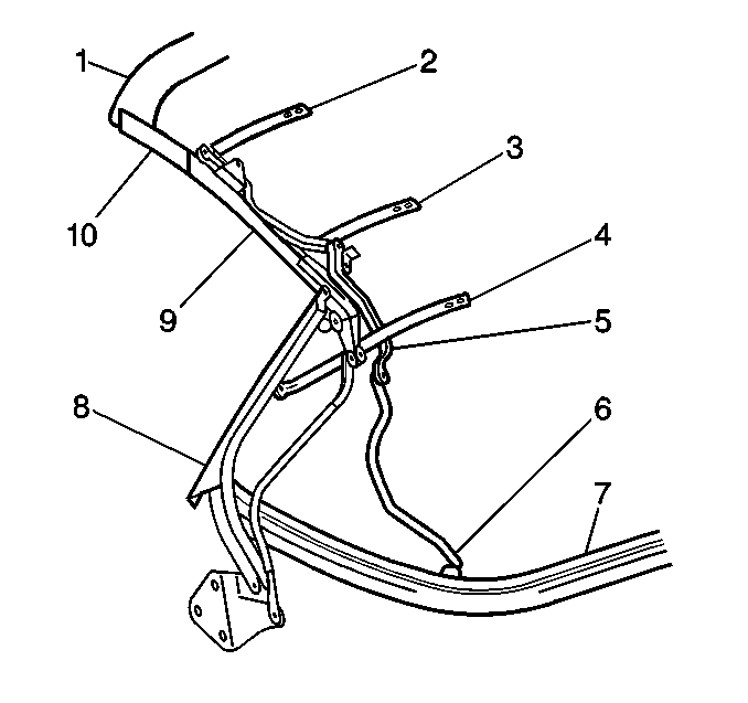
- Remove the main control link bracket screws from the #2 bow (2).
- Remove the main control link bracket screws from the #3 bow (3).
- Remove the main control link bracket screws from the #4 bow (4).
- Using a grease pencil mark the end position of the adjustable link rod as an aid in assembling a new part.
- Remove the screw (6) from the end of the main control link rod on the #5 bow (7).
- Remove the screw from the main control link on the center side rail.
- Remove the screw from the main control link on the front side rail.
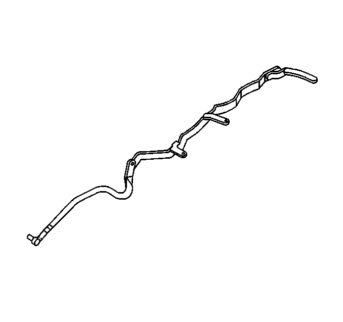
- Remove the main control link.
| 2.1. | The headliner screws |
| 2.2. | The glare cover elastic strap screws |
| 2.3. | The headliner elastic strap screws |


Installation Procedure
- Position the main control link to the top.
- Install the spacers and the screw attaching the main control link to the front side rail.
- Install the spacers and the screw attaching the main control link to the center side rail.
- Adjust the end of the link adjuster (6) rod to match the marked position.
- Install the end screw to the main control link rod on the #5 bow (7).
- Install the screws to the control link brackets on the #2, 3, and 4 roof bows.
- Install the headliner push-on retainers to the #1 bow.
- Install the attaching the headliner screws to the #1 bow.
- Install the glare cover to the #5 bow.
- Install the headliner screw to the rear side rail.
- Install the headliner elastic strap screw to the rear side rail.
- Install the folding top. Refer to Folding Top Replacement .
- Reposition the folding top to the original position.

Notice: Use the correct fastener in the correct location. Replacement fasteners must be the correct part number for that application. Fasteners requiring replacement or fasteners requiring the use of thread locking compound or sealant are identified in the service procedure. Do not use paints, lubricants, or corrosion inhibitors on fasteners or fastener joint surfaces unless specified. These coatings affect fastener torque and joint clamping force and may damage the fastener. Use the correct tightening sequence and specifications when installing fasteners in order to avoid damage to parts and systems.
Tighten
Tighten the screw to 20 N·m (15 lb ft).
Tighten
Tighten the screw to 20 N·m (15 lb ft).

Tighten
Tighten the screw to 15 N·m (11 lb ft).
Tighten
Tighten the screws to 13 N·m (9 lb ft).


Tighten
Tighten the screws to 2 N·m (18 lb in).
Tighten
Tighten the screw to 2 N·m (18 lb in).
Tighten
Tighten the screw to 2 N·m (18 lb in).
Tighten
Tighten the screw to 2 N·m (18 lb in).
