Steering Shaft, Lower Bearing, and Jacket - Assemble - Off Vehicle Telescoping Column
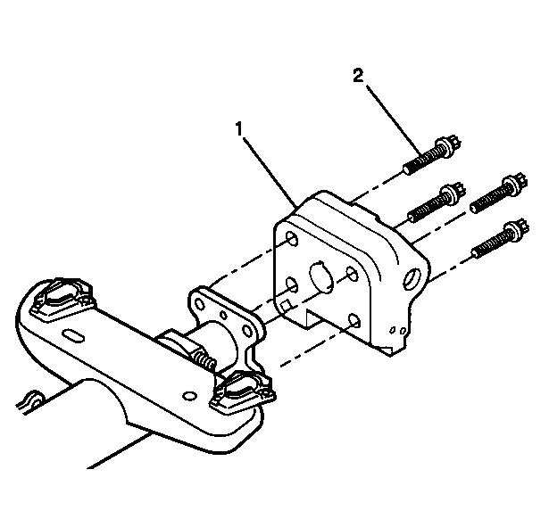
- Install the steering column support assembly (1) to the telebearing and jacket assembly.
- Install the 4 TORX® screws (2).
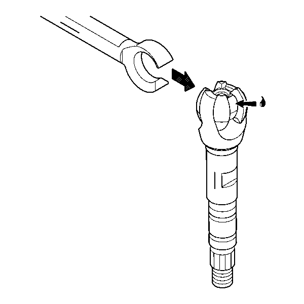
- Apply lithium grease to the exposed shaft engagement areas on the centering sphere.
- Install the lower steering shaft assembly to the race and upper shaft assembly to engage.
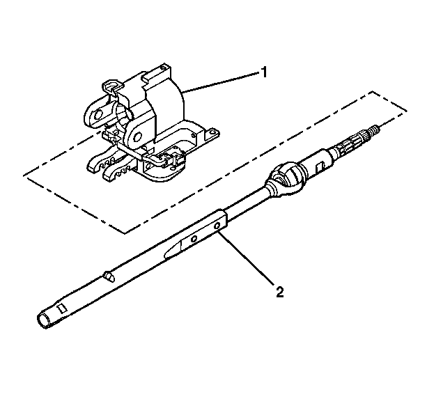
- Install the steering shaft assembly (2) into the steering column tilt head assembly (1).
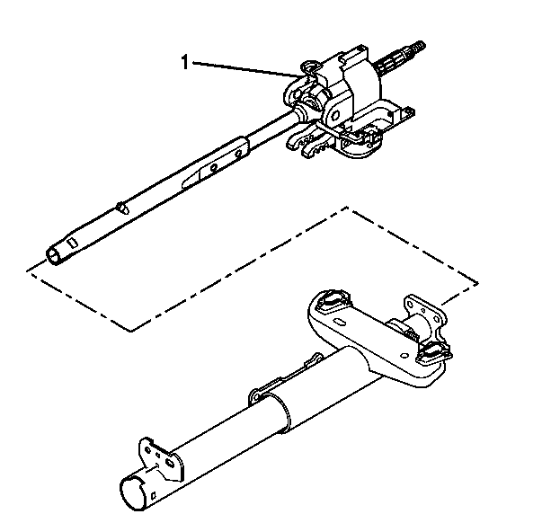
- Install the steering column tilt head assembly (1) and the steering shaft assembly to the telebearing and jacket assembly.
- Install the 2 pivot pins (1) to the steering column support assembly.
- Stake the pivot pins locations (1).
- Install the adapter and bearing assembly (1) to the steering shaft assembly.
- Install the lower spring retainer (2) to the adapter and bearing assembly (1).
- Install the dual triangle sensor assembly (3) onto the steering shaft assembly.
- Install the steering shaft seal (1).
- Install the telescope actuator assembly. Refer to Telescope Actuator Assembly - Assemble - Off Vehicle .
- Install the telescope motor assembly. Refer to Telescope Motor Assembly - Assemble - Off Vehicle .
- Install the tilt spring only. Refer to Tilt Spring - Assemble - Off Vehicle .
- Install the signal switch housing. Refer to Turn Signal Switch Housing - Assemble - Off Vehicle .
- Enable the inflatable restraint steering wheel module. Refer to Enabling the SIR System in SIR.
Important: Replace the steering column support assembly if the steering column support assembly has been staked 3 times.
Notice: Use the correct fastener in the correct location. Replacement fasteners must be the correct part number for that application. Fasteners requiring replacement or fasteners requiring the use of thread locking compound or sealant are identified in the service procedure. Do not use paints, lubricants, or corrosion inhibitors on fasteners or fastener joint surfaces unless specified. These coatings affect fastener torque and joint clamping force and may damage the fastener. Use the correct tightening sequence and specifications when installing fasteners in order to avoid damage to parts and systems.
Tighten
Tighten the screws to 17 N·m (13 lb ft).
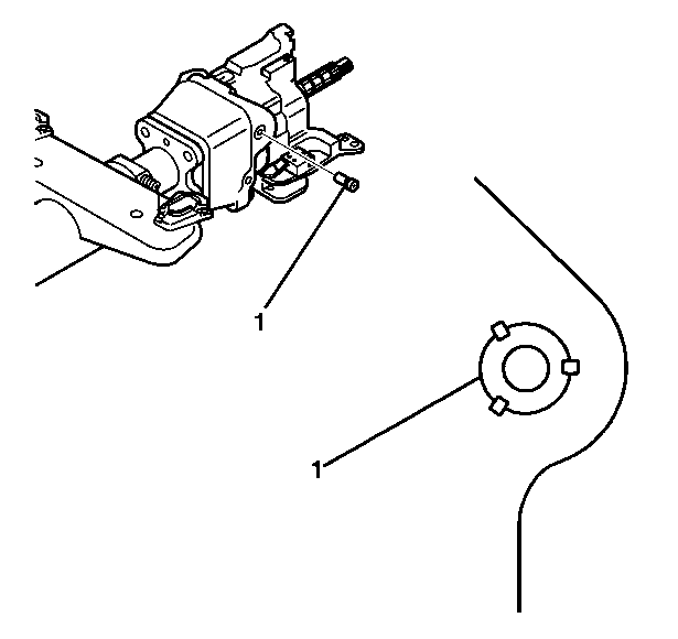
Important: Replace the steering column support assembly if the steering column support assembly has been staked 3 times.
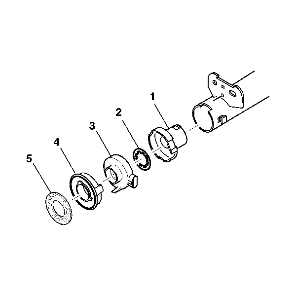
Important: Rotate the steering shaft assembly to the 12 o'clock position.
Install the sensor retainer (4) and seal (5) onto the steering shaft assembly.
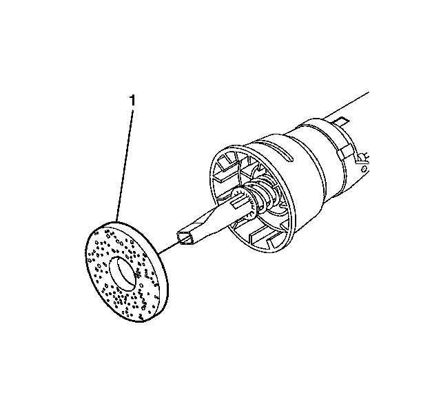
Caution: Improper routing of the wire harness assembly may damage the inflatable restraint steering wheel module coil. This may result in a malfunction of the coil, which may cause personal injury.
Steering Shaft, Lower Bearing, and Jacket - Assemble - Off Vehicle Non-Telescoping
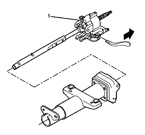
- Install the steering column support assembly (1) to the steering column jacket assembly (3).
- Install the 4 TORX® head screws (2).
- Apply lithium grease to the exposed shaft engagement areas on the centering sphere.
- Install the lower steering shaft assembly to the race and upper shaft assembly to engage.
- Install the steering shaft assembly (2) into the steering column tilt head assembly (1).
- Install the steering column tilt head assembly (1) and the steering shaft assembly to the steering column jacket assembly.
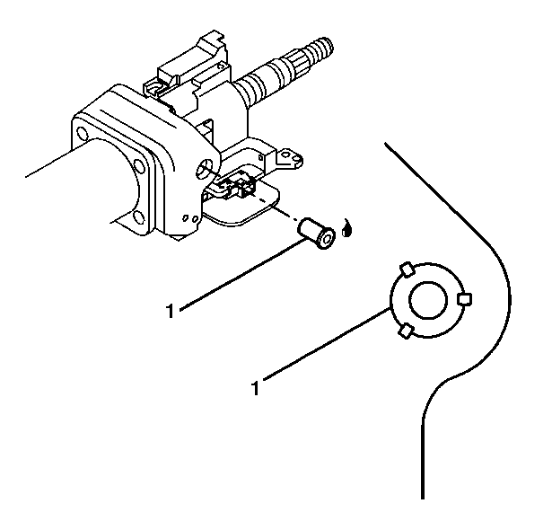
- Install the 2 pivot pins (1) to the steering column support assembly.
- Stake the pivot pins locations (1).
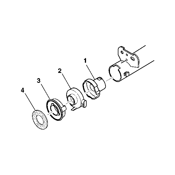
- Install the adapter and bearing assembly (1) to the steering shaft assembly.
- Install the dual triangle sensor assembly (2) onto the steering shaft assembly.
- Install the sensor retainer (3) onto the steering shaft assembly.
- Install the steering shaft seal (4).
- Install the signal switch housing. Refer to Turn Signal Switch Housing - Assemble - Off Vehicle .
- Install the tilt spring. Refer to Tilt Spring - Disassemble - Off Vehicle .
- Enable the inflatable restraint steering wheel module. Refer to Enabling the SIR System in SIR.
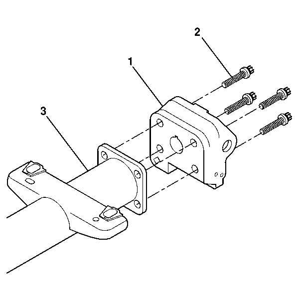
Important: Replace the steering column support assembly if the steering column support assembly has been staked 3 times.
Notice: Use the correct fastener in the correct location. Replacement fasteners must be the correct part number for that application. Fasteners requiring replacement or fasteners requiring the use of thread locking compound or sealant are identified in the service procedure. Do not use paints, lubricants, or corrosion inhibitors on fasteners or fastener joint surfaces unless specified. These coatings affect fastener torque and joint clamping force and may damage the fastener. Use the correct tightening sequence and specifications when installing fasteners in order to avoid damage to parts and systems.
Tighten
Tighten the 4 TORX® head screws to 17 N·m (13 lb ft).


Important: Replace the steering column support assembly if the steering column support assembly has been staked 3 times.
Important: The steering shaft assembly must be rotated to the 12 o'clock position.
