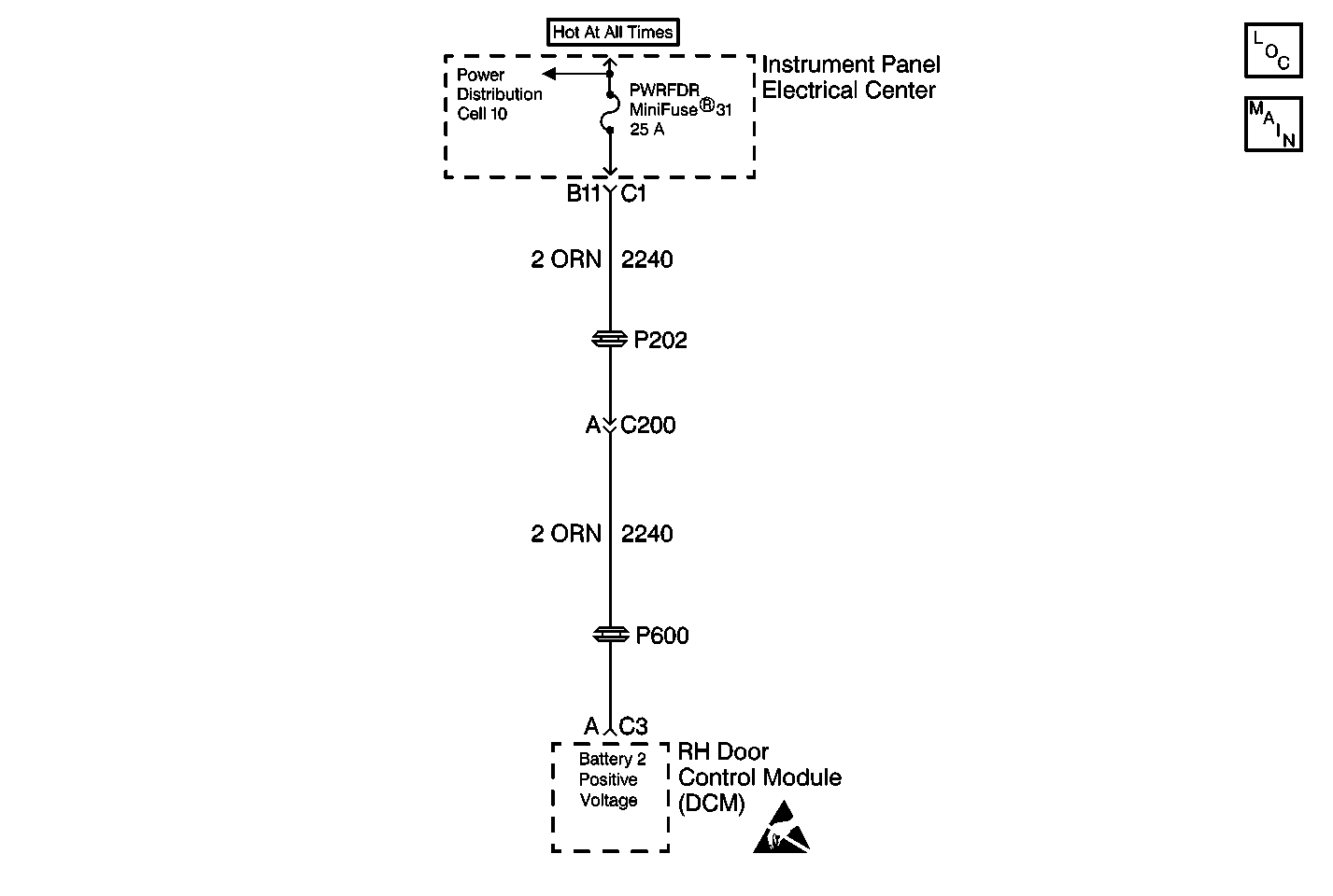
Circuit Description
The RH Door Control Module (RDCM) has two main power feeds (high and low), and one main ground. The low power feed (battery 1) is used to provide power for the RDCM logic and internal driver operation. The high power feed (battery 2) is used to provide power for systems that draw higher amounts of current (motors, lights etc.). For most functions, the RDCM will operate properly when vehicle system voltage is between 9.0-16.0 volts. The RDCM also monitors the voltage level at battery 1 and battery 2 circuits and can determine if the voltage level received is out of range. If the voltage level is out of range in either circuit , then a malfunction is present and a DTC will set.
Conditions for Setting the DTC
| • | The RDCM detects battery 1 voltage range under 8.5 volts or over 16.3 volts. |
| • | Condition must be present for 2 seconds. |
Action Taken When the DTC Sets
| • | Stores a history DTC B2285 in the RDCM memory. |
| • | This DTC can only be set as a history code even if the malfunction is current. |
| • | No driver warning message will be displayed for this DTC. |
Conditions for Clearing the DTC
| • | The RDCM detects battery 2 voltage range between 8.5-16.3 volts for longer than 2 seconds. |
| • | Use the IPC clearing DTCs feature. |
| • | Use a scan tool. |
Diagnostic Aids
| • | The following conditions may cause an intermittent malfunction: |
| - | There is an intermittent open or short to ground in the battery 2 circuit (CKT 2240). |
| - | The battery voltage is not within range (8.5-16.3 volts). |
| - | A charging system malfunction. |
| • | Using a scan tool, select RDCM Data display and monitor battery 2 voltage while operating different devises (windows, door locks, power mirrors, etc.). This can determine if battery 2 voltage is affected by these devises and can help duplicate the malfunction. |
| • | If the DTC does not reset after the code is cleared, then the problem may be intermittent. Perform the tests shown while moving related wiring and connectors. This can often cause the malfunction to occur. Refer to Intermittents and Poor Connections . |
Test Description
The numbers below refer to the step numbers on the diagnostic table:
-
This test checks if the vehicle's Starting/Charging system is functioning properly. Starting/Charging system malfunctions will cause the RDCM to store a history DTC B2285, therefore always repair all Starting/Charging malfunctions first.
-
This test checks the battery 2 voltage using a scan tool. Normal battery 2 voltage range is between 8.5-16.3 volts.
-
This test checks the instrument panel electrical center and CKT 2240 for an open or short to ground. Normal battery 2 voltage range is between 8.5-16.3 volts.
-
This test checks for any other history DTC stored in the RDCM memory that may cause a DTC B2285 to set.
Step | Action | Value(s) | Yes | No | ||||||||
|---|---|---|---|---|---|---|---|---|---|---|---|---|
1 | Were you sent here from the Power Door Diagnostic System Check? | -- | ||||||||||
Verify that the vehicle's Starting/Charging system is functioning properly. Repair any current Starting/Charging malfunctions. Refer to Charging System Check in Engine Electrical. Is the Starting/Charging system functioning properly? | -- | Go to Charging System Check | ||||||||||
Using a scan tool, select RDCM data display and monitor battery 2 data. Does the scan tool display battery 2 voltage within the specified range? | 8.5-16.3 V | |||||||||||
Is the voltage within the specified range? | 8.5-16.3 V | |||||||||||
Using a scan tool, select RDCM DTC display and check for the following DTCs stored as history:
Are any of this DTCs stored as history? | -- | Go to the Applicable DTC Table | ||||||||||
6 | Locate and repair an open or short to ground in the instrument panel electrical center or CKT 2240. Is the circuit repair complete? | -- | -- | |||||||||
7 |
Is the replacement complete? | -- | -- | |||||||||
8 | Check the battery 2 circuit for an intermittent malfunction. Refer to Diagnostic Aids. Was a problem found and repaired? | -- | ||||||||||
9 |
Does DTC B2285 set as history? | -- | System OK | |||||||||
10 |
Is the repair complete? | -- | -- |
