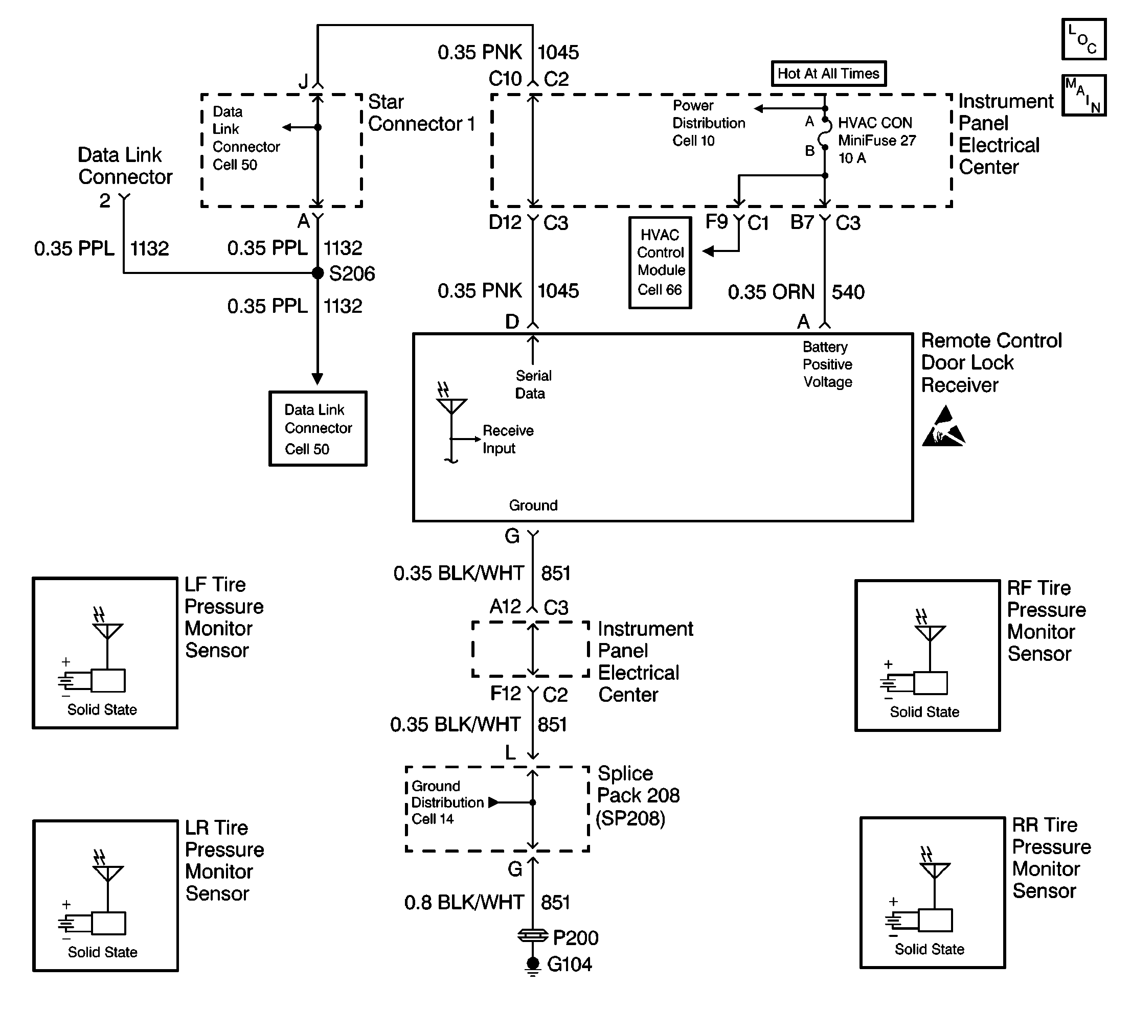
Circuit Description
The Tire Pressure Monitor (TPM) Diagnostic System Check is an organized approach to identify problems associated with the TPM system. This check must be the starting point for any TPM complaint, and will direct you to the next logical step in diagnosing the complaint. The TPM uses the same receiver as the Remote Function Actuation (RFA) system. Therefore, when a TPM malfunction occurs, all diagnostic information (DTCs, input data, etc.) must be accessed through the RFA system.
Diagnostic Aids
| • | The following conditions may result in an intermittent operation of the TPM system with no DTC stored: |
| - | Any condition which results in the interruption of power to the receiver |
| - | Over or underinflated tires |
| - | Out-of-range battery or ignition voltage |
Specification
Normal battery or ignition voltage: 9.0-16.0 V
| - | A loose or damaged ground(s) |
| - | An open or shorted serial data line |
| • | An intermittent failure in the electronic system may be very difficult to detect and to accurately diagnose. The TPM tests for different malfunctions under different vehicle conditions. For this reason, a thorough test drive is often needed in order to repeat a fault condition. If the system malfunction is not repeated during the test drive, a good description of the complaint may be very useful in locating an intermittent malfunction. Faulty electrical connections or wiring causes most intermitting problems. When an intermitting condition is suspected, check the suspected circuits for the following conditions: |
| - | Poor mating of connector halves or backed out terminals |
| - | Improperly formed or damaged terminals |
| - | Wire chafing |
| - | Poor wire to terminal connections |
| - | Dirty or corroded terminals |
| - | Damage to connector bodies |
| • | When a TPM system malfunction is corrected, clear the receiver's diagnostic memory before road testing the vehicle in order to avoid reading the original DTC stored in the memory. |
Test Description
The numbers below refer to the step numbers on the diagnostic table:
-
This test determines if communications can be established with the RFA system.
-
This test checks for communication DTCs stored in the RFA system (communication DTCs begin with the letter U). Communication DTCs must be diagnosed and corrected first before diagnosing any other DTCs.
-
This test checks for any TPM system DTCs stored in the receiver's memory.
-
This test checks for any RFA system DTCs stored in the receiver's memory. Some DTCs that are associated with the RFA system may cause a TPM system malfunction. Always diagnosis any RFA DTCs that are stored.
-
This test checks the IPC for any TPM system warning messages.
-
This test determines if communications can be established with other subsystems connected to the same serial data line.
-
This test checks the receiver's power circuit. If the test light does not go ON, there is an open in CKT 540.
-
This test checks the receiver's ground circuit. If the test light does not go ON, there is an open in CKT 851.
-
This test determines if there is an open in the serial data line between the receiver and the DLC terminal (CKT 1045).
Step | Action | Value(s) | Yes | No | ||||||||
|---|---|---|---|---|---|---|---|---|---|---|---|---|
Does the scan tool communicate with the RFA system? | -- | |||||||||||
Are any communication DTCs stored? | -- | |||||||||||
Check for any TPM DTCs stored in the RFA system. Refer to Diagnostic Trouble Code (DTC) List/Type . Are any of these DTCs stored? | -- | Go to Applicable DTC Table | ||||||||||
Check for any RFA DTCs. Refer to Diagnostic Trouble Code (DTC) List/Type . Are any of these DTCs stored? | -- | |||||||||||
Are any of these messages displayed? | -- | System OK | ||||||||||
Attempt to establish communications with the other systems connected to the same serial data line (PCM, BCM, ABS, IPC, etc.). Does the scan tool communicate with any other system? | -- | |||||||||||
Does the test light turn ON? | -- | |||||||||||
With a test light connected to B+, probe the RFA receiver ground terminal G (harness side). Does the test light turn ON? | -- | |||||||||||
Check for continuity between the RFA receiver connector terminal D (harness side) and the DLC connector terminal 2. Is there continuity? | -- | |||||||||||
10 |
Is the replacement complete? | -- | -- | |||||||||
11 |
Is the repair complete? | -- | -- | |||||||||
12 | Locate and repair the open in the serial data line (CKT 1045). Is the repair complete? | -- | -- | |||||||||
13 | Locate and repair the open in the receiver ground circuit (CKT 851). Is the repair complete? | -- | -- | |||||||||
14 |
Are all DTCs cleared? | -- | System OK | -- |
