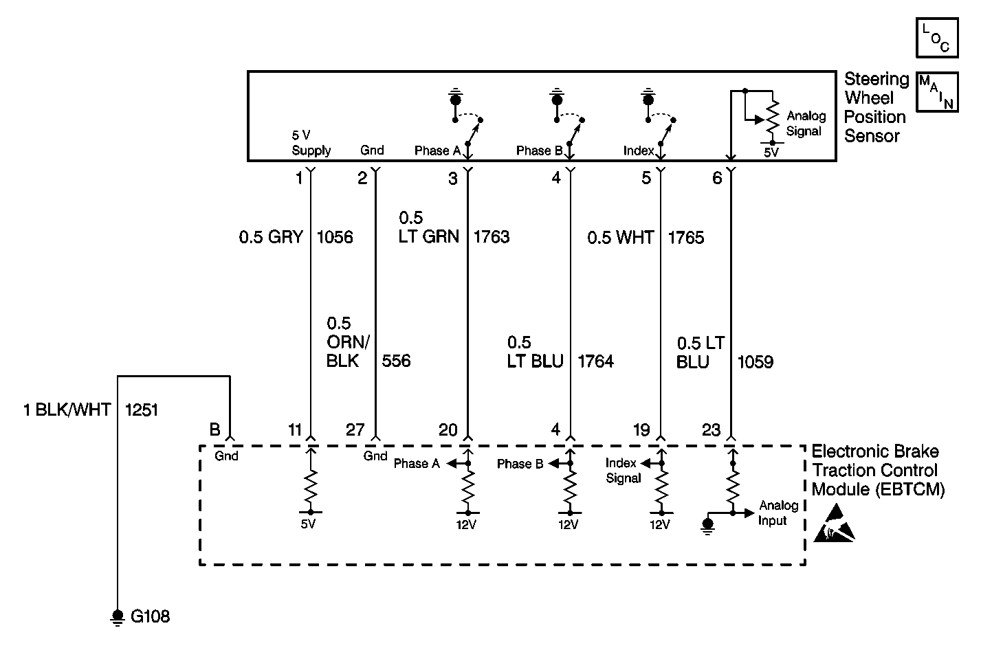
DTC C1286 Steering Sensor Bias Malfunction DTC C1286 (Without RPO JL4)

Circuit Description
The EBTCM runs a centering routine when the vehicle speed goes above 30 Km/h (18 mph). When the vehicle reaches 30 Km/h (18 mph), the EBTCM monitors the Steering Wheel Position Sensor inputs (Phase A, Phase B and Analog voltage) to see if the steering wheel is moving. If the steering wheel is not moving for a set period of time then the EBTCM assumes the vehicle is going in a straight line. At this point, the EBTCM looks at the analog voltage signal and reads the voltage. This voltage normally around 2.5V, is then considered the center position and the digital degrees also become zero at the same time. This centering routine is necessary to compensate for wear in the steering and suspension. Wear in the steering and suspension can result in a change in the relationship between the steering wheel and the front wheels. By running the centering routine the EBTCM can compensate for these changes by changing the digital and analog center position.
Conditions for Setting the DTC
| • | DTC C1286 can be set after the centering routines completion if the bias value is ± 30 degrees from the previous bias value. |
| • | DTC C1286 can also be set at start up if the bias value was out of range on the last ignition cycle. |
Action Taken When the DTC Sets
Magnasteer®2 is disabled, ABS/TCS remains active.
Messages displayed on the DIC:
Service Vehicle Soon
Conditions for Clearing the DTC
| • | Condition for DTC is no longer present and scan tool clear DTC function is used. |
| • | Fifty ignition cycles have passed with no DTCs detected. |
Diagnostic Aids
Possible causes:
| • | Steering wheel rotated with steering gear disconnected. |
| • | Check connector C102 RH side rear of engine compart for water intrusion or missing plugs, and that the connector is oriented horizontal to prevent water intrusion. Check for a faulty Steering Wheel Position Sensor. |
| • | Faulty EBTCM. |
Test Description
The numbers below refer to the step numbers on the diagnostic table.
Step | Action | Value(s) | Yes | No |
|---|---|---|---|---|
1 | Was the Diagnostic System Check performed? | -- | ||
2 | Is this vehicle equipped with Active Handling (RPO JL4)? | -- | Go to DTC C1286 Steering/Lateral Accelerometer Sensor Bias Malfunction | |
3 |
Is the voltage within the range specified within the value(s) column? | 2-3 V | ||
4 | Using a scan tool, perform the Steering Wheel Position Sensor Test. Refer to Scan Tool Diagnostics. Are the analog and digital displays on the scan tool within plus or minus 5 degrees of each other at the center (zero) position? | -- | ||
5 | Replace the EBTCM. Refer to Electronic Brake Control Module Replacement . Is the repair complete? | -- | -- | |
Does the analog voltage move to or close to 2.5 volts? | -- | |||
7 | Replace the Steering Wheel Position Sensor. Refer to Steering Shaft, Lower Bearing, and Jacket - Disassemble - Off Vehicle in Steering Wheel and Column. Is the replacement complete? | -- | ||
8 |
Is the repair complete? | -- | -- | |
9 |
Did DTC C1286 set as a current DTC? | -- |
