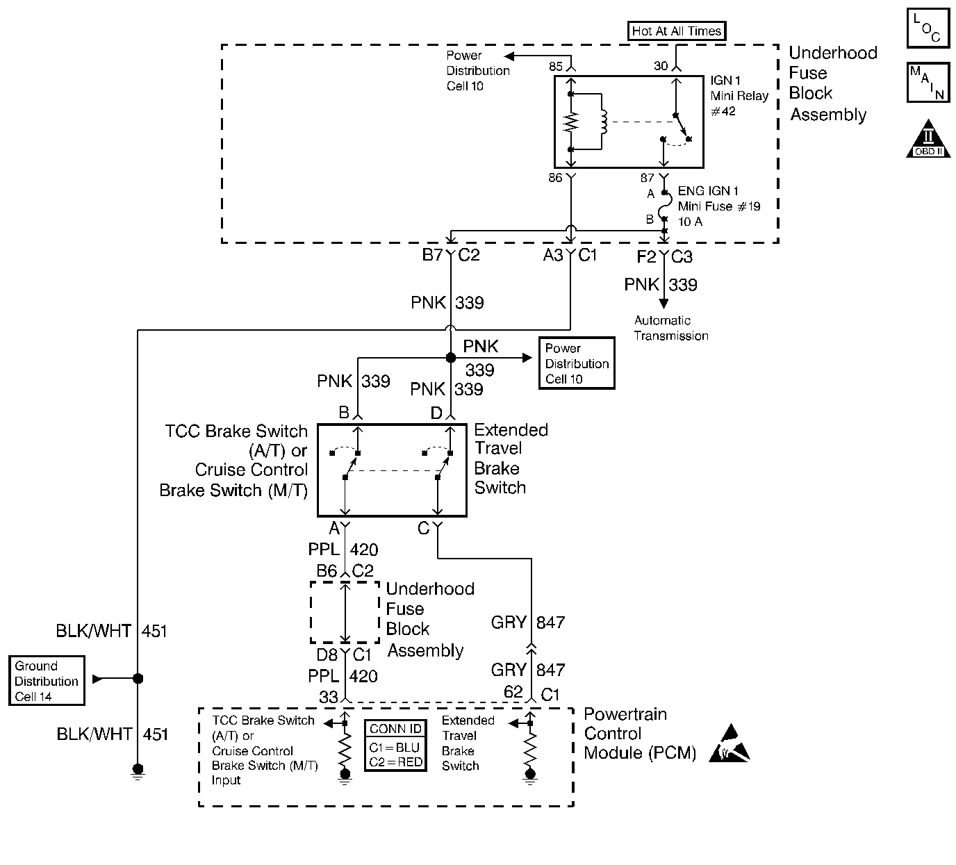
Circuit Description
The Cruise Control Brake switch is a normally closed switch. When the Cruise Control Brake switch is closed, (brake pedal released) the PCM senses ignition voltage on the Cruise Control Brake switch signal circuit.
If the PCM senses a voltage on the Cruise Control Brake switch signal circuit when the Cruise Control Brake switch should be open, this DTC sets.
Conditions for Running the DTC
| • | The engine speed is greater than 700 RPM. |
| • | The engine operates for greater than 2 seconds. |
| • | The wheel speed is greater than 30 mph in order to enable the diagnostic. The diagnostic disables when the wheel speed is below 10 mph. |
Conditions for Setting the DTC
| • | The PCM detects voltage on the Cruise Control Brake switch circuit when the Cruise Control Brake switch should be open. |
| • | All above conditions are present for 1.5 seconds. |
Action Taken When the DTC Sets
| • | The powertrain control module (PCM) stores the DTC information into memory when the diagnostic runs and fails. |
| • | The malfunction indicator lamp (MIL) will not illuminate. |
| • | The PCM records the operating conditions at the time the diagnostic fails. The PCM stores this information in the Failure Records. |
Conditions for Clearing the DTC
| • | A last test failed, or current DTC, clears when the diagnostic runs and does not fail. |
| • | A history DTC will clear after 40 consecutive warm-up cycles, if no failures are reported by this or any other non-emission related diagnostic. |
| • | Use a scan tool in order to clear the DTC. |
Diagnostic Aids
Important:
• Remove any debris from the PCM\TAC module connector surfaces before
servicing the PCM\TAC module. Inspect the PCM\TAC module connector gaskets
when diagnosing/replacing the modules. Ensure that the gaskets are installed
correctly. The gaskets prevent contaminate intrusion into the PCM\TAC
modules. • For any test that requires probing the PCM or a component
harness connector, use the Connector Test Adapter Kit J 35616
. Using this kit prevents damage
to the harness/component terminals. Refer to
Using Connector Test Adapters
in Wiring Systems.
| • | Test drive the vehicle if a switch or circuit condition cannot be located. An intermittent condition may be duplicated during a test drive. |
| • | For the Cruise Control Brake switch adjustment refer to Stop Lamp Switch Adjustment in Hydraulic Brakes. |
| • | For an intermittent, refer to Symptoms . |
Test Description
The numbers below refer to the step numbers on the diagnostic table.
-
This step determines if the fault is present.
-
This step checks for a Cruise Control Brake Switch circuit for being shorted to B+.
Step | Action | Value(s) | Yes | No |
|---|---|---|---|---|
1 | Did you perform the Powertrain On-Board Diagnostic (OBD) System Check? | -- | ||
Does the scan tool display indicate Applied? | -- | Go to Diagnostic Aids | ||
3 | Check the adjustment of the cruise control brake switch. Refer to Diagnostic Aids . Did you perform an adjustment? | -- | ||
Does the display indicate Released? | -- | |||
5 |
Is the voltage greater than the specified value? | 0.5V | ||
6 | Repair the short to voltage on the cruise control brake switch signal circuit. Refer to Wiring Repairs in Wiring Systems. Is the action complete? | -- | -- | |
7 | Replace the cruise control brake switch. Refer to Cruise Control Release Switch Replacement in Cruise Control. Is the action complete? | -- | -- | |
8 |
Important:: Program the replacement PCM. Refer to Powertrain Control Module/Throttle Actuator Control Module Replacement . Replace the PCM. Is the action complete? | -- | -- | |
9 |
Does the scan tool indicate that this test ran and passed? | -- | -- | |
10 | Select the Capture Info option and the Review Info option using the scan tool. Are any DTCs displayed that you have not diagnosed? | -- | Go to applicable DTC table | System OK |
