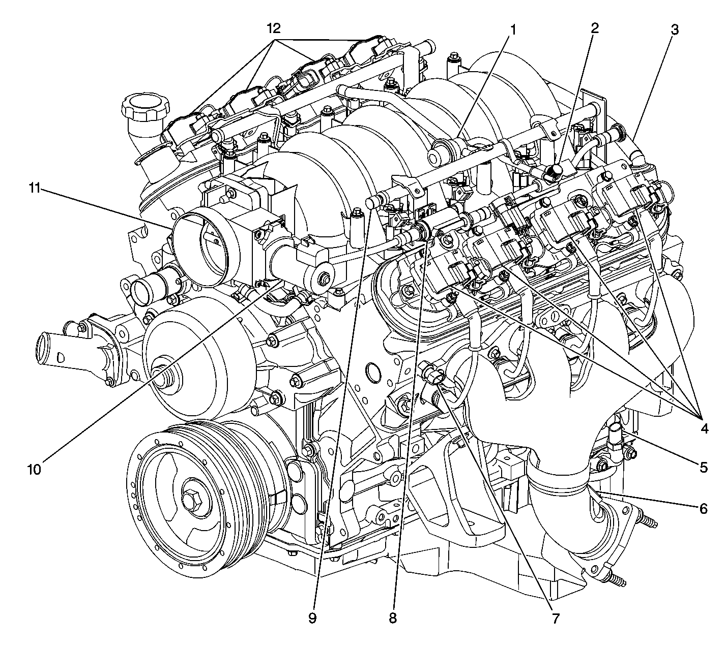
| Figure 1: |
Full Engine View Left Side
|
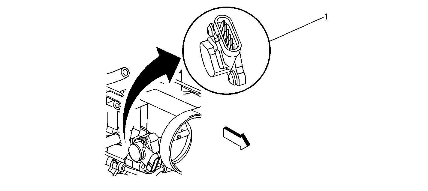
| Figure 2: |
Throttle Position Sensor
|
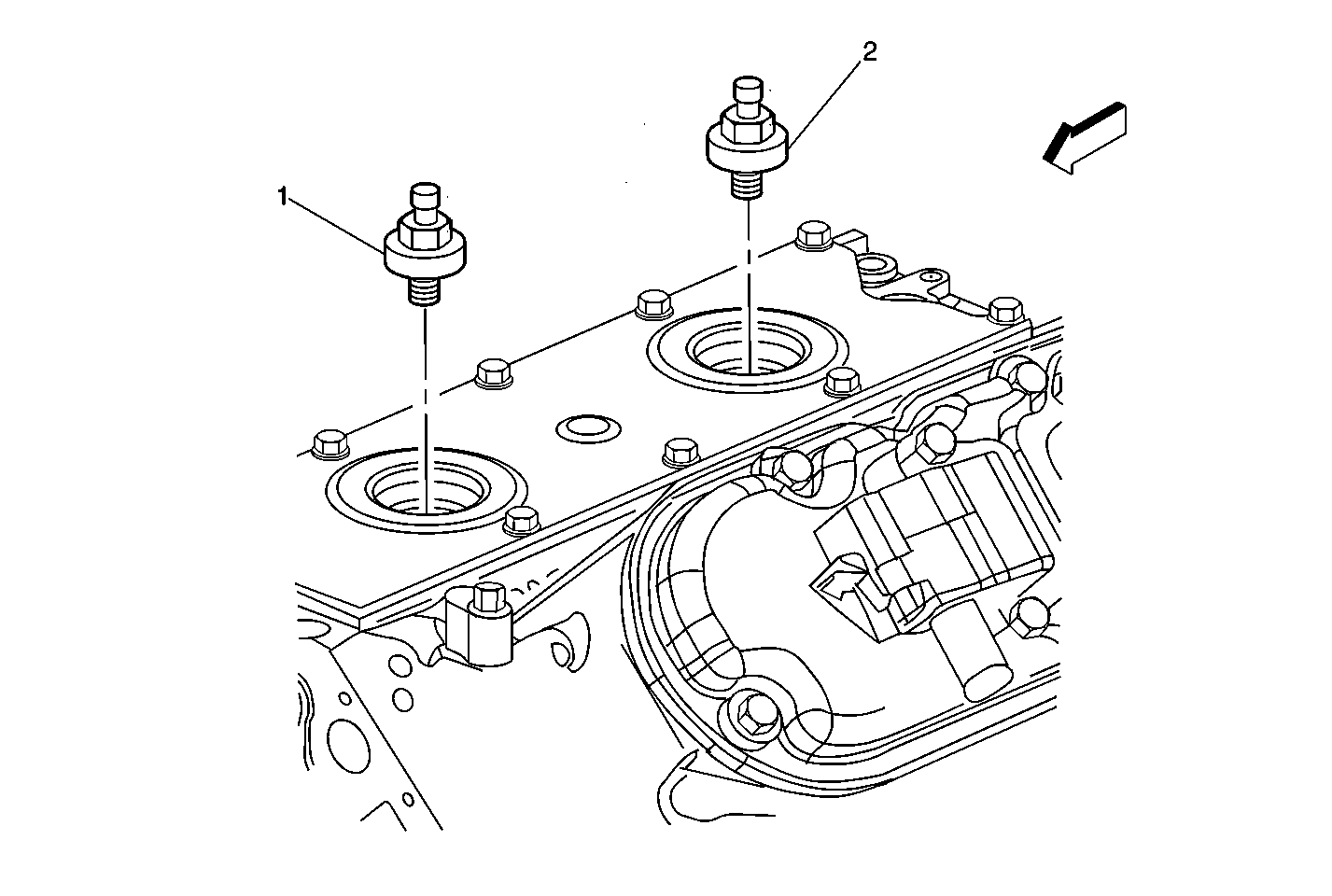
| Figure 3: |
Knock Sensors
|
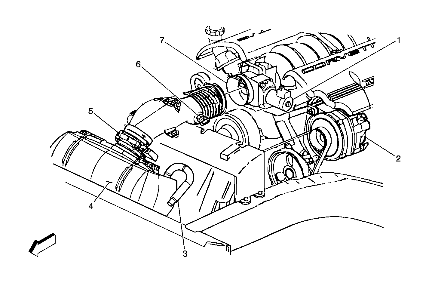
| Figure 4: |
MAF, IAT, TAC Motor, Generator, Throttle Body
|
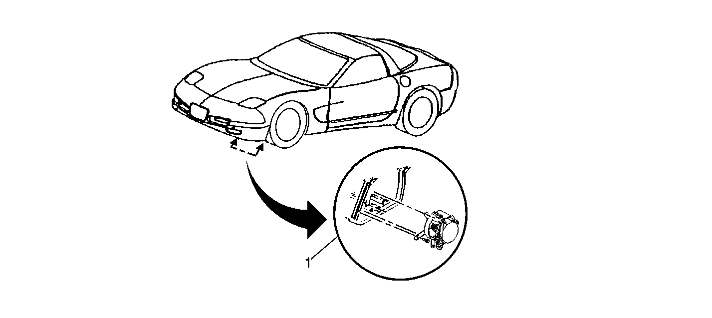
| Figure 5: |
AIR Pump
|
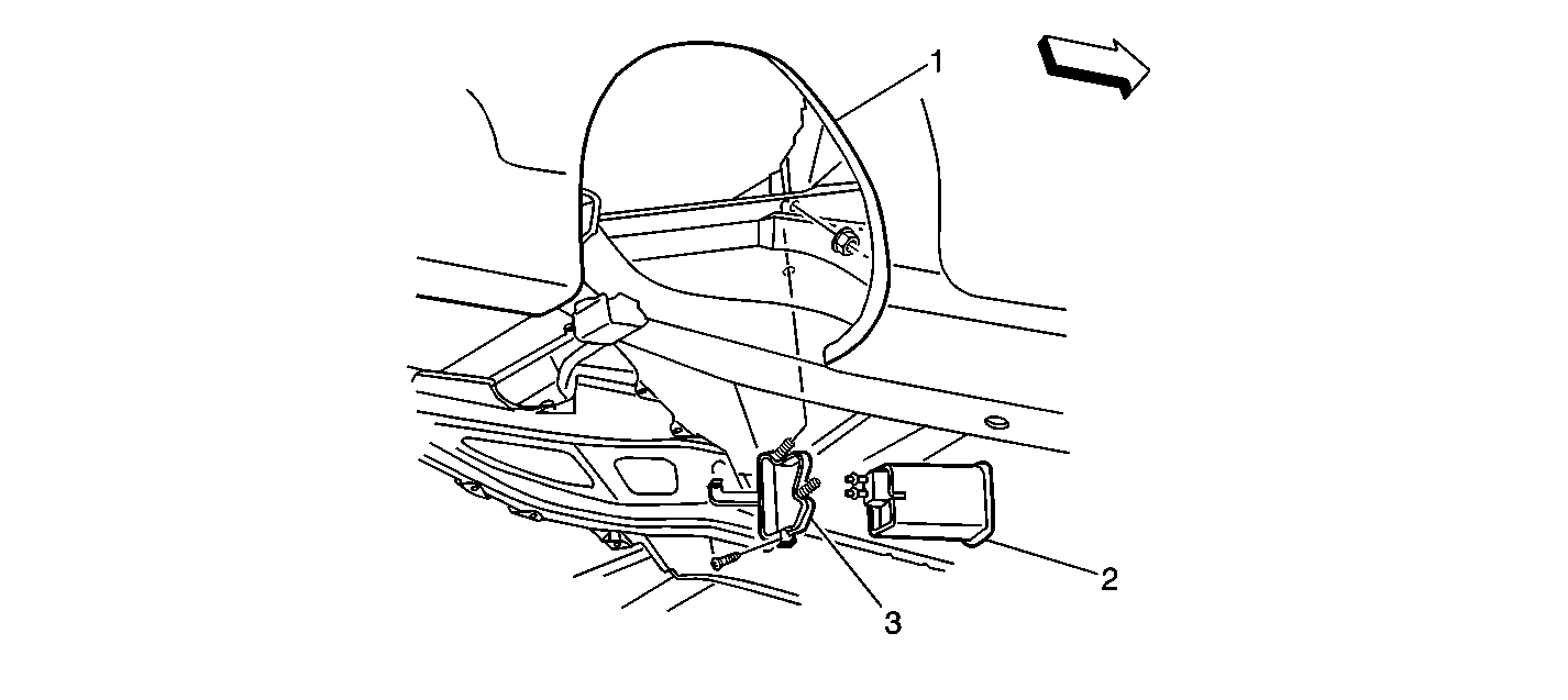
| Figure 6: |
EVAP Canister
|
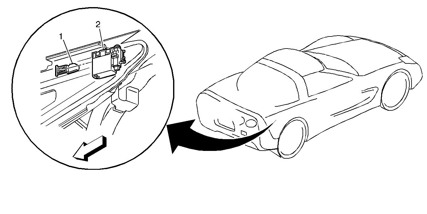
| Figure 7: |
EVAP Vent Valve
|
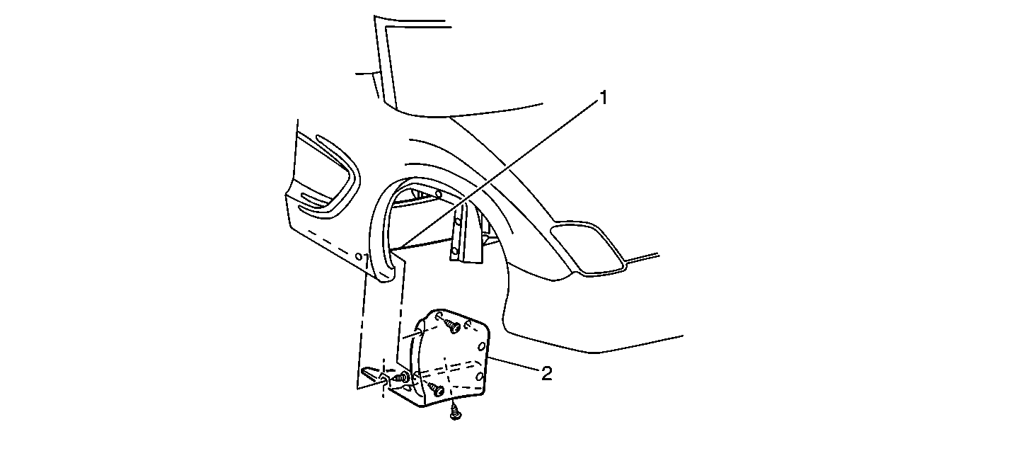
| Figure 8: |
PCM and TAC Module
|
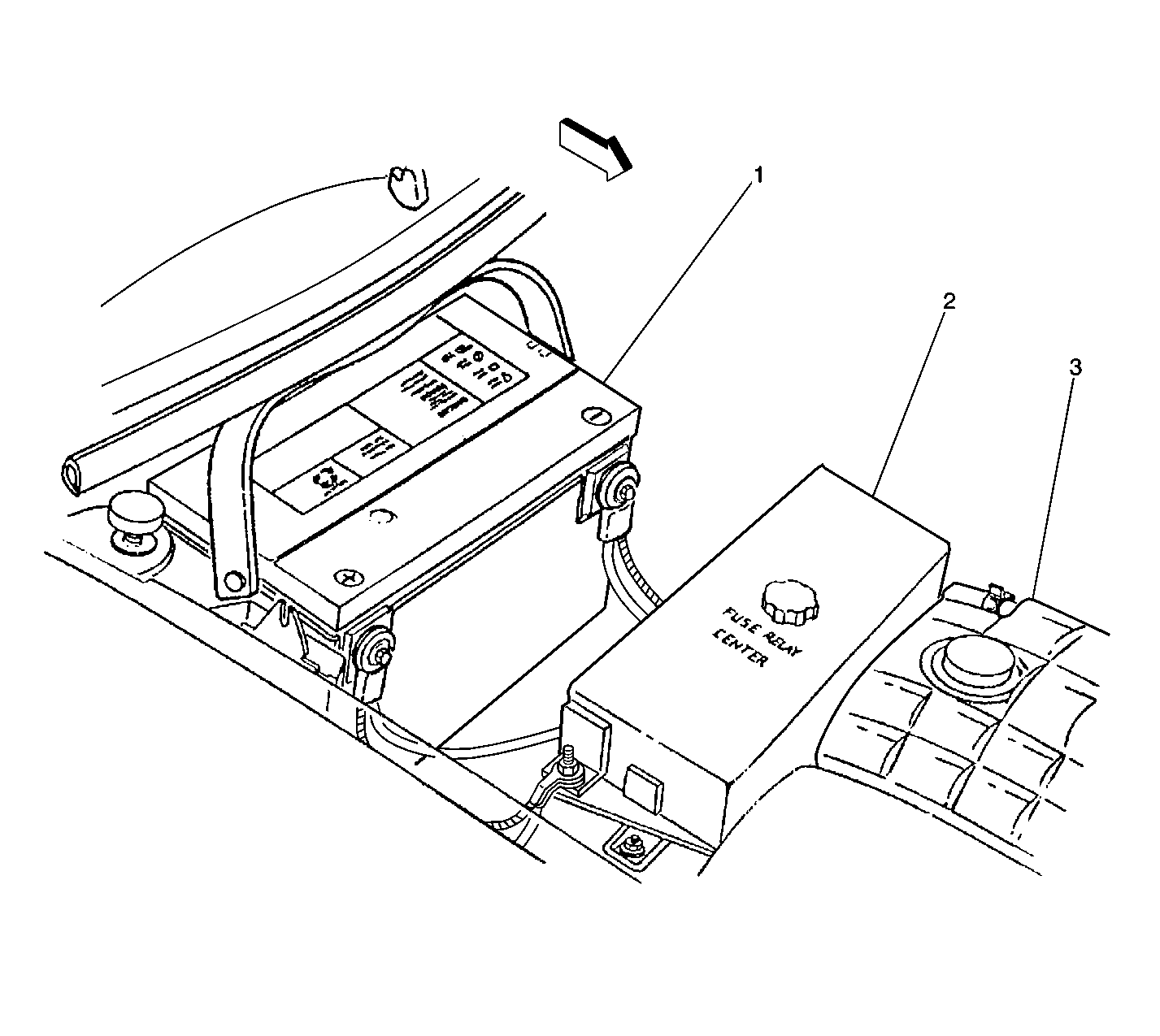
| Figure 9: |
Underhood Electrical Center
|
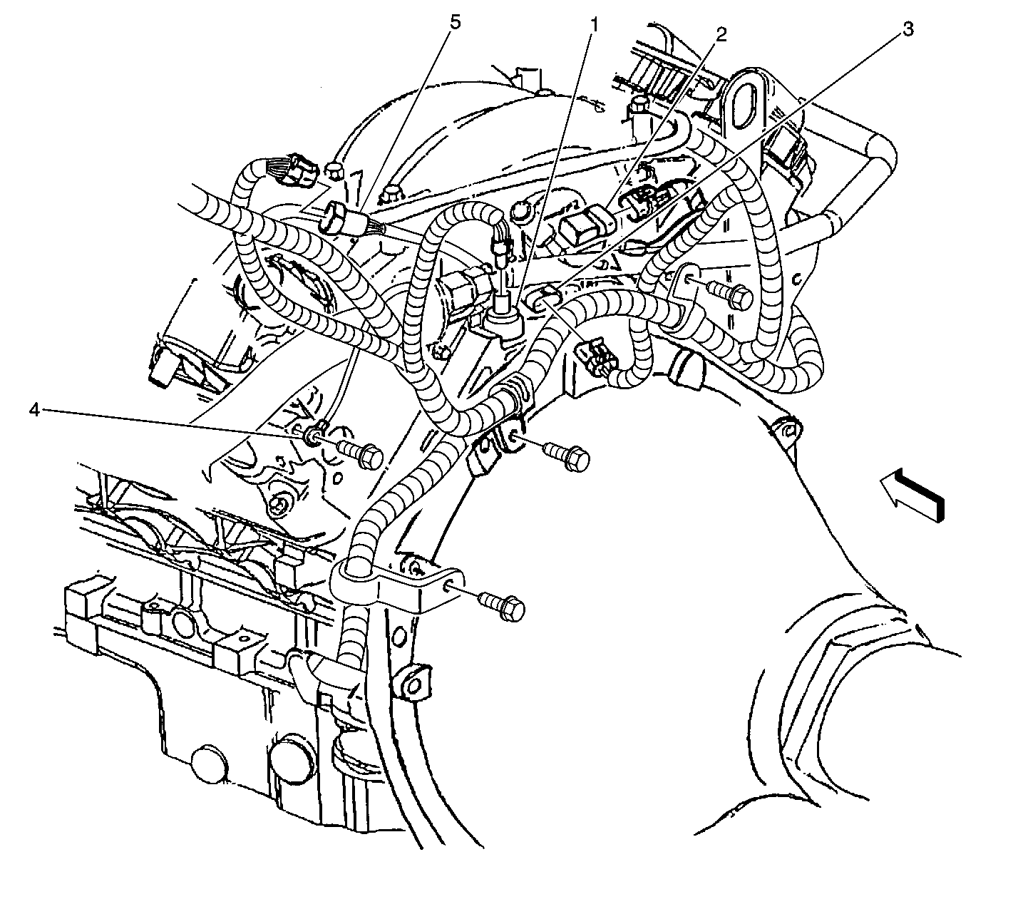
| Figure 10: |
EOP, MAP, CMP Sensors
|
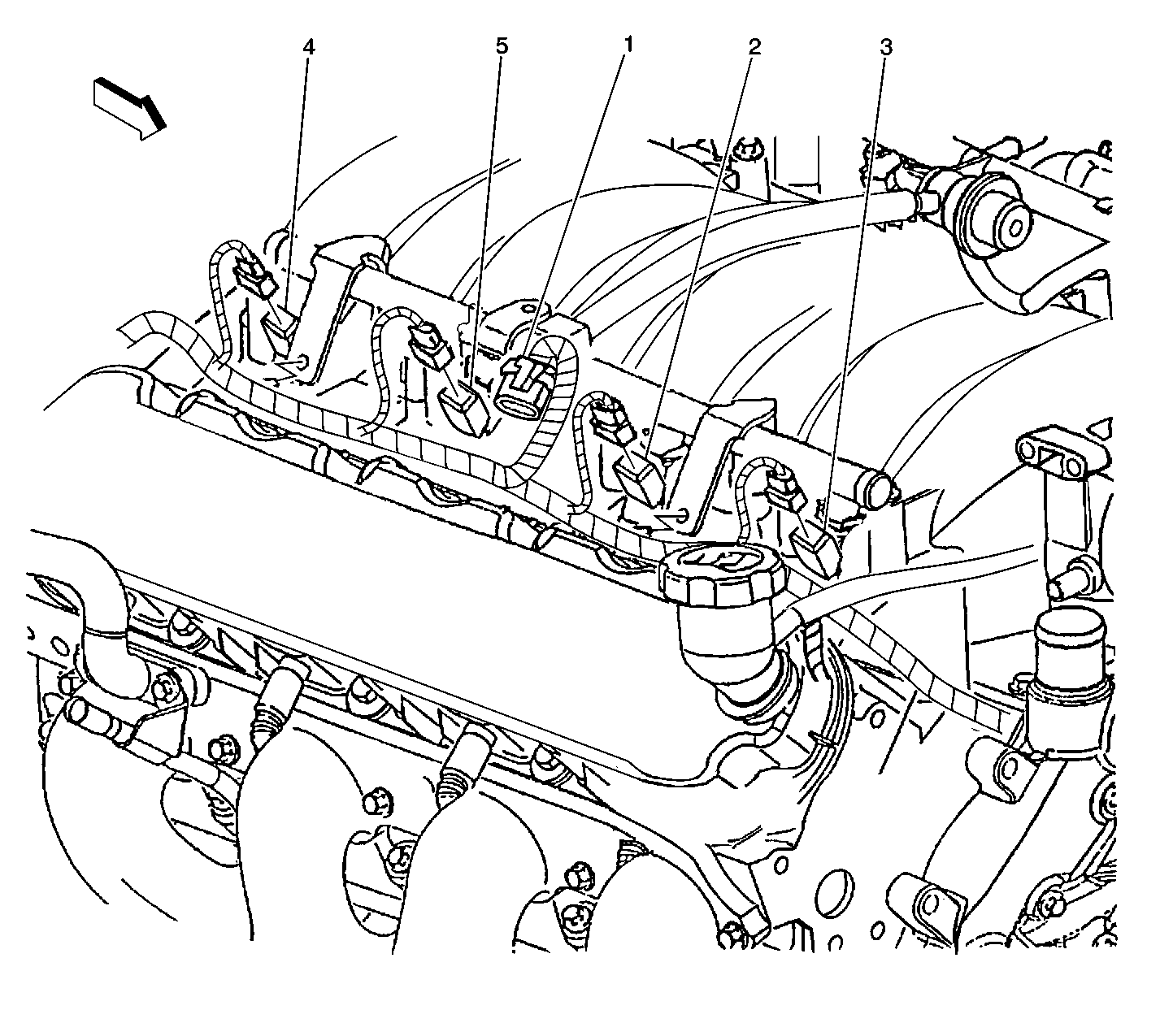
| Figure 11: |
Right Bank Fuel Injectors, C109 Connector
|
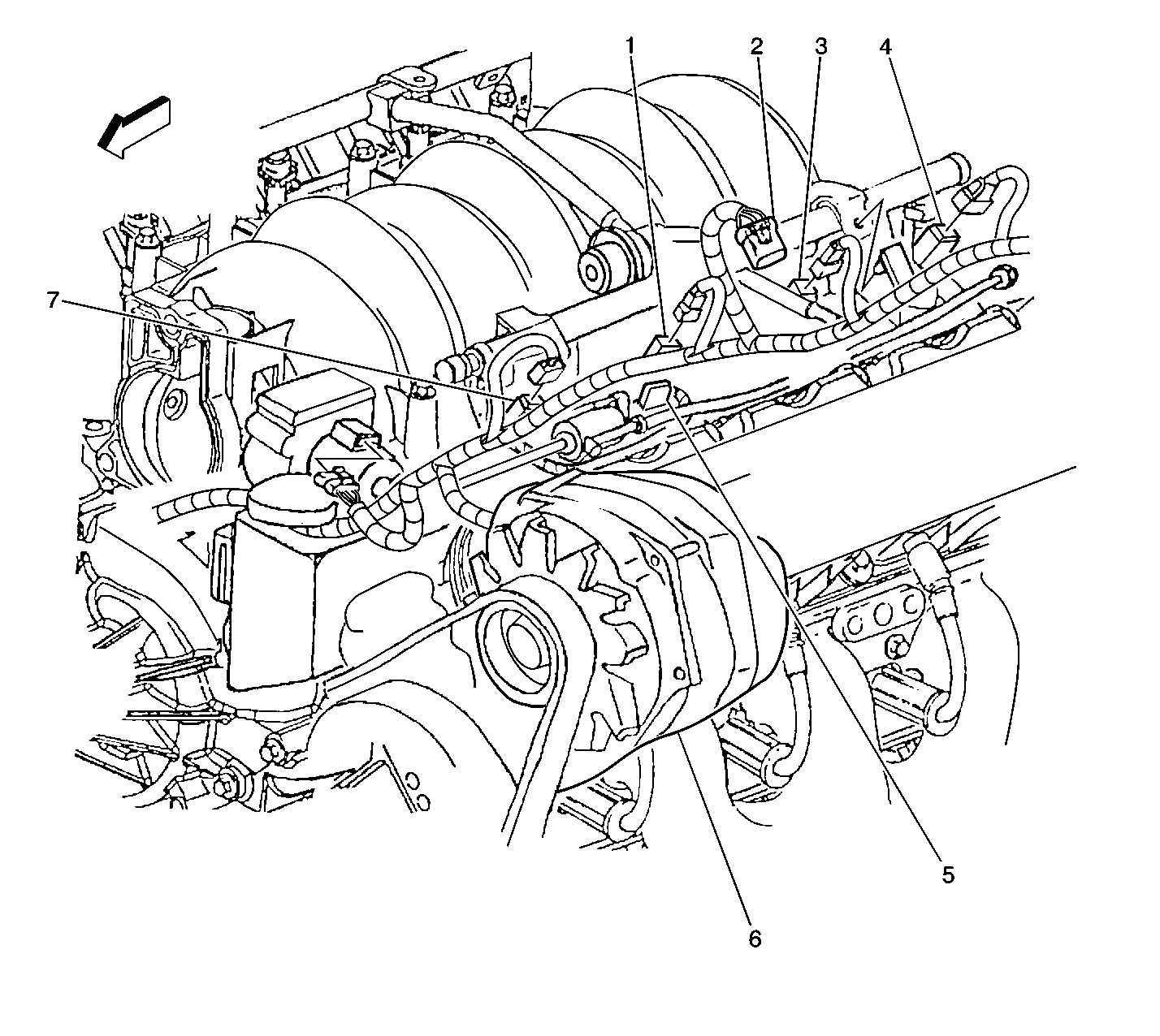
| Figure 12: |
Left Bank Fuel Injectors, Generator, C110 connector
|
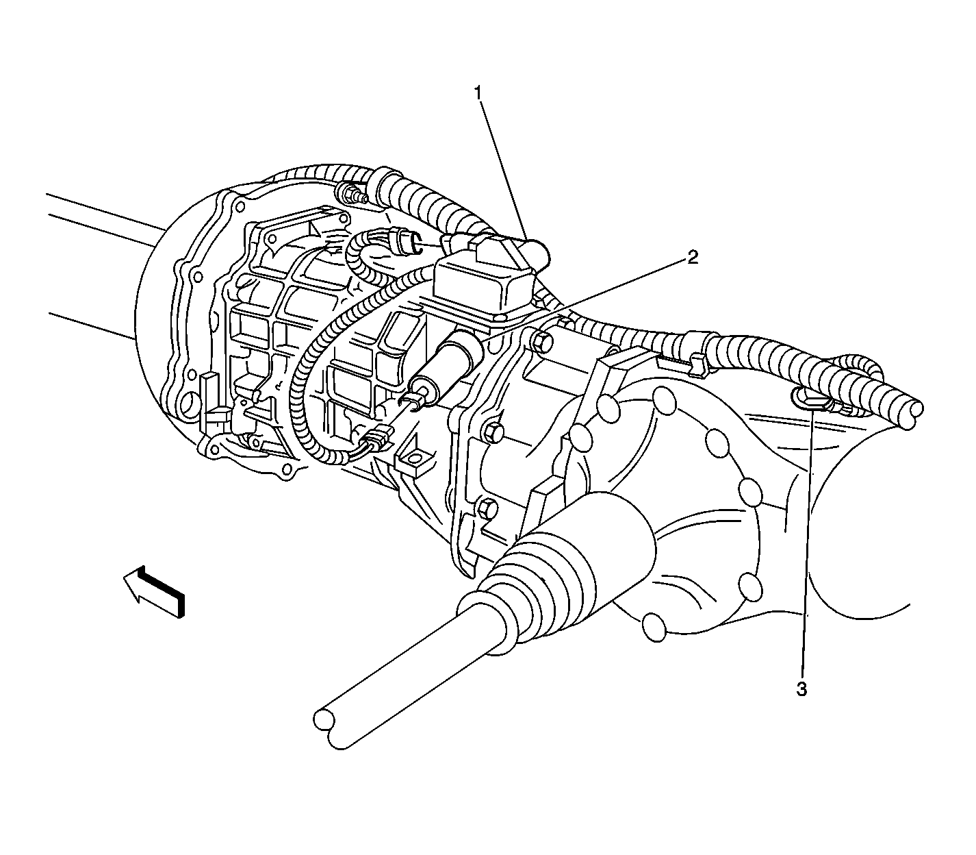
| Figure 13: |
LH side of the Manual Transmission
|
| Figure 14: |
LH side of the Automatic Transmission

|
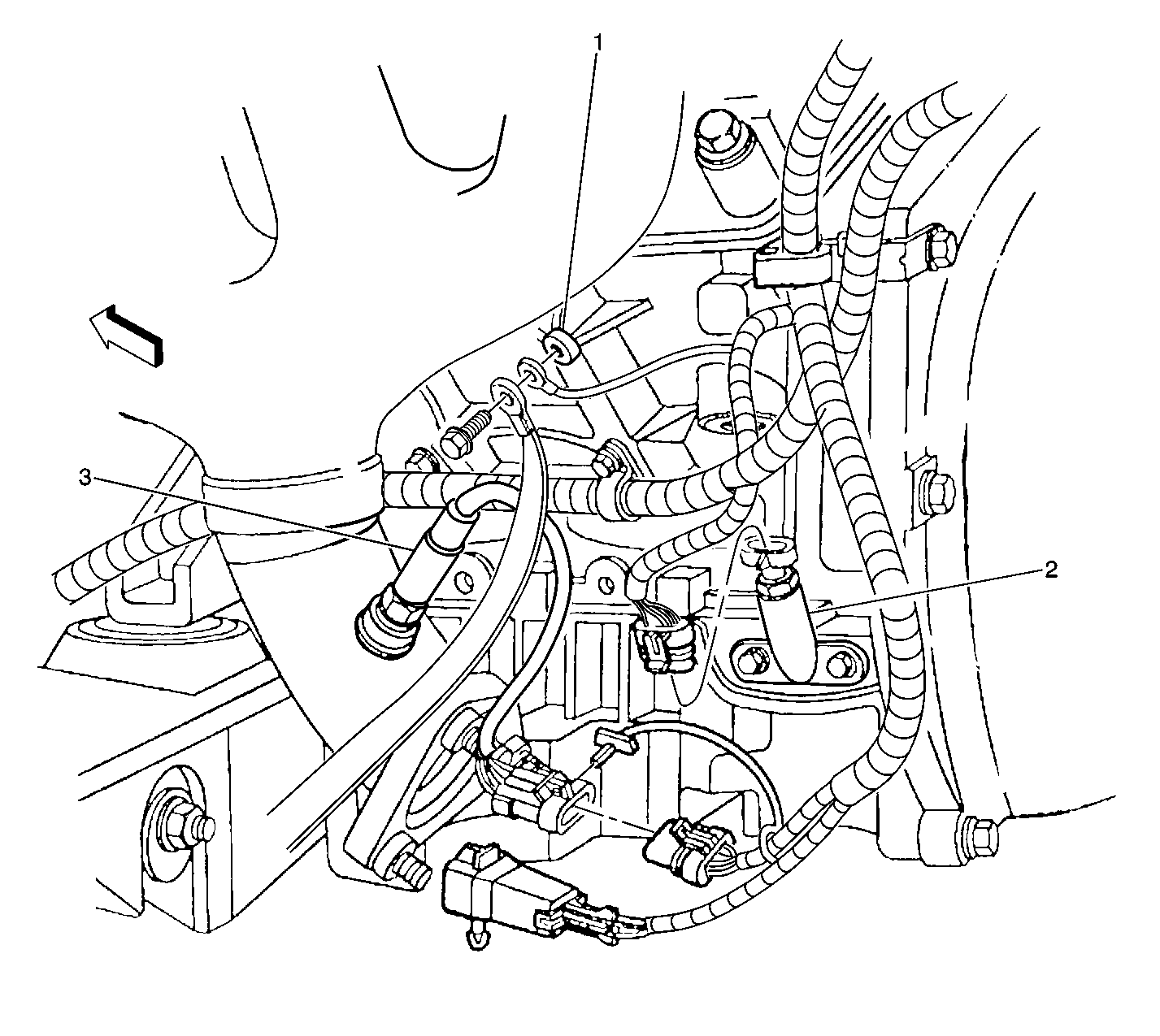
| Figure 15: |
Engine Oil Temperature (EOT) Sensor, Bank 1 Sensor 1 HO2S
|
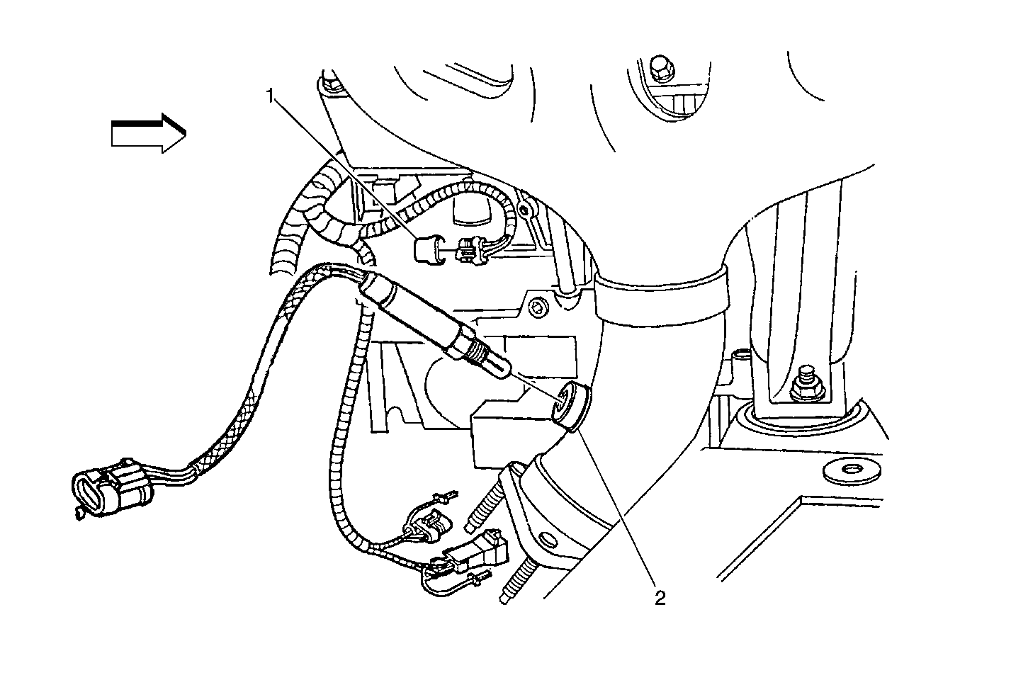
| Figure 16: |
CKP Sensor, Bank 2 Sensor 1 HO2S
|
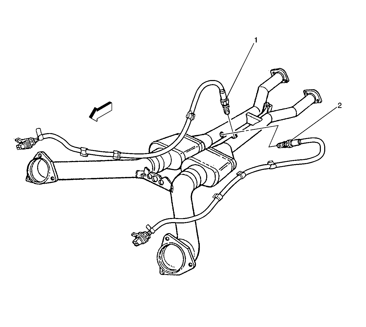
| Figure 17: |
Exhaust System, Bank 1 and 2 Sensor 2 HO2S
|


