Removal Procedure
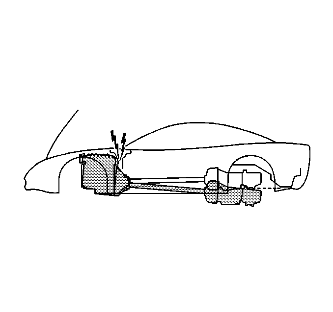
Notice: Failure to follow the proper removal and installation procedures may result in damage to the engine crankshaft thrust bearing.
Notice: When tilting down the rear of the driveline, observe the clearance between the rear of the engine and the composite dash panel. Do not allow the engine to rest unsupported against the composite dash panel, or vehicle damage may result.
Notice: When lowering and removing the rear of the driveline, observe the clearance between the rear of the transaxle assembly and the underbody to prevent damage.
Tools Required
J 42055 Transmission Support Fixture
- Disconnect the negative battery cable.
- Raise and suitably support the vehicle. Refer to Lifting and Jacking the Vehicle in General Information.
- Remove the exhaust system. Refer to Exhaust System Replacement in Engine Exhaust.
- Remove the driveline support assembly with the transaxle. Refer to Driveline Support Assembly Replacement in Propeller Shaft.
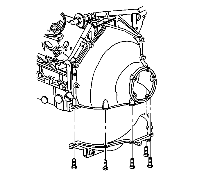
- Remove the engine flywheel inspection cover retaining bolts.
- Remove the engine flywheel inspection cover from the engine flywheel housing.
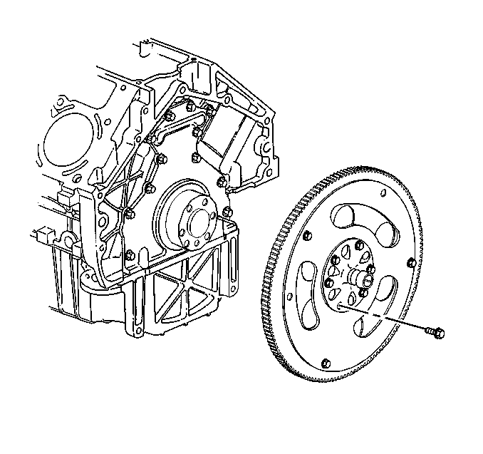
- Remove the engine flywheel. Refer to Engine Flywheel Removal and Engine Balancing .
Caution: Unless directed otherwise, the ignition and start switch must be in the OFF or LOCK position, and all electrical loads must be OFF before servicing any electrical component. Disconnect the negative battery cable to prevent an electrical spark should a tool or equipment come in contact with an exposed electrical terminal. Failure to follow these precautions may result in personal injury and/or damage to the vehicle or its components.
Installation Procedure
Tools Required
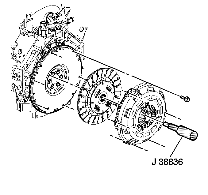
J 38836 Pilot Bushing Installer/Clutch Alignment Arbor
- Install the engine flywheel. Refer to Engine Flywheel Installation and Engine Balancing .
- Inspect the clutch pressure plate and the clutch driven plate for wear or damage. Replace as necessary.
- Adjust the clutch pressure plate, if necessary. Refer to Clutch Pressure Plate Adjustment .
- Install the clutch driven plate and clutch pressure plate to the engine flywheel.
- Install the visible clutch pressure plate bolts finger-tight.
- Rotate the engine flywheel.
- Repeat steps 5 and 6 until all the bolts are installed finger-tight.
- Using the J 38836 , align the clutch driven plate to the pilot bearing.
- Tighten the clutch pressure plate bolts.
- Install the engine flywheel inspection cover.
- Install the engine flywheel inspection cover retaining bolts.
- Install the driveline support assembly and the transaxle. Refer to Driveline Support Assembly Replacement in Propeller Shaft.
- Install the exhaust system. Refer to Exhaust System Replacement in Engine Exhaust.
- Lower the vehicle.
- Connect the negative battery cable.
- Program the Transmitters. Refer to Transmitter Programming/Synchronization in Keyless Entry.

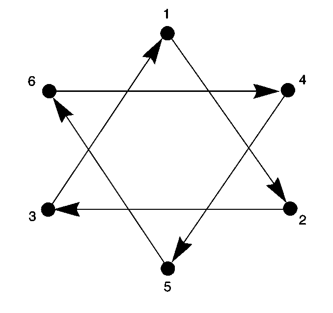
Notice: Use the correct fastener in the correct location. Replacement fasteners must be the correct part number for that application. Fasteners requiring replacement or fasteners requiring the use of thread locking compound or sealant are identified in the service procedure. Do not use paints, lubricants, or corrosion inhibitors on fasteners or fastener joint surfaces unless specified. These coatings affect fastener torque and joint clamping force and may damage the fastener. Use the correct tightening sequence and specifications when installing fasteners in order to avoid damage to parts and systems.
Tighten
Tighten the clutch pressure plate bolts in sequence and evenly over 4 increments with the fourth increment to 70 N·m (52 lb ft).

Tighten
Tighten the engine flywheel inspection cover retaining bolts to 25 N·m (18 lb ft).
Tighten
Tighten the negative battery cable bolt to 15 N·m (11 lb ft).
