Clutch Pressure Plate Adjustment Off-Vehicle
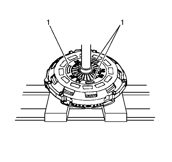
- Place the clutch pressure plate, flat surface down, on a press.
- Compress the pressure plate diaphragm spring fingers until tension is released from the stepped adjusting ring.
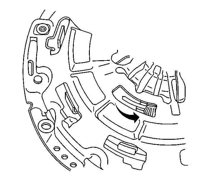
- Hold 2 screwdrivers or other suitable tools, and place them against 2 of the 3 stepped adjusting ring tension spring stops (1), just ahead of the adjusting ring tension springs.
- Using the screwdrivers, rotate the stepped adjusting ring counterclockwise (compressing the tension springs) until the adjusting ring steps are fully adjusted out, then continue to hold in position.
- Release the press pressure from the pressure plate diaphragm spring fingers.
- Release the adjusting ring tension spring stops.
- Remove the pressure plate from the press.


Clutch Pressure Plate Adjustment On-Vehicle
- Raise and suitably support the vehicle. Refer to Lifting and Jacking the Vehicle in General Information.
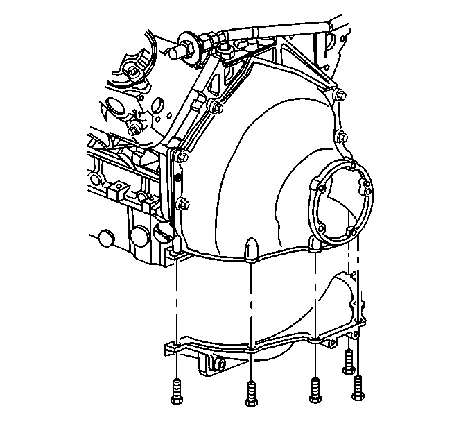
- Remove the engine flywheel inspection cover retaining bolts.
- Remove the engine flywheel inspection cover.
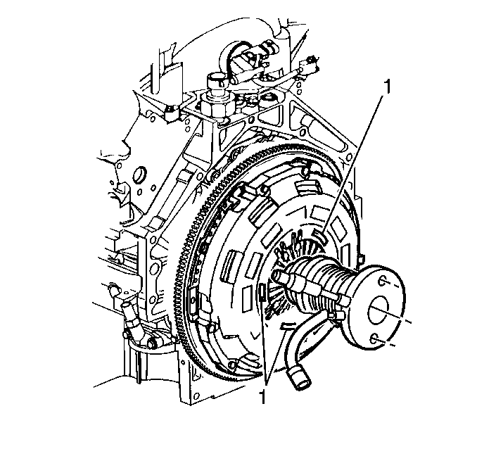
- Have an assistant press the clutch pedal until tension is released from the clutch pressure plate stepped adjusting ring, then continue to hold the pedal.
- Hold 2 screwdrivers or other suitable tools, and place them against 2 of the 3 stepped adjusting ring tension spring stops (1), just ahead of the adjusting ring tension springs.
- Using the screwdrivers, rotate the stepped adjusting ring counterclockwise (compressing the tension springs) until the adjusting ring steps are fully adjusted out, then continue to hold in position.
- Have your assistant release the clutch pedal.
- Release the adjusting ring tension spring stops.
- Install the engine flywheel inspection cover.
- Install the engine flywheel inspection cover retaining bolts.
- Lower the vehicle.

Important: The aid of an assistant will be necessary during this procedure.


Notice: Use the correct fastener in the correct location. Replacement fasteners must be the correct part number for that application. Fasteners requiring replacement or fasteners requiring the use of thread locking compound or sealant are identified in the service procedure. Do not use paints, lubricants, or corrosion inhibitors on fasteners or fastener joint surfaces unless specified. These coatings affect fastener torque and joint clamping force and may damage the fastener. Use the correct tightening sequence and specifications when installing fasteners in order to avoid damage to parts and systems.
Tighten
Tighten the engine flywheel inspection cover retaining bolts to 25 N·m
(18 lb ft).
