Pitman Arm Replacement Commercial
Removal Procedure
Tools Required
| • | J 24319-B Universal
Steering Linkage Puller |

- Raise and support the
vehicle. Refer to
Lifting and Jacking the Vehicle
in General Information.
- Remove the relay rod nut and the cotter pin from the pitman arm
ball stud.
Notice: Do not attempt to disconnect a steering linkage joint by driving a wedge
between the joint and the attached part. Seal damage may result which will
cause premature failure of the joint.
- Use the J 24319-B
in
order to remove the relay rod (3) from the pitman arm (5).
- Mark the pitman arm and the pitman shaft. This is to ensure that
you properly align the pitman arm and the shaft during assembly.
- Remove the pitman arm nut and washer.

Notice: Do not hammer on the pitman arm, pitman arm shaft or puller. Damage
to the pitman arm or steering gear may result.
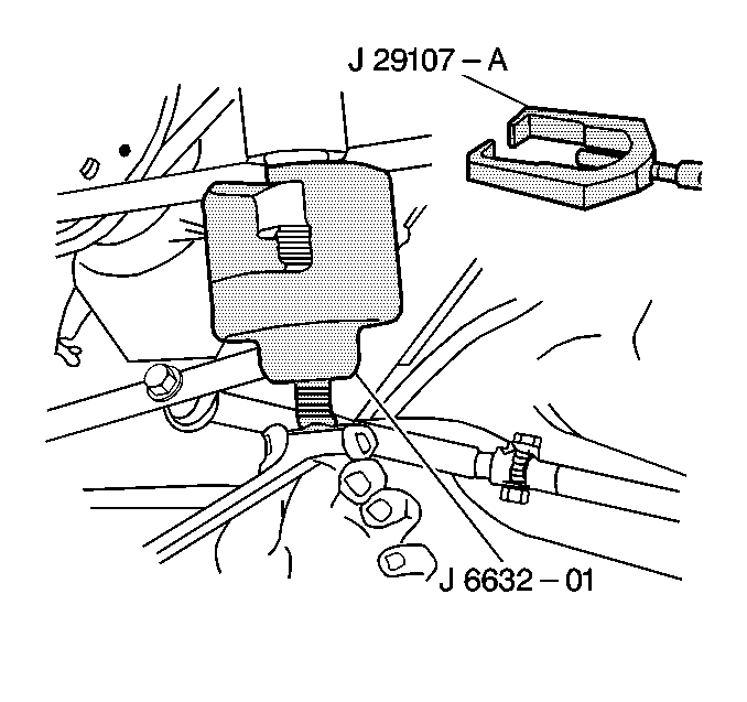
- Use the J 6632-01
or the J 29107-A
in order
to remove the pitman arm.
- Inspect the ball stud threads for damage.
- Inspect the ball stud seals for excessive wear.
- Clean the following components:
| • | The threads on the ball stud |
| • | The threads in the ball stud nut |
Installation Procedure
Tools Required
| • | J 29193 Steering
Linkage Installer (12 mm) |
| • | J 29194 Steering
Linkage Installer (14 mm) |

- Install the pitman
arm (5) on the pitman shaft.
Align the marks made during disassembly.
Notice: Use the correct fastener in the correct location. Replacement fasteners
must be the correct part number for that application. Fasteners requiring
replacement or fasteners requiring the use of thread locking compound or sealant
are identified in the service procedure. Do not use paints, lubricants, or
corrosion inhibitors on fasteners or fastener joint surfaces unless specified.
These coatings affect fastener torque and joint clamping force and may damage
the fastener. Use the correct tightening sequence and specifications when
installing fasteners in order to avoid damage to parts and systems.
- Install the pitman
arm washer and nut.
Tighten
Tighten the pitman arm nut to 250 N·m (184 lb ft).

- Install the relay rod
to the pitman arm ball stud.
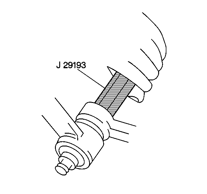
- Tighten the J 29193
or the J 29194
to 54 N·m (40 lb ft) in order to seat the tapers.
- Remove the J 29193
or the J 29194
.
- Remove the tool.

- Install the relay rod
nut and the cotter pin to the pitman arm ball stud.
Tighten
Tighten the pitman arm (5) to the relay rod (3) to 90 N·m
(66 lb ft).
- Lower the vehicle.
Pitman Arm Replacement Motorhome
Removal Procedure
Tools Required
| • | J 24319-B Universal
Steering Linkage Puller |

- Raise and support the
vehicle. Refer to
Lifting and Jacking the Vehicle
in General Information.
- Remove the relay rod nut or the connecting rod castellated nut
and the cotter pin from the pitman arm ball stud.
Notice: Do not attempt to disconnect a steering linkage joint by driving a wedge
between the joint and the attached part. Seal damage may result which will
cause premature failure of the joint.
- Use the J 24319-B
in
order to remove the relay rod (5) or the connecting rod (3) from the pitman
arm (JB8 configuration shown).
- Mark the pitman arm (4)and the pitman shaft. This is to ensure
that you properly align the pitman arm and the shaft during assembly.
- Remove the pitman arm nut and washer.
Notice: Do not hammer on the pitman arm, pitman arm shaft or puller. Damage
to the pitman arm or steering gear may result.

- Use the J 6632-01
or the J 29107-A
in order to remove the pitman arm.
- Inspect the ball stud threads for damage.
- Inspect the ball stud seals for excessive wear.
- Clean the following components:
| • | The threads on the ball stud |
| • | The threads in the ball stud nut |
Installation Procedure
Tools Required
| • | J 29193 Steering
Linkage Installer (12 mm) |
| • | J 29194 Steering
Linkage Installer (14 mm) |

- Install the pitman arm
(4) on the pitman shaft.
Align the marks made during disassembly.
Important: If a clamp-type pitman arm is used, spread the pitman arm just enough
with a wedge to slip the arm onto the pitman shaft. Do not spread the pitman
arm more than required to slip over the pitman shaft with hand pressure.
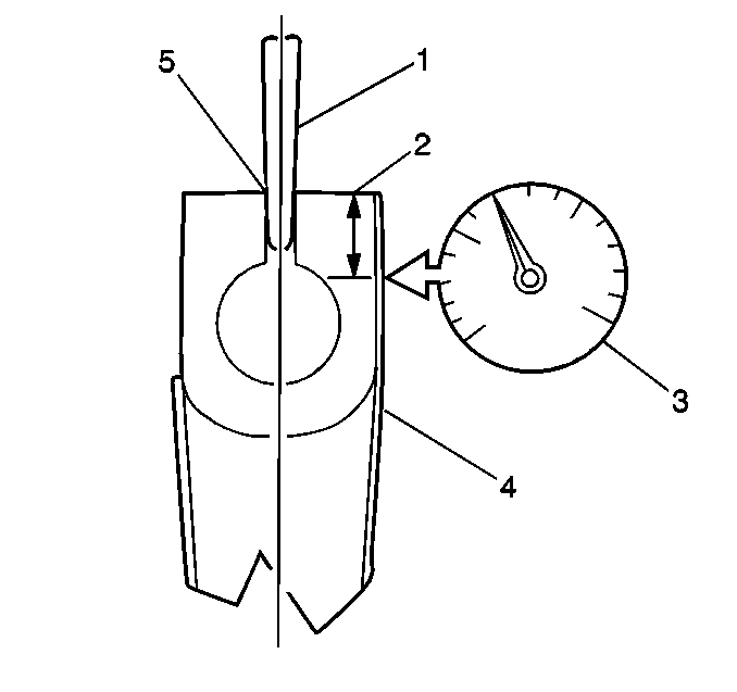
- Use the wedge tool (1) in order to spread the pitman arm (4) at a gap
(5) of 7.1 mm (0.28 in) when using a replacement clamp type
pitman arm. Maximum expansion with the wedge tool in place should read
0.10 mm (0.004 in) on the dial indicator (3). Distance
(2) is 30.2 mm (1.19 in).
Notice: Use the correct fastener in the correct location. Replacement fasteners
must be the correct part number for that application. Fasteners requiring
replacement or fasteners requiring the use of thread locking compound or sealant
are identified in the service procedure. Do not use paints, lubricants, or
corrosion inhibitors on fasteners or fastener joint surfaces unless specified.
These coatings affect fastener torque and joint clamping force and may damage
the fastener. Use the correct tightening sequence and specifications when
installing fasteners in order to avoid damage to parts and systems.
- Install the pitman
arm washer and nut.
Tighten
| • | Tighten the pitman arm nut with washer for JB8 applications to
170 N·m (125 lb ft). |
| • | Tighten the clamp-type pitman arm nut with washer for JF9 applications
to 135 N·m (100 lb ft). |

- Install the relay rod
or the connecting rod to the pitman arm ball stud.
- Tighten the J 29193
or the J 29194
to 54 N·m (40 lb ft) in order to seat the tapers.
- Remove the J 29193
or the J 29194
.
- Remove the tool.

- Install the relay rod
nut or the connecting rod castellated nut and the cotter pin to the pitman
arm ball stud. Refer to
Fastener Tightening Specifications
.
Tighten
Tighten the pitman arm (4) to the relay rod (5) to 159 N·m
(117 lb ft) for JB8 and JF9 applications (JB8 shown).
- Lower the vehicle.
Pitman Arm Replacement Commercial (I-Beam Front Axle)
Removal Procedure
Tools Required
| • | J 24319-B Universal
Steering Linkage Puller |

- Raise and support the
vehicle. Refer to
Lifting and Jacking the Vehicle
in General Information.
- Remove the connecting rod castellated nut and the cotter pin from
the pitman arm ball stud.
Notice: Do not attempt to disconnect a steering linkage joint by driving a wedge
between the joint and the attached part. Seal damage may result which will
cause premature failure of the joint.
- Use the J 24319-B
in
order to remove the connecting rod (7) from the pitman arm (8).
- Mark the pitman arm and the pitman shaft. This is to ensure that
you properly align the pitman arm and the shaft during assembly.
- Remove the pitman arm nut and washer.

Notice: Do not hammer on the pitman arm, pitman arm shaft or puller. Damage
to the pitman arm or steering gear may result.
- Use the J 6632-01
or the J 29107-A
in order
to remove the pitman arm.
- Inspect the ball stud threads for damage.
- Inspect the ball stud seals for excessive wear.
- Clean the following components:
| • | The threads on the ball stud |
| • | The threads in the ball stud nut |
Installation Procedure
Tools Required
| • | J 29193 Steering
Linkage Installer (12 mm) |
| • | J 29194 Steering
Linkage Installer (14 mm) |

- Install the pitman
arm (8) on the pitman shaft.
Align the marks made during disassembly.
Notice: Use the correct fastener in the correct location. Replacement fasteners
must be the correct part number for that application. Fasteners requiring
replacement or fasteners requiring the use of thread locking compound or sealant
are identified in the service procedure. Do not use paints, lubricants, or
corrosion inhibitors on fasteners or fastener joint surfaces unless specified.
These coatings affect fastener torque and joint clamping force and may damage
the fastener. Use the correct tightening sequence and specifications when
installing fasteners in order to avoid damage to parts and systems.
- Install the pitman
arm washer and nut.
Tighten
Tighten the pitman arm nut to 255 N·m (188 lb ft).

- Install the connecting
rod to the pitman arm ball stud.
- Tighten the J 29193
or the J 29194
to 54 N·m (40 lb ft) in order to seat the tapers.
- Remove the J 29193
or the J 29194
.
- Remove the tool.

- Install the connecting
rod castellated nut and the cotter pin to the pitman arm ball stud.
Tighten
Tighten the connecting rod (7) to the pitman arm (8) to 159 N·m
(117 lb ft). Refer to
Fastener Tightening Specifications
.
- Lower the vehicle.


