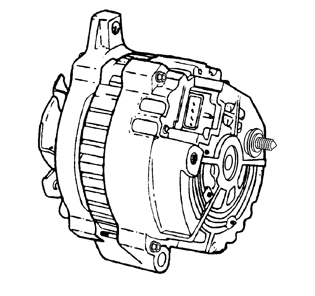
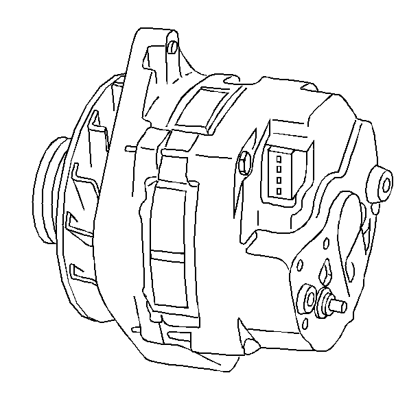
The charging system consists of the following components:
| • | The battery or batteries |
| • | The generator |
| • | The voltmeter |
The generator supplies the electrical power for charging the battery or batteries (diesel vehicles) and for operating the accessories.
CS-Series Generators

CS-Series generators feature a high ampere output per pound of weight. The CS stands for charging systems. The 130 or 144 is the measurement, in millimeters, of the outside diameter of the stator laminations.

The CS-144 generator is a larger version of the CS-130. Unlike the CS-130, the CS-144 is serviceable.

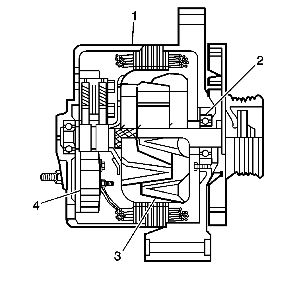
The CS-144 generator, with an internal regulator, does not have a diode trio. The delta stator (1), the rectifier bridge (4), and the rotor with slip rings and brushes (3), are electrically similar to other CS Series generators.
The generator uses a conventional fan and pulley. An internal fan cools the slip rings, the end frame, the rectifier bridge, and the regulator.
The voltmeter indicates the battery's state of charge in DC volts when the ignition switch is in the RUN position and the engine is not running. When the engine is running, the voltmeter indicates the condition of the charging system. Indications between the low and high warning zones represent the normal operating range. Readings in the low warning zone may occur when a large number of electrical accessories are operating in the vehicle and the engine is left at an idle for an extended period. This condition is normal since the charging system is not able to provide full power at engine idle. As engine speeds are increased, this condition should correct itself as higher engine speeds allow the charging system to create maximum power. Continuous readings in either warning zone indicate problems if any of the following conditions occur:
| • | Any abnormal charging condition |
| • | System voltage is too high or too low |

The regulator limits system voltage by controlling the rotor field current. When the field current is on, the regulator switches the rotor field on and off at a fixed rate of about 400 cycles per second. By varying the overall on/off time, correct average field current for proper system voltage control is maintained. At high speeds, the on time may be 10 percent and the off time may be 90 percent. At low speeds, and with high electrical loads, the on/off time may be 90 percent and 10 percent respectively.
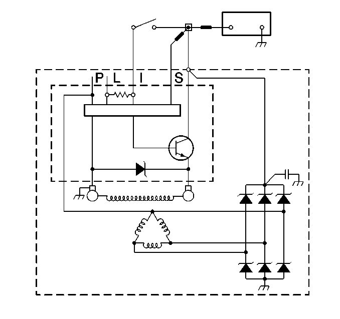
The regulator has four terminals--On CS-144 generators the terminals are P, L, I, and S. P, L, I, and S is stamped on the regulator. On CS-130 generators, the corresponding terminals are A, B, C, and D.
Generally, in CS generators the I or L terminal, or both, turns on the regulator and allows field current flow when the switch is closed. The L terminal must connect through an indicator lamp or a suitable resistor. The I terminal connects to B+ or through a resistor. These two terminals are often used in parallel and connected to two different vehicle circuits. Only the I terminal is used to turn on the regulator.
The P terminal (if used) connects internally to the stator and may be wired to a tachometer or other device. The S terminal may be used to "sense" voltage at another location on the vehicle for voltage control. If the S terminal is not used, the generator will use an integrated circuit in the regulator to "sense" voltage.
P model vehicles use a voltmeter in place of an indicator lamp. For schematics of the specific generator circuits, refer to Starting and Charging Schematics .
The CS-144 generator requires no periodic maintenance or adjustment. The CS-130 generator must be replaced if it is defective. Do not disassemble the CS-130 generator.
For bench repair of the CS-144 generator, refer to Generator Overhaul .
